AIRTRONIC / AIRTRONIC M. Manual - part 5
 

  Index      Engines     Eberspacher AIRTRONIC / AIRTRONIC M - service manual


Search            


Content   ..  3  4  5  6   ..


AIRTRONIC / AIRTRONIC M. Manual - part 5


17

Installation

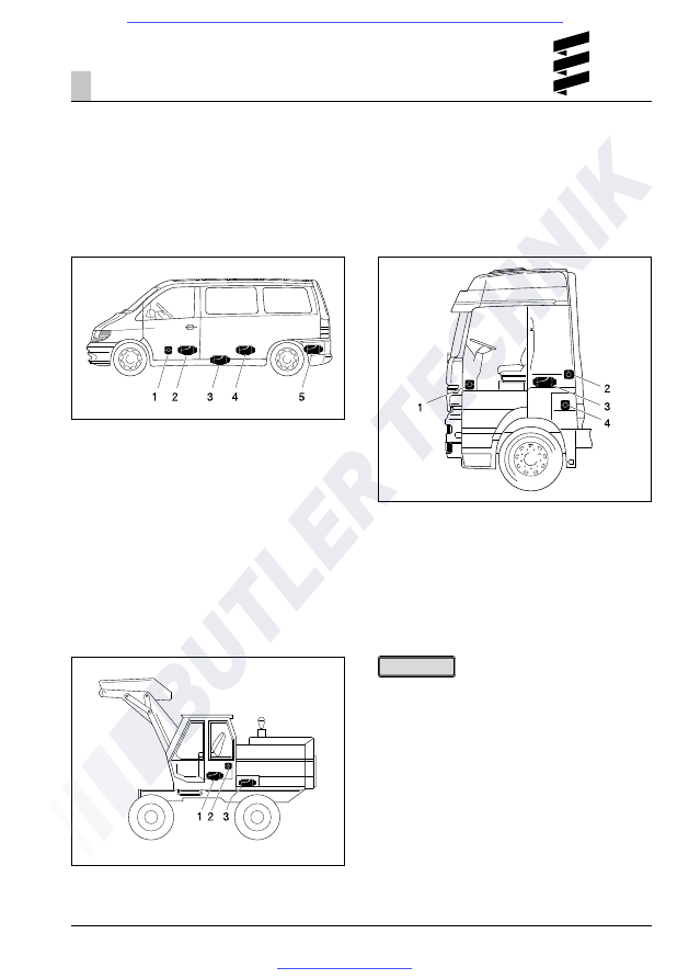
Installation in a car or people carrier

In a car or people carrier, the heater is preferably
installed in the passenger compartment or boot.
If it is not possible to install the heater in the
passenger compartment or boot, the heater can also
be mounted, protected against splashing water,
under the vehicle floor.

1

Heater in front of the passenger seat

2

Heater between the driver’s seat and the
passenger seat

3

Heater under the vehicle floor

4

Heater under the back seat

5

Heater in the boot

Installation in a truck (only diesel heaters)

In a truck, the heater is preferably installed inside the
driver’s cab. If it is not possible to install the heater
inside the driver’s cab, it can also be mounted in the
tool box or in a storage box.

Installation in an excavator cab (only diesel heaters)

In an excavator, the heater is preferably installed in
the cab. If it is not possible to install the heater in the
cab, the heater can also be installed in a storage box
outside the cab.

1

Heater in the passenger’s foot room

2

Heater on the cab rear wall

3

Heater under the bed

4

Heater in the tool box

1

Heater in the seat box

2

Heater on the cab rear wall

3

Heater in a protective case

• The installation suggestions made in the

installation instructions are just examples. Other
installation locations are possible, as long as they
correspond to the installation requirements stated
in these instructions.

• Other installation information (e.g. for boats and

ships) is available from the manufacturer on
request.

• Observe the tolerable installation position together

with the operating and storage temperatures.

Installation

Please note!

3

3

18

Possible installation positions

The heater is preferably installed in the normal
position as shown in the drawing.
Depending on the installation conditions, the heater
can be tilted by max. 30° (flow direction to the bottom)
or turned by max. 90° around its own longitudinal axis
(exhaust connection horizontal, glow plug points
upwards!).

Normal position horizontal (exhaust connection
downwards) with tolerable swivel range

Cable harness connection, right or left

If necessary, the cable harness connection can be
changed over to the other side of the heater. To do
so, the controller has to be removed and the lower
semi-circular cable harness cover unclipped.
The cable harness can then be rerouted in the
controller.
Then mount the controller again, position the jacket
shell and insert the cable harness bush and the bungs
in the corresponding recesses in the lower jacket
shell.

1

Heater air intake opening (fan wheel)

2

Position of the glow plug

3

Direction of flow

In the heating mode, the heater can deviate from the
shown normal or maximum installation positions by up
to +15° in all directions because of a slanting position
of the vehicle or boat, without any impaired functions.

Installation

3

19

1

There must be sufficient clearance between the
heater and the vehicle floor – also check that
the fan wheel runs freely.

2

The mounting surface must be flat and smooth.

3

The flange seal must be mounted.

4

The vehicle wall must be flat and smooth.

5

Reinforcement plate (if required, see above)

6

Spring washer

7

Hexagon nut M6 (torque 5

+1 Nm

)

Mounting and fastening

Make the necessary breakthroughs for exhaust,
combustion air and fuel as shown in the hole
diagram. The support surface for the heater foot
must be flat. An appropriate tool can be purchased
from the manufacturer for drilling the breakthroughs
and also smoothing the support surface.
The hole Ø 10.5 mm for the cable harness “dosing
pump” is not included in the picture drawing and must
be drilled after installation.

Picture hole

Special tool

If the sheet metal of the support surface is thinner
than 1.5 mm, an additional reinforcement plate will
have to be fitted.

Order no: reinforcement plate

20 1577 89 00 03

Order no: special tool

99 1201 46 53 29

Fastening the unit on the vehicle floor

Installation

3

Fastening the heater horizontally
to the vehicle wall

1

Contour of the bearing surface

20

Nameplate

The nameplate is fastened to the front of the heater.
The second nameplate (duplicate) is included in the
scope of supply of the heater.
If required, the duplicate nameplate can be adhered
in a clearly visible position on the heater or near to
the heater.

The regulations and safety instructions to be
observed for this chapter are stated on page 5.

1

Original nameplate

2

2

nd

 nameplate (duplicate)

Installation

3

Please note!


Content   ..  3  4  5  6   ..