AIRTRONIC / AIRTRONIC M. Manual - part 7
25
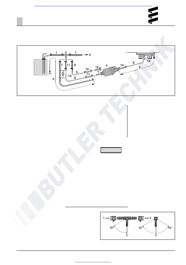
Fuel supply
Fuel feed point with T-piece from the fuel supply line
from the tank fitting to the vehicle engine
1
Fuel flow line, vehicle tank
2
To the vehicle's engine, mechanical fuel or
injection pump
3
T-piece, 8-6-8 or 10-6-10
4
Dosing pump
5
Fuel pipe, 4 x 1 (di = Ø 2 mm)
6
Fuel pipe, 6 x 2 (di = Ø 2 mm)
7
Fuel hose, 5 x 3 (di = Ø 5 mm)
8* Fuel pipe, 4 x 1.25 (di = Ø 1,5 mm)
9
Adapter Ø 6 / 4
10 Fuel hose, 3.5 x 3 (di = Ø 3.5 mm),
approx. 50 mm long
11 Fuel hose, 5 x 3 (di = Ø 5 mm),
approx. 50 mm long
12 Pipe connectors, da = Ø 4 mm
13 Fuel filter - required for contaminated fuel only.
* If necessary, a fuel pipe 4 x 1 (di = Ø 2 mm) can
be used for diesel heaters instead of the fuel pipe
4 x 1.25 (di = Ø 1.5 mm), Item (8).
The details regarding the pipe lengths remain
unchanged.
The fuel pipe, 4 x 1 must be order separately,
Order No. see spare parts list or additional parts
catalogue.
Installation
3
• Insert the T-piece (3) in the fuel flow line upstream of
the feed pump.
• Items (5), (9) and (12) are included in the "Plus"
installation kit only.
• Item (6) is included in the universal installation kit
only.
• Items (7) and (13) must be ordered separately. The
order no. is given in the additional parts catalogue.
Please note!
Installation position of the T-piece
Use the installation positions shown in the diagram
when inserting a T-piece.
1
Direction of flow from the fuel tank
2
Direction of flow to the vehicle engine
Possible pipe lengths
Intake side
Airtronic
a = max. 5 m
Airtronic M
a = max. 2 m
Pressure side
Diesel heaters
• For suction pipe di = Ø 2 mm,
b = max. 6 m
• For suction pipe di = Ø 5 mm,
b = max. 10 m
Petrol heater
• b = max. 4 m