Technology of watch production - part 84
 

  Index      Books     Technology of watch production (Tarasov) 1964 year


Search            


Content   ..  82  83  84  85   ..


Technology of watch production - part 84


In  polishing,  metal  is  removed more  quickly from  the  tip  of  the  tooth face 

than from  the base  of the tooth space ,   the  reason being that the tip of  the 
polishing- disk thread  blunts  rapidly.  In  orde r  to  avoid  distortion  of the 

tooth  shape,  the  allowance  for polishing is  only 2  to  3 

!l 

per  s ide and the  sur­

face  quality  required  after  milling is accordingly very  high  so that only mi­

croroughness  of  0.25  to  1 . 6  

It 

height need be  removed by polishing. 

Brazed with copper 

FIGURE  7.  Steady-rest of the S -5  machine 

The  allowance  for polishing is  usually fixed at  0 . 005  mm  per  side,  or 

0 . 0 1 - 0 . 02 mm on  a  diameter .   The polishing tim e  is a  function of the number 

of teeth,  the module and the  allowance,  and is  calculated using the  formula 

C•  M0,42  Z0.7  .0.5 . 

p = 

m ' 

• 

Os 

where 

em = 

a  parameter depending on the surface finish,  is taken between 

0 . 1 2  and  0 . 2 0; 

module,  mm; 

z  =  number of teeth; 

as 

allowance  for the tooth  thicknes s .  

The  polishing tim e  can  also be dete rmined  from  tables  o f  standards  (see 

Appendix  7 ).  Thus ,  for 

Cm = 

0 . 2 ,  

=  0 . 2 ,   and 

= 8,  o5 = 0 . 0 1 mm, 

T p = 

0 . 044 min. 

E xternal  diam eter,  thickness  and tooth p rofile  are  inspected after polish­

ing by the  same methods and using the  same  means  as were used for inspec­

tion after milling.  Surface  finish  is  inspected  visually using a  magnifying 

glass  (5X )  or  a  micros cope  ( 1 6X). 

• 

Orgmashpribor Institute standards,  1 954. 

3 3 3  

Polishing Journals  and  Shoulders 

The cylindrical surface and shoulder of journals  are polished simulta­

neously to  surface-finis h  class  1 2  o r  1 3  on the  S - 8a  machine  (Figure  8 ). 

FIGURE  8.  S-8a polishing  machine  for  polishing  journals and shoulders 

The  headstock ( 2 ),  the  steady- rest support  ( 3 ),  and  the  slide  (4 ),  with 

the  rocker arm  ( 5 ), are mounted on  the  bed  ( 1 )  (Figure  8 ,   a ) .   The  spindle 

with the p olishing wheel  (6 )  is  fastened  on the  right  end  of  the  rocker arm , 

while  its  left  end  carries  the  counterweight  ( 7 )  (Figure  8 ,  b ) .   The  slide 

can be  moved together with the  rocker arm  and  \1\,heel  in the  axial  and  radial 
directions  during machine  adjustment and  the  work headstock can  also be 

moved axially  during m achine  adjustment.  The headstock holds  the part 

against the  stationary  center  ( 8 )  (Figure  8,  a ) .   The  part is  rotated  by 

3 3 4  

pulley  ( 1 0 ),  through idlers  ( 1 1 ),  and  the  driver  ( 9 )  (Figure  8 ,   b ) .   Another 

driver is fixed to the  part.  When large pinions  are polished,  the  driver is 

set  directly  between  the  teeth.  A  special,  detachable  headstock  serves  for 

holding the parts  with  the  aid  of a  collet. 

The  rocker arm  can be inclined to a  maximum  angle  of  1 0°  in the hori­

zontal plane in  order to polish the  conical  surfaces of shafts .  The  work 

and  wheel  spindles are  driven by  the  electric  motor. 

A  stop  ( 1 2 )  restricts  the descent of the polishing disk. 

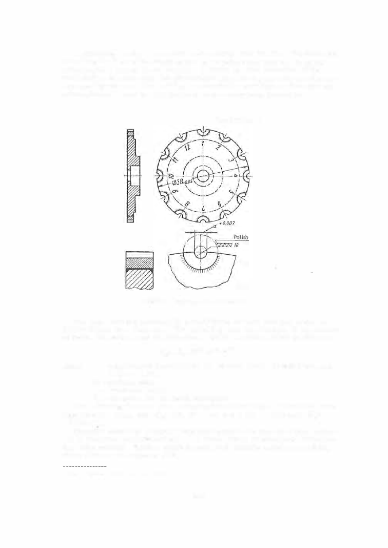
The steady - rest,  which supports  the journal  to be polished,  is  made of 

hard alloy and  is of a design similar to that of the  steady- rest us ed  for pol ­

ishing pinion  teeth  (see Figure  7 ).  When  one  bearing groove  wears ,  the 

s teady - rest is  rotated and  the  next bearing groove located under the  journal . 

The  numbe r  of bearing grooves  varies from  4  to  1 2 ,   depending on  the  di­

mensions  of the steady- rest and the bearings  themselve s .  

The bearings  grooves  are  cut and  finished by means o f  diamond  wheels 

or saws . 

Technical data,  S-8a machine 

Diameter of the journals to be polished.  mm  .  .  .  . 

• 

0.05-3 

Maximum journal length,  mm  . 

.  .  .  .  . 

.  . 

.  . 

• 

.  . 

Maximum length of the parts to be  machined ,  mm  .  . 

50 

Speed of polishing wheel,  rpm  .  .  .  .  .  .  .  .  .  .  .  .  .  .  .  860 or 1150 

Speed of driver washer,  rpm .  .  .  .  .  . 

• 

• 

.  .  .  .  .  .  . 

3500 

Polishing-wheel diameter,  mm  .  .  .  .  .  .  .  .  .  .  .  .  .  . 

36-75 

A ngle of rotation of the  carriage,  degrees  .  .  . 

.  • 

• 

1 0  

Electric motor  . 

.  • 

.  .  .  .  .  . 

.  . 

.  .  . 

.  .  .  . 

• 

.  .  .  . 

0.125 kw , 

1 .400 rpm 

Carbide  polishing  wheel s .  

Journals  and  shoulders  are  polished by a 

carbide  wheel,  lubricated in  operation  with  mineral oil . 

FIGURE  9.  Carbide  wheel 

FIGURE 10.  Contact between  rhe polishing 

wheel and the part 

The  carbide  wheel  consists  of a  base  washer  ( 1 )  and  a  carbide  ring  (2 ) 

(Figure  9 ),  which  is  either brazed to  the  washer  (Figure  9 ,   a )  or  screwed 

to it with  the  aid  of plate  ( 3 )  (Figure  9 ,  b ) .   The  amount of  carbide  required 

for such rings is  smaller than the  amount  required for a  solid wheel .  A 

3 3 5  

composite  wheel  is  also  easier to balance ,   which  is  ve ry  important  when 
small  journals  are polished ,   as  a  poorly  balanced  wheel  can  throw  the 

journal  out  of the  s teady- rest. 

In all  carbide  rings  the  cylindrical  working 

width A  is  larger than the  working-face  width,  since  the  shoulder is  usually 

seve ral  times  sho rter  than the  journal .  The shape and dimensions of carbide 
rings  are  given  in  Table  4 .   The  carbide  alloys  used are  VK6 ,   VK8  and 

VK l O,  all  characterized by high wear  resistanc e .  

TABLE  4 

Dimensions of carbide  polishing rings 

No. 

D, 

D, 

1 .5 

36 

34 

34 

34 

� 

51 

49 

49 

34 

3 .5 

65 

63 

57 

42 

1 1  

5.5 

2 .5 

2 .5 

75 

73 

67 

42 

11 

5 .5 

Small  groove s ,   inclined  at  1 0  to  2 0°  relative  to  the  wheel  axis  and  form ­

ing  teeth  of  more  or  less  regular  shape  are  traced on the  cylindrical  and 

face  ring surfaces .  These teeth  scrape  the machined  surface  during opera­

tion. 

The  grooves  on the  face  surface  are  finer than  those on the  cylindrical 

surface,  as  the  metal - removal  rate  for  the  shoulder is  considerably higher 

than that for  the  cylindrical  surface .  This  is  due  to  the  fact that the  cylin­

d rical  surface of the  ring  contacts  the cylindrical  surface of the journal 

along a  narrow area,  while  the  face  surface  of the  ring and  the  journal 

shoulder contact  along  the  hatched area  (Figure  1 0 ).  The  polishing allow­

ance for the  shoul der is not much larger than  that for the  cylindrical  surface 

and  therefore,  in orde r  to  finish the polishing of both surfaces at the  same 

time,  the face  teeth  are made by  a  finer  diamond powder  so that their  cutting 

capacity is  reduced. 

Wheels  having coarse,  medium ,  or fine  cut are used,  depending on the 

surface-finish  quality  required.  The  relationship  between  the  type  of cut 

and  the  surface -finish  quality is  given  in  Table  5 . 

The  part to  be  polished  is  fastened by  one  of  its  ends  in  the  S- 8a- machine 

headstock,  while  its  othe r  end is  supported on the  steady - rest (Figure  1 1  ) .  

The  polishing wheel is  placed o n  the  journal  before  the  machine  is  s tarted .  
The  wheel  and  the  work then begin t o  rotate;  eithe r  in  the  same  direction  or 

in opposite  directions .  The wheel revol ves  at  8 6 0  o r  1 1 50 rpm ,  giving a 

peripheral  speed  of  2 00  o r  2 7 0 m /min  for  a  7 5 mm  diameter  wheel .  

3 3 6  


Content   ..  82  83  84  85   ..