Technology of watch production - part 82
 

  Index      Books     Technology of watch production (Tarasov) 1964 year


Search            


Content   ..  80  81  82  83   ..


Technology of watch production - part 82


C h a p t e r   IX 

FINISHING  OPERA TIONS 

Finishing  operations  occupy  a  prominent  place  in  watch  production. 

'.ilfatch-movement parts  are  ground,  lapped and  polished in  order  to  reduce 
friction and increase their  resistance  to  corrosion .  External parts  (cases , 

dials  and  hands )  are  subjected  to  finishing operations  designed to  give  them 

an aesthetic appearance and  to  make  them  resistant to  light,  wear and  cor­
rosion.  The complex of finishing operations  includes  grinding,  lapping and 

polishing as  well  as  electroplating and  chemical  and  varnish  coating.  Steel 

parts  of the  watch  movement are  subjected to heat treatment  (hardening  and 

tempering) before being ground and polished .   Hardening and  tempering con­

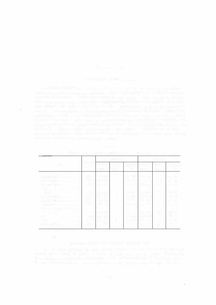
ditions  for typical  watch parts  are  given in Table  1 .   Parts  made of non­

ferrous alloys are  s ubjected to  additional  mechanical,  chemical  and  electro ­

chemical  proces sing before being coated .  

TABLE  1 

Hardening and tempering conditions for typical watch  parts 

Hardening 

Tempering 

Part 

Grade of 

hardness , 

time, 

hardness, 

steel 

temper-

time, 

temper-

ature, oC 

min 

HRc 

ature, 

oc 

min 

HRc 

Balance staff 

.

.

.

.

.

.

.


UlOA 

780- 790 

63- 65 

1 8 0-190 

12 

59-61 

Barrel arbor  . . . . . . . . . .  

UlOA 

780- 790 

63-65 

200-210 

12 

56-58 

Cannon pinion  . . . . . . . .  

UlOA 

780- 790 

63-65 

350-400 

1 0  

49-52 

W inding wheel and keyless 

wheel . . . . . . . . . . . . .  

UlOA 

780- 790 

63- 65 

200-210 

20 

56-58 

Escape wheel  . . . . . . . . .  

UlOA 

780-790 

63-65 

280-290 

1 0  

53-55 

Pallet lever . . . . . . . . . .  

UlOA 

780-790 

63- 65 

280-290 

53-55 

Regulator 

.

.

.

.

.

. .

.

.

.

UlOA 

780-790 

63- 65 

280-290 

1 0  

54-56 

Hour-setting and winding 

lever 

.

.

. . .

.

.

.

.

.

. .

U10A 

780- 790 

63-65 

200-220 

10 

56-58 

Pinions 

. . . . . . . . • . . . .  

U7AV  8 00-820 

62-64 

280-300 

52-55 

Screws 

.

.

.

.

.

.

.

.

.

.

.


U7AV 

800-820 

62-64 

330-340 

47-50 

Pallet arbor 

. . . . . • . . . .  

U7AV 

800-820 

62�64 

200-210 

1 0  

56-58 

GRINDING,  LAPPING  AND  POLISHING  OF  STEEL  PARTS 

The  working surfaces  of  steel  parts ,  such as  the  journals  of pinions  and 

staffs  (must have,  at least,  a  class  1 2  finish  in  order to  reduce  friction  in 

the  watch movement  to  a  minimum.  The  outer s urfaces  of the  parts  (the 

faces of s c rew heads,  the  upper  faces  of  the  keyless  and  escape  wheel s ,  

3 2 5  

the  regulators,  etc . )  must be  finished to  surface - quality  class  1 1 - 1 2  at 
least,  in o rder to  give  the  parts  an  aesthetic appearance  and  to  make  them 

corrosion-resistant . 

Grinding,  lapping and  polishing  of  the  parts  after  hardening and  temper­

ing gives  them  the  surface- finish  quality  required .  The first two are pre­

paratory  operations  which precede polishing and impart a  class  8  or  9 

surface-finish  quality. 

Pinions  and  staffs  turned  in  automatic machines  have  a  class  8  or 9  sur­

face-finish  quality and therefore  need no additional  stages prior to  polishing. 

Certain flat parts ,  such  as keyless  wheels,  hour- s etting and  winding 

levers ,  are  ground in o rder to  level  their faces  and  remove  burrs  resulting 
from blanking. 

Polishing  removes  microroughness  0 . 2 5  to  3.2 

!L 

high from machined sur­

fac e s .  

Polishing i s  classified as being dimensional  or  decorative .  Dimensional 

polishing has  the  dual aim  of  providing a  class 1 1  to  1 3  s urface finish and of 
bringing the dimensions  within the required tolerances ,  Decorative polish­

ing,  or buffing,  is applied to  impart an aesthetic  appearance  to the parts . 

Although no  dimensions  are  specified in  decorative  polishing,  the  thickness 

of the metal  layer removed must lie  within the tolerance limits  on the part 

dim ens ions . 

The  grinding,  lapping and  polishing methods used in  watch production 

are  extremely divers e  and  depend both on the  dimensions  and  shape  of the 

machined part and  on s urface - finish requirements .  The  abrasives  us ed are 

also  very  diverse. 

Lapping  and  polishing  flat  steel  parts . 

Flat parts are lapped and polished 

on the  S - 1 5  two- spindle  vertical machine  (Figure  1 ). 

The  machine  consists  of  a  base ,   inside  of  which an  electric  motor is 

mounted,  a  bed with a  round  table  and c ontrol  me chanism,  and a  support 

which  carries  two spindles .  The  electric motor drives  the  round  table  and 

the  machine  spindles  (Figure  2 )  through  gears  ( 1 - 2 - 3 - 4 - 1 0- 1 1 - 1 2 - 1 3 ) and 

( 1 - 2 - 3 - 4 - 5 - 6 - 7 - 8 - 9 )  respectively . 

The  gears  ( 1 1 )  and  ( 1 3 ),  fitted  freely  on  a  shaft,  transmit  rotation  to 

the  round  table  through  a  draw  key,  by means  of which two  speeds  of  rota­

tion  can  be  imparted to  the  machine  table . 

The  duration  of  operation  is  adjusted by means  of  a  special  device.  The 

gears  ( 1 4 )  and  ( 1 7 ),  which are part of  a  planetary  train,  are  mounted  on  the 

same shaft with  gear  ( 1 0 ).  The  planet  gears  ( 1 5 )  and  ( 1 6 )  are  rigidly inte r­

connected by  a bushing and  fitted on a  shaft fixed  to  gear  ( 1 0 ).  One  revolu­
tion  of  gear  ( 1 0 )  corresponds  to  0. 00037 revolutions of the shaft carrying 

the  spiral  gear  ( 1 8  ),  and  therefore  to  0. 00037 revolutions  of the  shaft  car­

rying the spiral  gear ( 1 9 ) .   If 

n  = 

9 0  rpm for gear ( 1 0),  gear ( 1 9 )  will  re­

volve  at  0 . 03 3  rpm  ( 1 / 3 0  rpm ),  as can be calculated using the  planetary­

transmission  formula  for  one  revolution  of  gear  ( 1 0 ) 

1 -. 

0,00037. 

The  shaft  which  carries  gear  ( 1 9 )  also  has  a  jaw  clutch  ( 2 0 ),  on whos e  

left  elem ent  the  pin  (2 1 )  i s  fastened.  When shaft and clutch  revolve,  the 

pin  (2 1 )  approaches  the  stop  (2 2 )  and lowers  it.  The  stop  (22 ) is  thus  made 

to act on a micros witch  which  stops the electric motor,  and thus the machine . 

3 2 6  

-.J 

FIGURE 1 .   S-15 two-spindle flat­
surface lapping machine 

n

;To

rpm 

20 

22 

21 

FIGURE  2.  Kinematic scheme of the  S-15 machine 

The  time  of  continuous  operation  of  the  machine  can  be  adjusted between 

0 . 5  and  3 0 min by suitably positioning the  clutch jaw  with the pin (2 1 ) relative 
to  stop  (22 ). 

Technical data,  S - 1 5  machine 

Table  diameter, mm 

• 

.  .  .  .  .  .  .  .  .  .  .  .  .  •  .  • 

.  240-320 

Maximum block diameter, mm 

• 

•  • 

• 

• 

• 

50 

Table speeds,  rpm 

.  .  .  .  .  •  . 

• 

• 

.  .  .  .  .  .  .  .  .  • 

60,  120 

Spindle speed,  rpm 

•  . 

.  . 

.  • 

• 

• 

• 

• 

• 

1 92 

Distance between spindles,  mm 

• 

• 

• 

.  . 

150 

Number of blocks set simultaneously 

• 

.  . 

.  • 

Electric motor 

• 

• 

.  •  .  .  .  .  .  .  .  .  .  .  .  .  • 

1  kw 

1440 rpm 

The  parts  to  be  lapped  and  polished are fastened to  the  blocks  us ing rosin 

or shellac .  The  blocks  are  cast- iron disks  4 0  to  50 mm  in  diameter and 

2 .  5  to  6 mm thick,  having  reces s e s  of various  shapes into  which the parts 

to be machined are placed. 

The  design  of a  block for lapping and polishing of s crew  heads  is  shown 

in  Figure  3 .   There are  spaces  for  1 00  to  5 0 0   s c rews  i n   the  block. 

The  screw shank fits  into  a  hole ,   and the head is  supported on the flat or 
conical face  of the hol e .   The  screws  are loaded into  the blocks  by the S - 1 4  

machine  (Figure  4 ) .  

Type I 

Type 

IT 

Type 

lil 

FIGURE  3.  Holding bloci< for lapping 

and polishing of screw heads 

FIGURE 

4. 

S-14  machine 

for 

setting screws into 

holding blocl<s 

The  block is  placed  in  the  machine  funnel  ( 1 )  and  screws  are  poured  from 

above .  The  funnel  vibrates ,   and  the  s crew s hanks  enter  the  block holes . 

The  air  below the  block is  evacuated  by a fan in order to facilitate the setting 

of the  s c rews  into  the  holes.  The funnel body  (2 )  is  mounted on  the  connect­

ing arm  ( 3 )  and held in  a  vertical  position by  the  pin (4 ).  A  reciprocating 

3 2 8  


Content   ..  80  81  82  83   ..