Technology of watch production - part 81
 

  Index      Books     Technology of watch production (Tarasov) 1964 year


Search            


Content   ..  79  80  81  82   ..


Technology of watch production - part 81


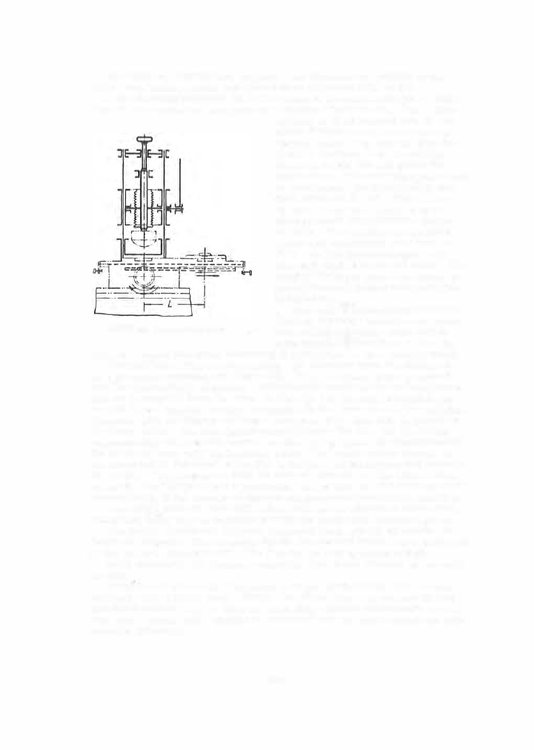
The  figures ,  ins criptions ,  symbols ,  and  divisions  are  printed  on  the 

dials  using bench presses and  india- rubbe r  cylinders  (Figure  55 ). 

A  die  carrying p rinte r ' s  ink in  its  recess  is  mounted  on the press  table .  

The  dial i s  mounted  on  a  support  at  a  distance 

from  the  die .  The  rubber 

FIGURE 55.  Press for dial printing 

cylinder is  first lowered  onto  the  die 

where it  takes  a  negative  imprint of 

the  dial  scale .  The  table  is  then  dis­

placed a  dis tance 

and the  cylinder 

descends  on  the  dial  and prints  the 
entire  s cale .   The printing is performr:d 

in  two  stage s ,   with intermediate  and 

final  drying  at  40-45°.  The  ink must 

be laid in a  uniform  layer,  4  to  5 

fl 

thick,  without  discontinuities  (gaps ) 

or  leaks .  The  printing  is  inspected 

under a  5 X  magnifying glass  and  the 

dials  are  then  varnished  again  with 

the  same  BMK - 5  resin and  dried.  The 

finished  dials  are  packed in  stacks  to 

prevent  damage  during  transportation 
and  storage . 

Dials  with a  black glossy field  and 

white  or  luminous  symbols  are  manu­

factured by a  process  which differs 

from  that described above  in that the 

dials  are  dipped into baths  containing  special  mixtures  (see Chapter  Nine ). 

The  printing of figures and  symbols  with luminous  paste  is  performed 

on a  pneumatic  printing set (Figure  56 ).  Thick 

uminous  paste  is poured 

into the upper cylinder of the s et.  A lid with rubber padding closes the cylinder 

and air is supplied from  the  s ide.  A  die with  7  to  10 small  through holes 

in  each figure  (symbol )  contour  is mounted  in  the  lower part of the  cylinder. 

The  dial,  with  the  figures and signs  printed  on  it  in  white  ink,  is placed  on 

the  lower  table .   The  table  is  fed manually under  the  die,  and  then lifted 

pneumatically  and pressed against  the  die .  Air pres sure  is  simultaneously 

fed  to  the  cylinder  with the  luminous  paste .  The  paste  pass e s  through  the 

die  holes  and  is  deposited  on  the  dial  in the  form  of the  figures  and  symbols 

in  the  die .  The  pressure  is held for  several  seconds  and the table is then 

lowere d .   This  machine  has  a  production  rate of  1 2 0 0  to  1 5 00  dials  per  shift , 
independently of  the  number  of figures  and symbols to be printed on each dial . 

The  manufacture  of  dials  with  either  pink  mat  or  embossed silver field, 

and  gilded  relief figures  is  different from  the  processes  described above . 

The  raised figures  and  field  are  embossed in  one  stroke  on  knuckle  or 

frictional presses .  The  recesses  for  the  figures  and  s ymbols  are  embossed 
in the die by a  smooth punch .   The  figures are  0 . 2 5  to  0 . 3 5  mm high. 

A fter emboss ing the  dials are  annealed,  etched  and  trimmed on the  outer 

contour . 

Watch hands  are  made  of polished  1 0 M  low- carbon  steel  strip  or  from 

polished  LS6 3 - 3  brass  strip .  Hands ,   like  dials,  are  very diverse in  shape 

and finish (Figure  5 7 ).  A  different  hand  shape  usually  corresponds  to  each 
dial shape  (Figure  5 8 ) .   Hands  are  classified into  two  types - blind  and  with 

windows  (skeleton ), 

3 2 1 

Hands  with a  drawn hub  are blanked  in a die by the  scrap- blanking method 

(Figure  59 )  on an automatic  press .  Minute  hands  without hubs are  directly 

blanked .   The  manufacture  of hour and  minute  hands  is  identical  in other 

respects . 

FIGURE 56.  Machine for printing  dials with luminous paste 

The  blanked hands  are  straightened  on  a  steel plate,  and  then carburized, 

hardened and tempered in order to make their  surface hard and elastic . 

C a r  b u r  i z i n g   is  used when a combination of a tough  core and  high  sur­

face  hardnes s  is  require d .   The  carburizing o f  hands made  of grade-1 0  steel 

is  conducted in electric furnaces;  6 00 - 8 0 0  pieces  are  placed  in  a  container 

together with the carburizing compound  ( 9 5 %  charcoal and 5 o/o  soap powder ); 

and  the  container  is  closed hermetically. 

FIGURE 57.  Hand  shapes 

FIGURE 58.  Dial and hands 

322 

FIGURE 59.  Blanking hands by the scrap-blanking method 

FIGURE 60.  Seconds hand 

FIGURE 61 .  Hand  with a spherical surface 

3 2 3  

The  hands  are  held  in  the  furnace  at  8 0 0  to  82 ooc  for 4 5  to  5 0  min  and 

are  then  quenched  in  oil  either  directly  or after  air-cooling and  reheating. 

Tempering is performed  at  temperatures between  350 and 48 0°C  pro­

ducing a  hardness  between 

Rc 

36 and Rc  4 6 .   The  exact tempe rature  depends 

on  the type of hand,  and  the holding time is between 4 0  and  6 0  min. 

Heat treatment is  followed by random  testing (bending and breaking ) for 

the determination of the elastic p roperties  and microstructure .  The hands 
are  next drum - tumbled with abrasives  and leather s c raps,  and  was hed in 

organic  solvents  (Standard N- 34 1 8 ,   Appendix 1 0 ).  Polishing,  performed 
on  S- 42A  machines by felt  disks  charged with grinding and polishing pastes 

follow. 

The  well - polished and  de greased hands  are  placed on  a  stainles s - s teel 

support  and  are  charged into  an  electric  crucible  furnace,  where  they  are 

held for 2 - 3  min at  3 7 0 - 3 9 0°C .  The  hands  are  under observation  and  the 

moment a blue annealing color  appears ,  they are  quickly withdrawn from 

the  furnace,  shaken off the  support onto a  piece  of paper and  cooled  in air .  

Blueing and  cooling i s  followed b y  washing i n  a  soapy solution,  after which 

the  hands are  rinsed in  cool  running water  and  in  alcohol,  and  dried  in a 

cupboard . 

The  seconds  hand  is  composed  of  the  hand proper ( 1 )  and  the  hub  (2 ) 

(Figure  6 0 ) .   The  hand  ( 1 )  is  made  of  l OT  steel  by  a  process  identical  with 

that  for  the  manufacture  of  the  minute  hand  and,  when  finished,  is  fitted on 

a  brass  hub  and  staked .   The  ope ration is performed o n  a  bench pres s . 

Hour and  minute  hands  having a  convex s urface  (Figure  6 1 )  are formed 

and  trimmed after blanking.  Steel hands  which  have  to be  coated  with 

various  paints,  luminous  paint  or  with  gold,  are  subjected to  the  entire 

cycle  of operations  described above,  beginning with  the blanking and  ending 

with face polishing.  The final  operations  depend  on  the  particular  require­

ments  of the design  drawing and the technical  specifications . 

3 2 4  


Content   ..  79  80  81  82   ..