Technology of watch production - part 51
 

  Index      Books     Technology of watch production (Tarasov) 1964 year


Search            


Content   ..  49  50  51  52   ..


Technology of watch production - part 51


angular pitch  of  the  index plate  or  in  the  work-spindle  change-gear t rain in 
hobbing machines . 

The  angular -pitch  accuracy  of  index plates  is  ± 0°2 

'

.  This error increases 

to  ± 0°3 1  during the life  of the plate due to the  nonuniform  wear on its  work­
ing surfaces . 

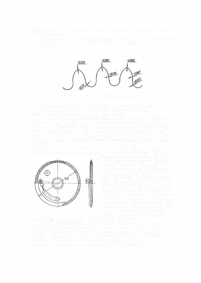
FIGURE  32 .  Blunting of the tooth tip in wheel hobbing 

The  accuracy of  the  work-spindle  change-gear  train  of  the  m odel  T-84, 

5 3 0 ,   and  similar machines  is  also  ±0°3 1 •   It is  thus  seen that,  from  this 

point  of  view,  both  methods  give  identical  results . 

The  two  methods  are  equivalent with  respect to  the  other  accuracy para­

mete rs  as  well :  p rofile,  tooth thicknes s ,   outside  diameter,  and  run- out. 

The run- out depends  to  a  small extent on the method us ed.  When  using the 

form- milling  method,  the  cutter must be  accurately set  relative  to  the  part 

center - the center plane o f  the cutter must  pas s  through the axis of  revolu­
tion of the blank.  No s uch positioning is  required when using the  generation 

method. 

R o u n d i n g - u p   is a fitting operation.  It is  used in thos e  cases  where it is 

required to  reduce the wheel  run- out,  or its  outs ide  diameter.  The  S- 6 1  

FIGURE 33.  Rounding-up cutter 

machine is  used to perform  this  oper­
ation using a  special  cutter 

(

F igures 

3 3 - 34 ) .   One  third of the  cutter cir­

cumference  is  s mooth and bent out of 

the  general plane  by the value  of the 

tooth pitch o f  the  wheel being worked. 

When  the  cutter revolves,  the  end of 

the deflected s egment engages  a  tooth 

space  on the  wheel being worked  and 

indexes  it by one pitch.  The  remainder 

of the  cutter circumference has  very 

fine teeth with a  profile  identical with 

that of the wheel-tooth space.  No  hori­

zontal  or  vertical feeds  are imposed. 

The  wheel,  together with its shaft, 

revolves  freely between the  machine  c enters 

(

Figure  35 ) .  

The  necessity for  rounding-up  decreas es  with a n  increas e  i n  the  accuracy 

with which wheels  and pinions are  machined, and with an increase in the ac­

curacy of the  assembly  elements 

(

interaxial  distances  in the plates

)

.  The 

sizing of  holes  in wheels ,  based on  the  outs ide  diameter of  the  wheel,  has 

made  it possible  to  reduce the  run- out  of  wheels  to  0 . 0 1 - 0 . 0 1 5  mm,  an 

accuracy sufficient for  the  normal  operation  of watch  gearing. 

2 0 1  

FIGURE  34.  S-61 machine for rounding-up wheels 

Female 

centers 

FIGURE  35.  Position diagram of rounding-up cutter 

and wheel 

INSPECTION  OF  GEARING  ELEMENTS 

Several  methods  exist  for the  inspection of the various  gearing- elements , 

each with its  specific  advantages  and  shortcomings . 

The  inspection methods  and  means  are  as  important in  production as  are 

the  machining methods  and  means .  Inspection- operation s heets  are accord­

ingly included in the  technical  documentation along with the machining-oper­

ation  sheets  by  many plants .  The  inspection methods  must obviously be 

quick,  and  the inspection means  accurate  and  easily handled. 

202 

The  various  gearing  elements  are  inspected in watch plants  by m eans  of 

contact and optical measuring methods .  The m easured  errors being small 
in absolute  value,  the  inaccuracy  of  the  m easuring m ethod itself c ons titutes 
a  considerable percentage  of the  tolerance .   Thus,  the  accuracy of profile 

inspection by means  of a  profile  projector at a  m agnification  of  1 00 X is  not 

better than  3 

1, , 

which is  30 o/o  of the  tolerance  on the  tooth p rofile  of an ac­

curacy class  2  wheel  with module between  0 . 1  and 0 . 1 5  m m .  

The  gearing  elements  listed i n  Table  2  are  inspected b y  the  inspection 

methods  and means  described below. 

Inspection  of the  external  diameter. 

The  inspection of the external  dia­

meter is  the first operation in the s equence  of inspection operations  for 

toothed-wheel  elem ents .  A ny  variation in this  diameter leads ,  as  was  ex­

plained above,  to a  corresponding shift in the basic  rack. 

The  external  diameter is  inspected,  under plant conditions ,  by m eans 

of  ring limit  gages  (Figure  36 ),  and in individual  cases by watch micro­
meters .  The advantage  of the gage - inspection method lies in the fact that 

it eliminates  the possibility  of pass ing wheels  or pinions of diameters larger 
o r  s maller than required,  and in that the numbe r  o f  teeth on the wheel or 

pinion plays  no part in the  inspection.  This  method is  als o  very quick. 

Measurement by a  watch micrometer  gives  the actual wheel dimension, 

but difficulties  are  encountered when using this method  for meas uring 

wheels  with an odd numbe r  of teeth.  This  method is  also  slower than  the 

ring- gage  method. 

FIGURE  36.  Ring gage 

Samples  of  three wheels  are  inspected from  each mandrel  (one  from 

each end and one from the middl e ) .  

I n  the  case of pinions ,  one pinion i s  taken at random  and  inspected from 

among  1 0- 1 5  produced. 

The  inspection of the  external  diameter under laboratory conditions  is 

carried out using a tool microscope. 

Measurement of the  tooth  thicknes s .  

The tooth  thickness is  measured 

using a  watch micrometer with special  inserts  or  using a  tool microscope. 

In addition,  the thickness  is  inspected by the profile projecto r  s imulta­

neously with the profile  inspection.  To that  end,  the projected tooth p rofile 
is  superimposed on the p roperly s caled design  drawing.  The  tolerance  on 

the outside  diameter J::eing small,  its  influence  on the accuracy of the mea­

surements  when using the superposition m ethod is  negligible .   The method 
of profile projector inspec tion is  also  rapid. 

2 0 3  

In  the  case  of  wheel s ,   the  thickness  of  three  teeth  is  m easured while  all 

the  teeth are inspected with pinions .  The  inspection in both cas es  is  a  ran­
dom  inspection. 

Inspection  of the  tooth profile. 

The  third  element subjected to inspection 

is  the tooth p rofile.  P rofile inspection is  always  carried out using a  profile 
p rojector with a magnification  of  5 0X or  l OOX,  and sometimes  of 2 0 0X.  The 

FIGURE  37. 

Profile projector with a 

profile p rojector  has  become the  accepted 

plant  inspection  m eans  (Figure  3 7 ).  The 
measurements  are  made  more  convenient 
and  accurate  by  drawing the  design  profiles 
on glass .  

The  tooth thickness i s  inspected s imulta­

neously with the  profile  inspection.  The 

p rofile  inspection is  of  the  random  type. 

More  accurate  measurements  are c onducted 

using a  p rofile p rojector with 2 00X magnifi­

cation and  an o versized s c reen. 

Measurement of radial  run- out. 

The 

m easurement is  conducted  either by the  con­

tact method with the aid of a  special indi­

cator,  or by the optical method,  in which 

case  the part  is  positioned on a  coordinate­
marking machine in a  special  devic e .  

The  inspection i s  performed under plant 

conditions  using indicators  with special in­

s e rts .  Low-pressure  indicators  (up  to  3 0  g) 

o f  this  type  are manufactured by the  watch 

industry with  divisions  of 0 . 0 0 1  mm  and  a 

measuring  range  of  ± 0 . 03 mm  (F igure  2 0 ,  

Chapter X). 

magnification of 

l O X , 

2 5  

x ,  

50 

x ,  

and 

l O O X  

The  m ethod  of inspection by a  coordinate­

marking machine,  used in laboratories ,   is  time-consuming.  The achievable 

accuracy,  according to  the  technical  data  of  the  m achine,  is  0 . 00 3  m m .   This 

inspection operation can als o  be  conducted by  means  of a  profile projector. 

Wheels  and pinions  are  random - inspected. 

Measurement o f  the  circular pitch. 

This  element  has  only  recently be­

gun  to be inspected.  A s  long as the  form - milling method was  the  p revalent 

manufacturing method  in use, the measurement  of the  c ircular pitch was 

unnecessary because  the  tooth  spaces were necessarily equal . 

This  system  is  inapplicable  to  bobbed wheel s ,   since  errors  in  the  many 

gear trains  of the  machine  influence both  the  tooth thicknes s  and  the  tooth­

space  width.  Therefore,  with the  wide  adoption  of the  generation  method, 

it became  necessary to  measure the circular pitch and to  determine the 

difference  between  success ive  circular  pitches  ( 

t ) .   The  measurement of 

circular pitches  is  conducted on a  coordinate - marking m achine with the  aid 

of a  circular table .   The difference 

(8 

t) is  obtained by passing from  angular 

to  linear  dim ensions  by the  formula 

&,· 

ot 

57°18' 

, pitch 

The  inspection is  of the  random  type. 

204 


Content   ..  49  50  51  52   ..