Technology of watch production - part 50
 

  Index      Books     Technology of watch production (Tarasov) 1964 year


Search            


Content   ..  48  49  50  51   ..


Technology of watch production - part 50


CUTTING  CONDITIONS  FOR  HOBBING 

Hobbing  is  used,  as  mentioned  earlier,  for  milling wheels  and,  some ­

times,  pinions . 

The  m ounting and  positioning of  pinion  and  wheel  blanks  in  the  model  5 3 0 ,  

and  T - 84  machines  i s  similar to the  m ounting and pos itioning i n  the  S - 4 0  
and  S - 5 3  machines  (see Figure  7 ). 

The  cutting speeds  and  feed  rates  are  es tablished  as  a  function  of  the 

mechanical p roperties  of  the  material,  the  dimens ions  of  the  blank  and  the 
hob  material .  The feed rate in hobbing is  expressed in millimeters  per 

revolution  of the part being hobbed and is  determined by the following for­

mula: 

S0 

== 

Cs · M"zb 

mm/ rev. 

where 

s0 

the feed in mm per blank  revolution; 

c& 

a  factor  depending on the  mechanical prope rties  of the  material; 

the  module; 

z  = 

the  number of teeth on the wheel or pinion being hobbed. 

The  values  of the factor 

C& 

and the  exponents 

and 

are given in  Table 6 .  

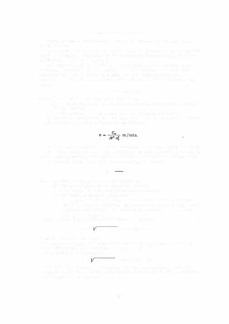
The  cutting speed is determined by the  formula 

The  values  of the  factor 

Cf} 

and the exponents 

and  y are  given in Table 7 .  

A s  a  tim e -saving m easure,  the  cutting speeds  and feed rates  recomm end­

ed for hobbing watch- gearing wheels  and pinions  are  given in Tables  1 6 - 2 0. 

The  hobbing  (basic )  time Th is  determined by  the  formula 

L·z:p_ 

n·S0 ·k  ' 

where 

Zp 

the  numbe r  of  teeth on  the  hobbed part; 

n  = 

the  speed  (rp m )  of the  single- thread hob; 

the  numbe r  of parts  machined  simultaneously; 

S0 

the  feed  per  blank  revolutions; 

l  +  [1  + [2 , 

the  travel,  where 

the  length  of  the  hobbed part 

(or of the s everal  simultaneously  machined parts ),  [1 

the cutter 

approach  (according to  the  table  in Appendix 3 ) ,   [2 

the  over­

travel  ( 1 - 1 . 5  mm). 

The  value  of  [1 can be determined from  the  formula 

[1 = cos � 

h0 (d - h0) 

l ,Stan�

(

Vz 

h0) , 

where  � 

the  hob lead angle. 

In the case of hobs ,  the  value  of the  angle �  does  not exceed 0°3 0 ' ,   as 

s een in Figure  30,  and  therefore  cos  � � 1 ,  tan  � ::::  0. 

This  reduces  the formula to 

11 

h0 (d - h0) 

(see formula  ( 3  )] 

The time  Th , calculated as  necessary for the manufacture  of one part, 

is  compared with the  available  work-spindle  speeds  and  the  time per revolu­

tion closest to  Th is  selected. 

1 9 7  

TABLE  16 

Feed 

s0 , 

mm/blank revolution,  for hobbing wheels  and pinions made of U7AV and U10A  steels 

Number of 

Module, 

mm 

wheel- or 

pinion teeth 

0.10 

0.12 

0.15 

0,20 

0.25 

0.30 

0.08 

0.085 

0.10 

0.11 

0.13 

0.14 

1 0  

0.085 

0.09 

0.11 

0.12 

0.14 

0.15 

15 

0.09 

0.10 

0.12 

0.13 

0.15 

0.17 

20 

0.10 

0.11 

0.13 

0.14 

0.17 

0.18 

30 

0.11 

0.1

2

· 

0.14 

0.16 

0.19 

0.20 

40 

0.12 

0.13 

0.15 

0.17 

0.20 

0.22 

50 

0 .13 

0.14 

0.16 

0.19 

0,21 

0.23 

60 

0.14 

0.15 

0 .17 

0 .20 

0.22 

0.24 

70 

0.145 

0.16 

0.18 

0 .21 

0.23 

0 .25 

80 

0 .15 

0.17 

0.19 

0.22 

0.24 

0.26 

TABLE  17 

Cutting speeds v ,  m/min, for hobbing wheels and pinions made of U7A V steel 

Feed 

•·  , 

Module, 

mm 

mm/blank 

0.10 

0.12 

revolution 

0.15 

0,20 

0.25 

0,30 

0. 05 

128 

118.6 

108 

96 

86.7 

80.6 

0.08 

106 

97.5 

89 

78.4 

71.4 

66 

0.10 

95 

88.4 

80.3 

71.2 

64.7 

60 

0.12 

88 

81 

74.1 

65.7 

59.6 

55.2 

0.15 

81 

75 

68.5 

60.5 

55 

51 

0.20 

71 

65 

59.4 

52.7 

47.8 

44.3 

0.25 

63.8 

59 

54.2 

48 

43.4 

40.4 

0.30 

58.7 

54.3 

49.7 

43.8 

40 

37 

0 .40 

52.2 

48 

44.1 

39.1 

35.3 

32.8 

TABLE  18 

Cutting speeds v ,  m/min, for hobbing wheels and pinions made of Ul.OA  steel 

Feed 

sJ . 

Module, 

mm 

mm/blank 

0.10 

0.12 

0.15 

0.20 

0.25 

0.30 

revolution 

Cutting speed 

tl, 

m/min 

0.05 

117 

1 08 

98.5 

87.3 

79 

73.5 

0.08 

96 

88.6 

81 

71.4 

65 

60.2 

0.10 

87 

80.5 

73.2 

64.2 

59 

54.6 

0.12 

80 

73.8 

67.5 

59.8 

54.4 

50.3 

0.15 

74 

68.3 

62.3 

55.1 

50.1 

46.4 

0.20 

64.2 

59.2 

54.1 

48 

43.6 

40.4 

0.25 

58 .2 

53.8 

49.3 

43.6 

39.6 

36.8 

0.30 

53.5 

49.4 

45.2 

40 

36 .4 

33.7 

0.40 

47.5 

43.8 

40.2 

35.6 

32.2 

29.9 

1 9 8  

TABLE  19 

Feed 

s0, 

mm/rev,  for hobbing wheels and pinions made of LS63-3-0T brass 

Number 

Module ,  mm 

of wheel-

0.1 0  

o r  pinion 

0.12 

0.15 

0.20 

0.25 

0.25 

0.40 

0.50 

teeth 

0.15 

0.17 

0.19 

0.22 

0.26 

0.28 

0.33 

0.36 

10 

0.17 

0.19 

0.21 

0.24 

0.28 

0.30 

0.36 

0.40 

15 

0.1 9 

0.21 

0.23 

0.26 

0.30 

0.33 

0.40 

0.45 

20 

0.21 

0.23 

0.26 

0.28 

0.33 

0.36 

0.45 

0.50 

30 

0.23 

0.26 

0.28 

0.30 

0.36 

0.40 

0.50 

0.55 

40 

0.26 

0.28 

0.30 

0.33 

0 .40 

0.45 

0.55 

0.60 

50 

0.28 

0.30 

0.33 

0.36 

0.45 

0.50 

0.60 

0.65 

60 

0.30 

0.33 

0.36 

0.40 

0.50 

0.55 

0.65 

0.70 

70 

0.33 

0.36 

0.40 

0.45 

0.55 

0.60 

0.70 

0.80 

TABLE 20 

Cutting speeds 

t1 

for hobbing wheels and pinions made of LS63-3-0T brass 

Feed 

So , 

mm/blank revolution 

0.1 

0.15 

0.2 

0.3 

0 .4 

0.5 

0.6 

v .  

m/min 

 '

0

 •

 0 

 0

.


205 

1 91 

181 

172 

164 

158 

153 

As  an  example ,   we will  calculate  the  cutting conditions  and the p roduction 

rate  for  a  specific  case  on the  m odel  5 3 0  s emiautomatic machine . 

It is required to hob the teeth of a  barrel  with 

z= 

80,  module 0.105 mm and material - LS63-3 brass 

(Figure 31). 

FIGURE 31.  Wristwatch barrel 

The number of parts machined simultaneously  is 

k = 

6. 

We begin by writing down the data 1vhich are to be used in the calculation.  We select from Table 19 

the feed 

s0 

0.33 mm/rev. ,  and from Table 20,  the cutting speed 

t1 = 

172 m/min.  On the basis of the 

machine data we select the hob speed 

n = 

2300 rpm.  The length of theo machined parts is (from Figure  31) 

L  = 

1 .8 

10.8 mm.  The cutter approach is,  from Appendix 3 :  /1 

2.3 mm.  We fix the overtravel as 

Lz  = 

0,  since the overtravel is  automatically provided by the turned-down diameter on the last part. 

The total travel is 

1 0.8 

2.3 

13.1 mm. 

The hobbing time corresponding to the selected conditions will be 

L · t p = 

1 3.1 · 80 

-

· So · 

2300 · 0.33·6 

0·23 

mm .  

The additional time necessary for changing the mandrel,  starting the machine,  and other similar opera­

tions is,  according to the standards,  0.42 min,  or 0.07 min per piece. 

The calculated production rate for the machine per shift will be 

480 

min. 

600  . 

0.23 + 0.07 

pleces . 

1 9 9  

We  next compare the calculated data with the  machine  capabilities.  The nearest  value for 

s0 

is 

(from Table 13)  0.30 mm/rev. ,  the  nearest  value  of 

11 

is (from Table 14)  150.8 m/min  at 

2000 rpm. 

13.1· 80 

The actual value of T h will then 

be 

2000. 0 30•6 

0.30 min, instead of the calculated value of Th 

• 

480 

0.23 min.  The actual production rate will be 

0.30 

0.07 

1300 pieces per shift. 

C omparison of the  Form - milling and  Generation 

(Robbing)  Methods 

The  following conclus ions  were  drawn on the  basis  of  inves tigations , 

conducted in watch production,  of the accuracy and  productivity of the two 
methods  of milling teeth  on wheels  and pinions : 

1 .   The p roductivity of  the  generation m ethod is  1 . 5  to  2  times higher 

than that  of the  form -milling m ethod,  The  generation method is  inherently 

free  of idle  movements  and no loss  of time  is  incurred in  indexing,  so  that 

the  milling process  is  c ontinuous .  The basic  milling time for  milling  the 

teeth  on the  center wheel  of the  "Pobeda "  brand  wristwatches  is  0 . 1 2 3  min 

using the generation m ethod and  0 . 2 7 8  min using the form - milling method 

(in two passes ).  The piece times  are  0 . 1 9  min and 0 . 38 min,  respectively. 

The following are the  time  rates  fo r  the manufacture of formed cutters 

and hob  cutters ,  and  their  respective  service live s ,   according to data s up­

plied by s everal  watch plants : 

1 .   Formed  cutter 

2.  Hob cutter 

Time rate 

1 hour 

6- 7 hours,  50"7o taken by 

form-relieving 

Life (total) 

10-12 shifts 
20-25 shifts 

The  higher cost of  hob  cutters  is  compensated for  by their longer life 

and  the highe r productivity of the  generation method its elf. 

The  manufacturing time  rates for involute  hob  cutters  are about  2 0  o/o  less 

than  those for watch- gearing p rofile  hobs . 

The  diffulty in manufacturing watch- gearing profile  bobs  lies both in  the 

need to  attain  the  specified accuracy of  lead,  profile  and  face  run- out,  and 

in the  need  to  obtain  a  tooth  space  with  minimum  blunting radius .  The  teeth 

of  hobbed  wheels  present a  characteristic  blunting  of  the  tooth tip  (Figure 32 ). 

2 .   The  surface  quality  obtained using the  generation method is  class  8 

o r  9  and  is  better by  1  or  2  classes  than  that  obtained by the  form -milling 

method. 

Every  roughness  on the cutting edge of a  formed cutter tooth  is  repro­

duced (in the negative )  on the wheel - tooth  profile .   In the generation method, 

only thos e  roughnes s es  are reproduced which appear on the line of action 

during generation.  The surface  quality,  in both methods ,  may vary within 

the  limits  of one  class ,  depending on the  quality of sharpening. 

3 .   Among the  original  machine  errors  the facto r which has  the  largest 

influence  on the  accuracy of the  completed  gear wheel  is the error in the 

200 


Content   ..  48  49  50  51   ..