Technology of watch production - part 49
 

  Index      Books     Technology of watch production (Tarasov) 1964 year


Search            


Content   ..  47  48  49  50   ..


Technology of watch production - part 49


Feed,  mm 

per blank 

revolution 

0,1 0  

0.20 

0.30 

0 .45 

0 .75 

1 .35 

TABLE  13 

TABLE  14 

Feed  gearing 

Hob-spindle speeds and cutting speeds 

Gears 

Hob-spindle 

ZJ 

z2 

speed, rpm 

24 

84 

500 

36 

72 

700 

48 

60 

1000 

60 

48 

1400 

72 

36 

2000 

84 

24 

Technical data,  model  530  machine 

Maximum work diameter,  mm 

automatic operation 

semiautomatic  operation 

·  . . . .  

Maximum hobbing length,  mm 

. • • • . . . . . • . .  

Number of teeth hobbed 

semiautomatic operation  . . . . .  

Maximum module,  mm 

. . . • • . . . . . . . . . . . .  

Minimum module,  mm 

. . . . . . • . . . . . • . • • •  

Hob diameter,  mm 

. . • . . • . . . . . • . • . . . . . .  

Hob spindle tilt,  degrees 

. . . . . . . . • . . . . . . .  

Electric motor pmver,  kw 

. . . . . . . . . • • . . . . •  

Cutting speed, 

m/min, for 

cutter diameter 

V =  

24 mm 

37 .8 

52.8 

75.5 

1 05.5 

150.8 

25 

50 

40 

6-100 
6-300 

0.05 

25-30 

Up to 3' 

0.65 

Speed of 

electric 

motor, rpm 

1400 

1400 

1400 

2800 

2800 

Hob  cutters. 

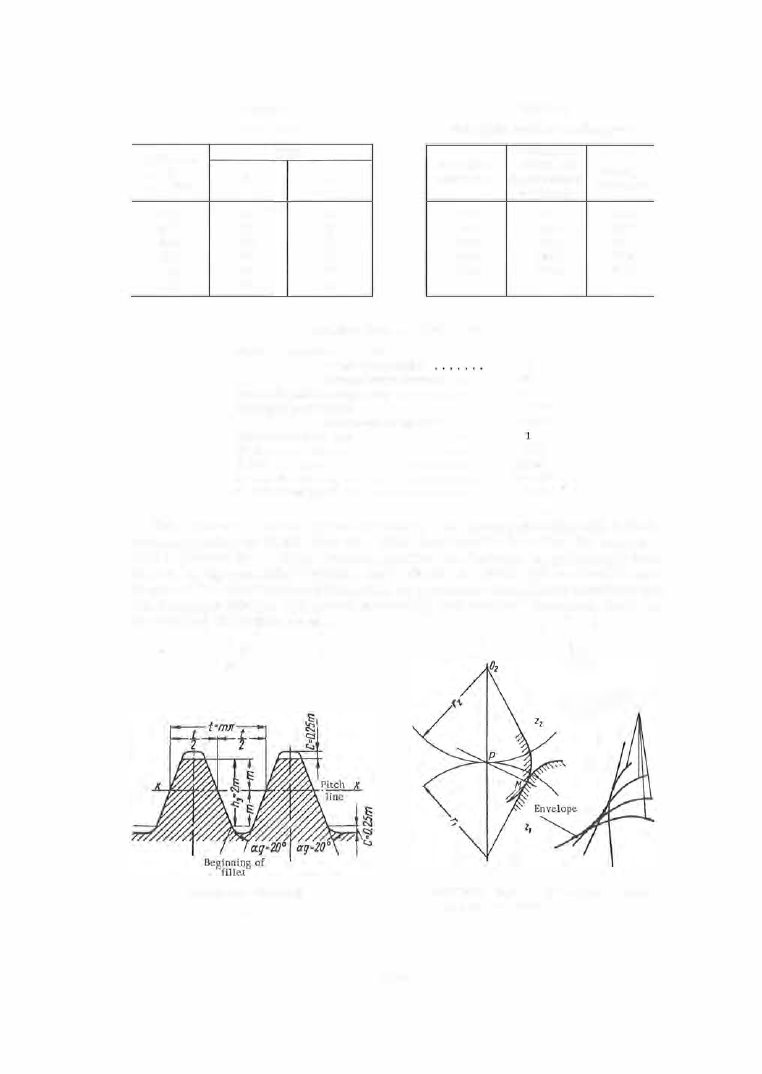
Involute  gears  are  cut by bobs  having straight- sided rack 

teeth  according to  GOST  3 0 5 8 - 4 5 .   This  tooth profile  is  called the b a s i c  

r a c k  (Figure  2 5 

). 

Watch- gearing p rofiles  are  bobbed,  as  previously m en­

tioned ,   by special  bobs  designed for each wheel .  Since this  method  is  us ed 

in  one  of the most advanced branches  of precision- instrument manufacture , 

the  design  of  bobs  is  a  practical necessity,  and  we  shall therefore  dwell  on 

the  subj ect in greater length. 

FIGURE  25.  Basic  rack 

1 9 3  

Family of plane 

curves 

F(x.IJ.C)·O 

FIGURE 26.  Envelope  of the family of plane 

curves - mated profile 

According to  the  general  theory  o f  gearing,  the  active portions  of  the 

profiles  of a  meshed pair  must be  conjugate in their  relative  motion.  If 

we imagine  the  gear 

z1 

in contact with gear z2  ,  s o  that their pitch circles 

roll without  sliding  (Figure  2 6 ,  a ),  then the successive  positions  of the gear­
tooth p rofile generate a  family of plane curves  on the fixed plane fixed to 

gear 

z2 , 

(Figure  2 6 ,  b ) .   Acco rding t o  the  general  theo ry  o f  gearing,  the 

envelope  of  this  family of  curves  is  the  mating  gear-tooth profile ,   desired 

s ince :   1 )   each point on the  envelope i s  a  point o n  one  of the  curves  of the 

family of curves ,  and  , 

2 )   each point  on  the  envelope  is  the  limiting position  of  the  intersection 

of two  adjacent curves  of the family when they are  drawn infinitely near  to 

one another. 

A s  the  hob  revolves  (see Figure  2 1 )  its  tooth p rofile  generates 

family 

of plane  curves  on  the  fixed plane  connected with the  gear being milled. 

The envelope  of this  family is  the  mating gear-tooth  profile and the  envelope 

of the  family of curves  generated by the  gear-tooth p rofile  is  the  hob p rofile. 

Therefore,  the  determination  of the p rofile of the  hob  tooth reduces  to find­

ing the  envelope of the  family  of c urves  of the  gear tooth when the pitch 

circle  of the  gear rolls  without sliding on the  pitch curve of the  rack. 

Several plotting methods  exist for obtaining the mating tooth p rofile of 

the  hob .  The  most widely used among them  are the  m ethod  of  graphical 

generation and the  graphical-analytical  method. 

The  m ethod of graphical  generation is  the  simplest and most easily vis ­

ualized  of  all  the  graphical  methods .  It  not  only  makes it possible  to  plot 

easily and  rapidly the  desired profile,  but is  suitable  for checking the  re­

s·ults  against the  initial  profil e .  

FIGURE  27.  Gear-tooth profile 

The  procedure is  as  follows :  the  tooth-space profile  of  the  gear  is  drawn 

to  a  large  s cale  on a  sheet of pap er .   The  pitch  circle is  divided  into  s e veral 

equal parts ,  and  the  points  of  division are numbered as  s hown in  F igure  2 7 .  
Radial  straight lines  are  drawn  through  the  division points .  A  s traight line 
is  drawn  on tracing paper (Figure  2 8 )  and taken as  the hob  pitch line .  This 

straight line is  divided  into  parts  o f  length  e qual  to  that  o f  the  arcs  of  the 

pitch  circle  between the  division points  and  the points  obtained  are numbered 
in the same way as  on the pitch circl e .   Perpendiculars  t o  the s traight line 

are  drawn at the points  of division.  The tracing paper is  then s uperimposed 

on the  sheet in s uch a  way that the  zero  point and the perpendicular on the 
tracing paper c oincide with the  zero  p oint and  the  radial  straight line  on the 

sheet.  The  tooth - space  profile is  then  drawn  on the  tracing paper.  Next, 

1 94 

the  corresponding points  to  the  right  and  left  on  the  two  sheets  are  cons e ­

c utively b rought  into  coincidence,  and the  tooth space profile i s  drawn  each 
time  on the  tracing paper. 

Hob-tooth profile 

li 

Basic  profile of cutter 

FIGURE 

28. 

Hob-tooth profile 

The  envelope  of  the  family of  curves obtained  is  the  required hob-tooth 

p rofile .  The plotting of the  required p rofile  reduces  to  s electing the  arc 

radii for  each portion  of the  envelop e .   The  correctness  of the profile ob­

tained  is  checked by a  revers e  generation.  The pitch circle  of the gear is 

dr.awn  on the  tracing paper,  divided into the s am e  number of parts  as in  the 

preceding cas e ,   and the tracing paper is  then  s uperimposed on the  sheet. 

By drawing the profile of the hob tooth  in every pos ition one  obtains  a  family 
of c urves  whos e  envelope  must  correspond to the  original  gear tooth-space 

p rofil e .   The  results  are checked by s uperimpos ing the  tracing paper on 

the initial p rofile  drawn  on the sheet.  The  method of graphical  generation 

has  a  shortcoming in that it is  difficult to  draw the  pitch  circle  on the  sheet 

to  a  large  scale.  Figure  29  shows  the profile  of a hob tooth,  designed  by 

the  m ethod of graphical generation,  for hobbing a  pinion with 

z  = 

and 

m = 

0 . 09 9 m m .  

T h e   g r a p h i c a l - a n a l y t i c a l   m e t h o d  i s  us ed in  cas es  where it 

is  necessary  to  plot the  p rofiles  to  a  large  s cale .   I t  consists  basically in 

plotting the  pitch circle  of  the  gear as  points  whose coordinates  are  cal­

culated analytically,  and  drawing the  p rofile  graphically from  the  given 
radius .  The  mating hob-tooth profile  is  plotted  by the  m ethod  of graphical 

generation. 

A  typical hob design  for hob bing wheels  of module  0. 05 to  0 .  3 mm is 

given in  Figure  30.  It s hould be noted that  the  lead  angle  is  0° 1 5 '  to  0°30 ' .  

The  p rofile o f  the  tooth in the  normal  plane  can  therefore be  considered 

identical  to its profile  in  the  axial plane .  This s ubs titution will be  unaccept­

able  for lead angles above  0°3 0 ' '   as  the differenc e  in profiles  will  then be 

considerable .  

1 9 5  

FIGURE  29.  Hob-tooth profile for hobbing  pinions with 

z = 

8, 

m =  

0.099 mm 

FIGURE  30.  Dimensions of a watch-gearing­

profile hob 

The  following  maximum  manufacturing e rrors  are  allowed according to 

the  specifications  for hobs  of module  0 . 0 5  to  0 . 3  mm  (Table  1 5 ). 

TABLE  1 5  

Tolerances and deviations i n  hob manufacture 

Cutter errors 

Outside-diameter run-out 

. • • . • • • • • . . . •  

Tooth-face run-out 

• • • •  

• • • • •  

• • • •  

Lead variation per turn 

• 

• • • • • • • • • • • •  

Total lead variation for five turns 

. . • . . • . • 

Profile deviations: 

a) module smaller than 0.15 mm 

.

. . .

.

b) module between  0.15 and  0.3mm 

.

. .

Tooth-space bottom blunting radius 

.

.

. .

Permissible errors,  mm 

Class A 

Class  B 

0.01 

0.02 

0.005 

0.010 

±0.002 

± 0 .003 

±0.005 

± 0,008 

0.003 

0.005 

0.004 

0.007 

0.01 

0.015 

Hobs  are form -relieved in  special  machines .  Since  watch- gearing mo­

dules  have  calculated  values  with  three  decimal  figures  (thus ,  the  module 

of the  fourth wheel of the  "Pobeda" b rand watches  is m 

0 . 0 9 9 mm ),  the 

pitch  adjustment of the machine  is  realized by  means  of a  special  device 

with a  reading accuracy of  0 . 0 0 1  mm .  The  form- relieving is  performed 

in three operations :  initial  roughing,  final  roughing,  and finishing.  The 

allowance  for  finish form -relieving is  0 . 01 mm per  side . 

The  time  norm  for the  m anufacture  of  a  hob  is  6  to  7  hours ,  with  3 . 5  to 

4  hours  of  this  time  taken by form - r elieving. 

The  life  of  a hob b efore  regrinding is ,  when  milling brass gears ,  8  to 

1 0  milling hours . 

1 9 6  


Content   ..  47  48  49  50   ..