Cessna 208B Grand Caravan EX. Airplane Flight Manual (2012) - page 7
SECTION 8
CESSNA
AIRPLANE HANDLING, SERVICE
MODEL 208B 867 SHP
AND MAINTENANCE
GARMIN G1000
GROUND HANDLING (Continued)
TIEDOWN
Proper tiedown procedure is the best precaution against damage to the
parked airplane by gusty or strong winds. To tiedown the airplane
securely, proceed as follows:
1. Head the airplane into the wind, if possible.
2. Set the parking brake.
CAUTION
Do not set the parking brake during cold weather when
accumulated moisture may freeze the brakes or when
the brakes are overheated. If the brakes are not
utilized, chock the nose and main wheels to prevent
airplane movement.
3. Install the control wheel lock and engage the rudder lock.
4. Set aileron and elevator trim tabs to neutral position so that tabs
fair with control surfaces.
5. Install pitot tube cover(s), if available.
6. Secure ropes or chains of sufficiently strong tensile strength to
the wing tiedown fittings and secure to ground anchors.
7. Attach a rope or chain to the tail tiedown, and secure to a ground
anchor.
8. If additional security is desired, attach a rope (no chains or
cables) to the nose gear torque link and secure to a ground
anchor.
9. If dusty conditions exist, or the last flight of the day has been
completed, install the two engine inlet covers to protect the
engine from debris. The covers may be installed after the engine
has cooled down
(ITT indicator showing
“off scale”
temperature).
10. To prevent the propeller from windmilling, install the propeller
anchor over a blade of the propeller and secure its anchor strap
around the nose gear or to the bracket located on the lower right
hand cowl.
8-12
U.S.
208BPHCUS-00
CESSNA
SECTION 8
MODEL 208B 867 SHP
AIRPLANE HANDLING, SERVICE
GARMIN G1000
AND MAINTENANCE
GROUND HANDLING (Continued)
JACKING
When a requirement exists to jack the entire airplane off the ground, or
when wing jack points are used in the jacking operation, refer to the
208 Maintenance Manual, Chapter 7-10-0, Jacking - Maintenance
Practices, for specific procedures and equipment required.
Several jack points or jacking locations are available depending on
whether a cargo pod is installed. The nose wheel jack point is located
directly below the firewall at FS 100.0 and housed within the nose gear
strut fairing. This jack point is accessible for nose gear jacking
regardless of the installation of a cargo pod. The two fuselage jack
points are located at the main gear supports, but are not accessible
with the cargo pod installed. Their use is generally reserved for
maintenance such as main gear removal or raising the entire airplane
whenever the cargo pod is not installed.
Anytime the cargo pod is installed, if the main gear to fuselage fairings
are removed, jacks can be positioned adjacent to the sides of the cargo
pod and raised to engage the receptacle on the end of the jacks over
the head of the outboard bolt which secures the main gear attach
trunnion bearing cap (aft) on the left and right gear. These jacking
locations serve essentially the same purpose as the fuselage jack
points at the main gear supports. An additional jack point on each main
gear axle fitting is used primarily when the cargo pod is installed and it
is desired to jack a single main gear for tire replacement, etc. If desired,
jack stands with wing jack pads may be fabricated so that the front wing
spar at WS 141.2 or 155.9 on each wing may be used as jacking
locations. A tail jack must be used in conjunction with wing jacking.
(Continued Next Page)
208BPHCUS-00
U.S.
8-13
SECTION 8
CESSNA
AIRPLANE HANDLING, SERVICE
MODEL 208B 867 SHP
AND MAINTENANCE
GARMIN G1000
GROUND HANDLING (Continued)
JACKING (Continued)
CAUTION
• A tail jack stand must be used when conducting
maintenance inside the tail section, and should be
installed in most jacking operations. Be sure the
stand is suitably heavy enough to keep the tail stable
under all conditions and is strong enough to support
the airplane. Placing a jack stand under the nose
jack point
(if not used for jacking) will provide
additional stability.
• Do not use cargo pod structure for jacking or as a
blocking surface.
• Raise the airplane no more than required for the
maintenance being performed.
• Jack base must be level and jack cylinder vertical at
start of jacking operations.
In some instances (i.e. off-runway landing, collapsed gear, etc.) it may
be necessary to use overhead means to lift (hoist) the airplane, to be
followed with jacking at the jack points. Refer to the 208 Maintenance
Manual, Chapter 7-10-01, Emergency Lifting - Maintenance Practices,
and Chapter 7-10-0, Jacking - Maintenance Practices for specific
procedures and equipment required.
8-14
U.S.
208BPHCUS-00
CESSNA
SECTION 8
MODEL 208B 867 SHP
AIRPLANE HANDLING, SERVICE
GARMIN G1000
AND MAINTENANCE
GROUND HANDLING (Continued)
LEVELING
Longitudinal leveling of the airplane for weighing will require that the
main landing gear be supported by stands, blocks, etc., on the main
gear scales to a position at least four inches higher than the nose gear
as it rests on an appropriate scale. This initial elevated position will
compensate for the difference in waterline station between the main
and nose gear so that final leveling can be accomplished solely by
deflating the nose gear tire.
NOTE
Since the nose gear strut on this airplane contains an oil
snubber for shock absorption rather than an air/oil shock
strut, it cannot be deflated to aid in airplane leveling.
The airplane can also be leveled longitudinally by raising or lowering
the airplane at the jack points. Longitudinal leveling points are provided
at FS 239.05, WL 97.50 and FS 272.13, WL 97.50. Remove screws
located at leveling screw location on the left side of the fuselage just
forward of the cargo doors. Install two screws of sufficient length at
longitudinal leveling points on fuselage to provide resting points for
level. Place a spirit level on the screws, then deflate the nose gear tire
(if placed on scales) or adjust the jacks to center the bubble in the level.
The pilot’s seat rails can also be used for longitudinal leveling by
moving the pilot’s seat to the most forward position and placing the
level on top of (and parallel to) seat rail, just aft of pilot’s seat. Observe
level indication and deflate nose gear tire (if placed on scales) or adjust
jacks to center bubble in level.
To level airplane laterally, center a spirit level across the seat rails just
aft of crew doors, removing carpet if necessary. Observe level
indication and deflate main gear tire to properly center bubble in level.
Refer to the 208 Maintenance Manual, Chapter 8-20-00, Leveling -
Maintenance Practices, for specific procedures and equipment
required.
208BPHCUS-00
U.S.
8-15
SECTION 8
CESSNA
AIRPLANE HANDLING, SERVICE
MODEL 208B 867 SHP
AND MAINTENANCE
GARMIN G1000
SERVICING
In addition to the Preflight Inspection covered in Section 4 of the POH,
complete servicing, inspection, and test requirements for your airplane
are detailed in the 208 Series Maintenance Manual. The Maintenance
Manual outlines items that require attention at regular intervals, plus
those items that require servicing, inspection, and/or testing at special
intervals.
Since Cessna Authorized Service Facilities have the training and
equipment necessary to conduct all service, inspection, and test
procedures in accordance with applicable maintenance manuals, it is
recommended that owner/operators contact the Cessna Authorized
Service Facility concerning these requirements and begin scheduling
the airplane for service at the recommended intervals.
Depending on various flight operations, your local Government Aviation
Agency may require additional service, inspections, or tests. For these
regulatory requirements, owners/operators should check with local
aviation officials where the airplane is being operated.
For quick and ready reference, quantities, materials, and specifications
for frequently used service items are as follows:
8-16
U.S.
208BPHCUS-00
CESSNA
SECTION 8
MODEL 208B 867 SHP
AIRPLANE HANDLING, SERVICE
GARMIN G1000
AND MAINTENANCE
OIL
OIL SPECIFICATION
APPROVED OILS
REFER TO PRATT & WHITNEY CANADA SERVICE BULLETIN
NO. 1001, REVISION 28, OR SUBSEQUENT REVISON FOR A
COMPLETE LISTING OF APPROVED SYNTHETIC
LUBRICATING OILS.
Figure 8-1
(Continued Next Page)
208BPHCUS-01
U.S.
8-17
SECTION 8
CESSNA
AIRPLANE HANDLING, SERVICE
MODEL 208B 867 SHP
AND MAINTENANCE
GARMIN G1000
OIL (Continued)
OIL SPECIFICATION (Continued)
OIL SYSTEM SERVICING
Pratt & Whitney Canada has determined that regular oil changes are no
longer required and engine oil is to be changed on condition. Refer to
Pratt & Whitney Engine Service Bulletin No. 1001 for information on oil
system servicing.
8-18
U.S.
208BPHCUS-01
CESSNA
SECTION 8
MODEL 208B 867 SHP
AIRPLANE HANDLING, SERVICE
GARMIN G1000
AND MAINTENANCE
OIL (Continued)
OIL CAPACITY
Total:
14 U.S. QUARTS (13.2 I)
(including filter, cooler, and hoses)
Drain and Refill Quantity:
9.5 U.S. QUARTS (9.0 l)
(approximately)
OIL QUANTITY OPERATING RANGE
Fill to within 1.5 quarts of MAX HOT or MAX COLD (as appropriate)
on dipstick. Quart marking indicate U.S. quarts low if oil is hot. For
example, a dipstick reading of 3 indicates the system is within 2
quarts of MAX if the oil is cold and within 3 quarts of MAX if the oil is
hot.
WARNING
Make sure oil dipstick cap is securely latched
down. Operating the engine with less than the
recommended oil level and with the dipstick cap
unlatched will result in excessive oil loss and
eventual engine stoppage.
NOTE
To obtain an accurate oil level reading, it is recommended
the oil level be checked within 10 minutes after engine
shutdown while the oil is hot (MAX HOT marking) or prior to
the first flight of the day while the oil is cold (MAX COLD
marking). If more than
10 minutes has elapsed since
engine shutdown and engine oil is still warm, perform an
engine dry motoring run before checking oil level.
208BPHCUS-00
U.S.
8-19

SECTION 8
CESSNA
AIRPLANE HANDLING, SERVICE
MODEL 208B 867 SHP
AND MAINTENANCE
GARMIN G1000
FUEL
FUEL GRADE (SPECIFICATION) AND FUEL ADDITIVES
* It is assumed that fuel temperature is the same as Outside Air
Temperature (OAT).
** AN8 is JP-8 fuel with a reduced freeze point specified for
Antarctic operations.
Figure 8-2
8-20
U.S.
208BPHCUS-00
CESSNA
SECTION 8
MODEL 208B 867 SHP
AIRPLANE HANDLING, SERVICE
GARMIN G1000
AND MAINTENANCE
FUEL (Continued)
FUEL ADDITIVES
One of the following fuel system anti-ice additives must be added to the
fuel as noted at the following concentrations. Use of fuel anti-ice
additives is required if freezing temperatures are expected during any
part of the flight. Use of an approved Static Dissipator or Biocide is
recommended but not required.
1. MIL-DTL-27686 (EGME) or MIL-DTL-85470 (DiEGME), Type:
Anti-Ice Additive, in a concentration of 0.10 to 0.15 percent by
volume.
2. MIL-DTL-27686 (EGME) or MIL-DTL-85470 (DiEGME), Type:
Anti-Ice Additive, in a concentration of 0.10 to 0.20 percent by
volume.
3. GOST 8313 (Fluid I), Type: Anti-Ice Additive, in a concentration
of 0.10 to 0.30 percent by volume.
4. CIS TU6-10-1458
(Fluid I-M), Type: Anti-Ice Additive, in a
concentration of 0.10 to 0.30 percent by volume.
5. T1301 (SH0396-92), Type: Anti-Ice Additive, in a concentration
of 0.10 to 0.15 percent by volume.
6. DuPont Stadis 450, Type: Static Dissipator, in a concentration as
required to bring fuel up to 300 conductive units, not to exceed 1
Parts Per Million (PPM).
7. SOHIO Biobor JF, Type: Biocide, at a concentration not to
exceed 20 PPM of elemental boron (270 PPM of total additive).
8. Kathon FP, Type: Biocide, at a concentration not to exceed 100
PPM of total additive.
(Continued Next Page)
208BPHCUS-01
U.S.
8-21
SECTION 8
CESSNA
AIRPLANE HANDLING, SERVICE
MODEL 208B 867 SHP
AND MAINTENANCE
GARMIN G1000
FUEL (Continued)
FUEL ADDITIVES (Continued)
A variety of fuels may be used in the airplane. When operating in
outside air temperatures of 5°C or colder, each fuel must have an
approved anti-icing additive, incorporated or added to the fuel during
refueling.
Make sure the correct concentration of anti-icing additive is present in
the fuel if freezing temperatures are expected during any part of the
flight.
Anti-icing additive or biocide can be used to control bacteria and fungi.
The anti-ice additives EGME/DIEGME have shown, through service
experience, that they provide acceptable protection from
microorganisms such as bacteria and fungi that can rapidly multiply
and cause serious corrosion in tanks and may block filters, screens and
fuel metering equipment.
CAUTION
• JP-5 fuels per MIL-T-5624 and JP-8 fuel per MIL-T-
83133A contain the correct premixed quantity of an
approved type of anti-icing fuel additive and no
additional anti-ice compounds should be added.
• Proper mixing of EGME or DIEGME compound with
the fuel is extremely important. A concentration in
excess of that recommended (0.15% by volume
maximum) will result in detrimental effects to the fuel
tanks, such as deterioration of protective primer and
sealants and damage to o-rings and seals in the fuel
system and engine components.
• Use only blending equipment that is recommended
by the manufacturer to obtain proper proportioning.
(Continued Next Page)
8-22
U.S.
208BPHCUS-01
CESSNA
SECTION 8
MODEL 208B 867 SHP
AIRPLANE HANDLING, SERVICE
GARMIN G1000
AND MAINTENANCE
FUEL (Continued)
FUEL ADDITIVES (Continued)
PROCEDURE FOR ADDING FUEL ANTI-ICING ADDITIVE
When the airplane is being refueled, use the following procedure to
blend anti-icing additive to nontreated fuel:
1. Attach additive to refuel nozzle, making sure blender tube
discharges in the refueling stream.
2. Start refueling while simultaneously fully depressing and slipping
ring over trigger of blender.
WARNING
Anti-icing additives containing Ethylene Glycol
Monomethyl Ether (EGME) are harmful if inhaled,
swallowed, or absorbed through the skin, and will
cause eye irritation. It is also combustible. Before
using this material, refer to all safety information on
the container.
CAUTION
• Diethylene Glycol Monomethyl Ether (DIEGME) is
slightly toxic if swallowed and may cause eye
redness, swelling and irritation. It is also
combustible. Before using this material, refer to all
safety information on the container.
• Make sure the additive is directed into the flowing
fuel stream with the additive flow started after the
fuel flow starts and stopped before fuel flow stops.
Do not allow concentrated additive to contact coated
interior of fuel tank or airplane painted surface.
• Use a minimum of 20 fluid ounces of additive per
156 gallons of fuel and a maximum of 20 fluid
ounces of additive per 104 gallons of fuel.
(Continued Next Page)
208BPHCUS-00
U.S.
8-23
SECTION 8
CESSNA
AIRPLANE HANDLING, SERVICE
MODEL 208B 867 SHP
AND MAINTENANCE
GARMIN G1000
FUEL (Continued)
FUEL ADDITIVES (Continued)
PROCEDURE FOR CHECKING FUEL ADDITIVES
Prolonged storage of the airplane will result in a water buildup in the
fuel which “leaches out” the additive. An indication of this is when an
excessive amount of water accumulates in the fuel tank sumps. The
concentration of additive can be checked using an anti-icing additive
concentration test kit. Refer to 208 Maintenance Manual, Chapter 12-
11-01, Fuel - Servicing, for additional information on the anti-icing
additive concentration test kit. It is imperative that the instructions for
the test kit be followed explicitly when checking the additive
concentration. The additive concentrations by volume for EGME/
DIEGME shall be
0.10% minimum and
0.15% maximum, either
individually or mixed in a common tank. Fuel, when added to the tank,
should have a minimum concentration of 0.10% by volume.
CAUTION
If the fuel additive concentration has fallen below
0.035% by volume, the airplane should be defueled and
refueled.
(Continued Next Page)
8-24
U.S.
208BPHCUS-00
CESSNA
SECTION 8
MODEL 208B 867 SHP
AIRPLANE HANDLING, SERVICE
GARMIN G1000
AND MAINTENANCE
FUEL (Continued)
FUEL ADDITIVES (Continued)
ANTI-STATIC PROTECTION
If additional anti-static protection is desired, the following additive is
approved for use:
Dupont Stadis 450 - in a concentration as required to bring fuel up
to 300 conductive units, not to exceed 1 PPM of total additive).
BIOCIDAL PROTECTION
If additional biocidal protection is desired, an additive is permitted for
use in certain conditions. Fuel tank maintenance practices are of prime
importance in controlling microbial growth. However, other factors such
as climate, airplane design, route structure, and utilization also affect
microbial growth; therefore, occasional use of a biocide may be
required.
Biocide additive may be used on a limited basis, defined as intermittent
or non-continuous use in a single application, to sterilize airplane fuel
systems suspected or found to be contaminated by microbial
organisms. For those operators, where the need for biocide use is
dictated, Pratt & Whitney Canada recommends, as a guide, a dosage
interval of once a month. This interval can then be adjusted, either
greater or lesser as an operator’s own experience dictates. An engine
operated in private and corporate airplanes, where utilization rates are
relatively low, may use the additive continuously. The following
additives are permitted for use:
• Sohio Biobor JF - at a concentration not to exceed 20
PPM of elemental boron (270 PPM of total additive).
• Kathon FP - at a concentration not to exceed 100
PPM of total additive.
208BPHCUS-00
U.S.
8-25
SECTION 8
CESSNA
AIRPLANE HANDLING, SERVICE
MODEL 208B 867 SHP
AND MAINTENANCE
GARMIN G1000
FUEL (Continued)
FUEL CAPACITY
TOTAL FUEL
Both Tanks and Reservoir:
339.1 U.S. Gallons (1283 l)
Both Tanks:
335.6 U.S. Gallons (1270 l)
Each Tank:
167.8 U.S. Gallons (635 l)
TOTAL USABLE FUEL
Both Tanks ON and Reservoir:
335.3 U.S. Gallons (1268 l)
Both Tanks ON:
332.0 U.S. Gallons (1256 l)
Single Tank ON:
165.0 U.S. Gallons (624 l)
TOTAL UNUSABLE FUEL
Both Tanks ON:
3.6 U.S. Gallons (13 l)
Single Tank ON:
2.8 U.S. Gallons (10 l)
Maximum Fuel Imbalance:
200 Pounds (90 kg)
NOTE
To achieve full fuel capacity, fill fuel tank to the top of the
filler neck. Filling fuel tanks to the bottom of the fuel filler
collar
(level with flapper valve) allows space for thermal
expansion and results in a decrease in fuel capacity of 4.0
U.S. gallons (15 l) per side (8.0 U.S. gallons (30 l) total).
CAUTION
To obtain accurate fuel quantity indicator readings,
verify the airplane is parked in a laterally level condition,
or, if in flight, make sure the airplane is in a coordinated
and stabilized condition.
8-26
U.S.
208BPHCUS-00
CESSNA
SECTION 8
MODEL 208B 867 SHP
AIRPLANE HANDLING, SERVICE
GARMIN G1000
AND MAINTENANCE
FUEL (Continued)
FUEL CONTAMINATION
Fuel contamination is usually the result of foreign material present in
the fuel system and may consist of water, rust, sand, dirt, microbes, or
bacterial growth. In addition, additives that are not compatible with fuel
or fuel system components can cause the fuel to become
contaminated.
Before each flight and after each refueling, use a clear sampler cup and
drain at least a cupful of fuel from each inboard fuel tank sump quick
drain valve, fuel tank external sump quick drain valve, the fuel reservoir
quick drain valve (actuated by a push-pull drain control on cargo pod),
and fuel filter quick-drain valve to determine if contaminants are present
and ensure the airplane has been fueled with the proper fuel. If the
airplane is parked with one wing low on a sloping ramp, draining of the
outboard fuel tank sump quick-drain valves
(if installed) is also
recommended.
If contamination is detected, drain all fuel drain points again. Take
repeated samples from all fuel drain points until all contamination has
been removed. If, after repeated sampling, evidence of contamination
still exists, the airplane should not be flown. Tanks should be drained
and system purged by qualified maintenance personnel. All evidence of
contamination must be removed before further flight. If the airplane has
been serviced with the improper fuel grade, defuel completely and
refuel with the correct grade. Do not fly the airplane with contaminated
or unapproved fuel.
In addition, Owners/Operators who are not acquainted with a particular
fixed base operator should be assured that the fuel supply has been
checked for contamination and is properly filtered before allowing the
airplane to be serviced. Fuel tanks should be kept full between flights,
provided weight and balance considerations will permit, to reduce the
possibility of water condensing on the walls of partially filled tanks.
(Continued Next Page)
208BPHCUS-00
U.S.
8-27
SECTION 8
CESSNA
AIRPLANE HANDLING, SERVICE
MODEL 208B 867 SHP
AND MAINTENANCE
GARMIN G1000
FUEL (Continued)
FUEL CONTAMINATION (Continued)
To further reduce the possibility of contaminated fuel, routine
maintenance of the fuel system must be performed in accordance with
the Airplane Maintenance Manual. Only the proper fuel, as
recommended in this POH/AFM, should be used, and fuel additives
must not be used unless approved by Cessna and the Federal Aviation
Administration.
WARNING
• It is the pilot’s responsibility to make sure that
the airplane’s fuel supply is clean before flight.
• Do not fly the airplane with contaminated or
unapproved fuel.
• Any traces of solid contaminants such as rust,
sand, pebbles, dirt, microbes and bacterial
growth or liquid contamination resulting from
water, improper fuel type, or additives that are
not compatible with the fuel or fuel system
components must be considered hazardous.
• Carefully sample fuel from all fuel drain locations
during each preflight inspection and after every
refueling.
8-28
U.S.
208BPHCUS-00
CESSNA
SECTION 8
MODEL 208B 867 SHP
AIRPLANE HANDLING, SERVICE
GARMIN G1000
AND MAINTENANCE
LANDING GEAR
Consult the following table for servicing information on the landing gear.
SERVICING
COMPONENT
CRITERIA
Nosewheel (22 x 8.00-8, 6-Ply Rated Tire)
30.0 - 42.0 PSI
Main Wheel (8.50-10, 8-Ply Rated Tire)
53.0 - 57.0 PSI
Main Wheel (29 x 11.00-10, 10-Ply Rated Tire)
35.0 - 45.0 PSI
Brakes
MIL-H-5606 (Note 1)
Nose Gear Shock Strut
MIL-H-5606 (Note 2)
NOTE
1. Service brake fluid reservoir with MIL-H-5606 hydraulic fluid as
placarded on reservoir. Maintain fluid level between MIN and
MAX markings.
2. Keep strut filled with MIL-H-5606 hydraulic fluid per filling
instructions placard. No air pressure is required in strut.
208BPHCUS-00
U.S.
8-29

SECTION 8
CESSNA
AIRPLANE HANDLING, SERVICE
MODEL 208B 867 SHP
AND MAINTENANCE
GARMIN G1000
OXYGEN
The oxygen cylinder, when fully charged, contains either 51 cubic feet
for the 2-port oxygen system or 117 cubic foot for the 10-port or 17-port
system, of MIL-O-27210 aviator's breathing oxygen under a pressure of
1850 PSI at 21°C (70°F). Filling pressures will vary, however, due to
ambient temperature in the filling area, and the temperature rise
resulting from compression of the oxygen. Because of this, merely
filling to
1850 PSI will not result in a properly filled cylinder. Fill to
pressures indicated on the table below for ambient temperature.
OXYGEN FILLING PRESSURES
Figure 8-3
NOTE
Refer to Section 9, Supplement 6 for additional information
on the oxygen system installed on your airplane.
8-30
U.S.
208BPHCUS-00
CESSNA
SECTION 8
MODEL 208B 867 SHP
AIRPLANE HANDLING, SERVICE
GARMIN G1000
AND MAINTENANCE
GROUND DEICE/ANTI-ICE OPERATIONS
During cold weather operations, flight crews are responsible for making
sure that the airplane is free of ice contamination. Type I deice, and
Type II, Type III, or Type IV anti-ice fluids may be used to ensure
compliance with FAA regulations, which require that all critical
components (wings, control surfaces and engine inlets as an example)
be free of snow, ice, or frost before takeoff. The deicing process is
intended to restore the airplane to a clean configuration so that neither
aerodynamic characteristics nor mechanical interference
from
contaminants will occur.
WARNING
Type II, Type III, and Type IV anti-ice fluid is
designed for use on airplanes with a VR speed of 85
knots or greater. Whenever Type II, Type III, or Type
IV anti-ice fluid is applied to the airplane, the takeoff
flap setting is limited to UP and the VR is 88 KCAS
(83 KIAS). Refer to Section 2, Limitations, Type II,
Type III, and Type IV Anti-Ice Fluid Takeoff
Limitations and Section 5, Performance, Figure 5-11
and Figure 5-27, for Flaps Up Takeoff Distances and
liftoff speeds in KIAS. Figures 5-11 and 5-27, Flaps
Up Takeoff Distance charts start with the airplane’s
maximum weight for normal operations.
NOTE
It
is recommended that flight crews refamiliarize
themselves seasonally with the following publications for
expanded deice and anti-ice procedures:
• Cessna 208 Series Maintenance Manual, Chapter 12.
• FAA Advisory Circular AC135-17, dated 14 December
1994 or later.
• FAA Advisory Circular AC20-117, dated 17 December
1982 or later.
• Cessna Aircraft Company SNL 08-1 and FAA Notice
8900.196: Revised FAA-Approved Deicing Program
Updates, Winter 2012-2013.
208BPHCUS-00
U.S.
8-31
SECTION 8
CESSNA
AIRPLANE HANDLING, SERVICE
MODEL 208B 867 SHP
AND MAINTENANCE
GARMIN G1000
GROUND DEICE/ANTI-ICE OPERATIONS (Continued)
Deicing and anti-icing fluids are aqueous solutions which work by
lowering the freezing point of water in either the liquid or crystal phase,
thus delaying the onset of freezing. For this reason, they are referred to
as Freezing Point Depressant (FPD) fluids. Deicing fluid is classified as
Type I. Anti-icing fluid is classified as Type II, Type III, or Type IV.
Deicing and anti-icing with fluids may be performed as a one-step or
two-step process. The one-step deicing procedure involves using Type
I deice fluid to remove ice and slush from the airplane prior to departure
and to provide minimal anti-icing protection as provided in the Type I
holdover timetable (refer to FAA notice 8900.196, dated 8-16-12 or
later).
The procedure involves applying Type II, Type III, or Type IV anti-ice
fluid to make sure the airplane remains clean after deicing. Type II,
Type III, or Type IV fluid is used to provide longer-term anti-icing
protection. Type I, Type II, Type III, and Type IV fluids have time
limitation before refreezing begins, at which time additional deicing is
required. This time limitation is referred to as “holdover time”. Because
holdover time depends highly on a number of factors, charts can
provide only approximate estimates. It remains the responsibility of the
pilot-in-command to determine the effectiveness of any deicing or anti-
icing procedure. Refer to FAA notice 8900.196, dated 8-16-12 or later
for Type I, Type II, Type III or Type IV fluids.
CAUTION
Type I, Type II, Type III, and Type IV fluids are not
compatible and may not be mixed. Additionally, most
manufacturers prohibit the mixing of brands within a
type. However, the same spray equipment may apply
Type I and Type III fluids. Line personnel should be
supervised by the pilot in command to ensure proper
application of Type I deice, and Type II, Type III, or
Type IV anti-ice fluids.
(Continued Next Page)
8-32
U.S.
208BPHCUS-00
CESSNA
SECTION 8
MODEL 208B 867 SHP
AIRPLANE HANDLING, SERVICE
GARMIN G1000
AND MAINTENANCE
GROUND DEICE/ANTI-ICE OPERATIONS (Continued)
NOTE
Deicing fluids are not intended for use in removing snow
deposits. Snow is best removed by mechanically sweeping
or brushing it from the airplane structure. Use caution not to
damage any airplane structure or antennas when removing
snow.
Deicing may be accomplished using the ambient temperature available
from a heated hangar or by mechanical means using a glycol-based
Freezing Point Depressant (FPD) Type I fluid. A heated hangar is an
excellent option to deice airplanes and must be utilized whenever
possible. However, care must be exercised to make sure that all melted
precipitation is removed from the airplane to prevent refreezing once
the airplane is moved from the hangar to the flight line. Type I deicing
fluids should be sprayed on the airplane (with engine shutdown) in a
manner that minimizes heat loss of fluid to the air. The fluid should be
applied in a temperature range from 160°F to 180°F (71°C to 82°C)
using a solid cone pattern of large coarse droplets. Fluid should be
sprayed as close as possible to the airplane surfaces, but not closer
than approximately 10 feet if a high-pressure nozzle is used.
Application techniques for Type II, Type III, and Type IV fluids are the
same as Type I, except that since the airplane is already clean, the
application should last only long enough to properly coat the airplane
surfaces. However, Type II, Type III, or Type IV fluid is sometimes
heated and sprayed as a deicing fluid. For this case, it should be
considered a Type I fluid as the heat may change the characteristics of
the thickening agents in the fluid. Therefore, Type II, Type III, or Type IV
fluid applied in this manner will not be as effective as it would be if it
were applied at ambient temperature.
(Continued Next Page)
208BPHCUS-00
U.S.
8-33
SECTION 8
CESSNA
AIRPLANE HANDLING, SERVICE
MODEL 208B 867 SHP
AND MAINTENANCE
GARMIN G1000
GROUND DEICE/ANTI-ICE OPERATIONS (Continued)
Refer to Figure 8-4, Essential Areas To Be Deiced, for areas to spray
Type I deicing fluid, Figure 8-5, Essential Areas To Apply Anti-ice Fluid,
for areas to spray Type II, Type III and Type IV anti-icing fluid, Figure 8-
6, Deice And Anti-ice Fluid Direct Spray Avoidance Areas, for areas to
avoid spraying directly, and Figure
8-7, Deicing And Anti-icing
Application, for sequence of application.
Heated solutions of Freezing Point Depressant
(FPD) are more
effective than unheated solutions because thermal energy is used to
melt the ice, snow, or frost formations. Type I deicing fluids are used in
the diluted state, with specific ratios of fluid-to-water dependent on
ambient temperature. Type I deicing fluids have a very limited holdover
time. Refer to FAA Notice 8900.196, dated 8-16-12 or later.
CAUTION
Type I fluids should never be used full strength
(undiluted). Undiluted glycol fluid is quite viscous below
14°F (-10°C) and can actually produce lift reductions of
about 20 percent. Additionally, undiluted glycol has a
higher freezing point than a glycol/water mixture.
NOTE
• Deicing and anti-icing procedures must be closely
coordinated between the pilot in command and ground
crews, and carried out in a timely manner. Ultimate
responsibility for safety of flight rests with the pilot in
command, and any decisions to deice or anti-ice an
airplane must be accomplished under his or her direct
supervision.
• The first area to be deiced and anti-iced must be visible
from the cockpit and must be used to provide a
conservative estimate for subsequent ice accumulations
on unseen areas of the airplane before initiating takeoff.
• Due to the weight and C.G. changes that occur while
deicing the airplane, a tail stand must be placed under
the tail to prevent the airplane from tipping on its tail.
(Continued Next Page)
8-34
U.S.
208BPHCUS-00
CESSNA
SECTION 8
MODEL 208B 867 SHP
AIRPLANE HANDLING, SERVICE
GARMIN G1000
AND MAINTENANCE
GROUND DEICE/ANTI-ICE OPERATIONS (Continued)
HOLDOVER TIMETABLE (TYPE I, TYPE II, TYPE III, AND
TYPE IV FLUIDS)
NOTE
Refer to FAA Notice 8900.196, dated 8-16-12 or later for
holdover timetables.
The length of time that deicing and anti-icing fluids remain effective is
known as “holdover time”. The holdover timetables for Type I deicing,
and Type II, Type III, or Type IV anti-icing fluids are only an estimation
and vary depending on many factors (temperature, precipitation type,
wind, and airplane skin temperature). The holdover times are based on
the mixture ratio appropriate for the OAT. Holdover times start when the
last application has begun.
Guidelines for maximum holdover times anticipated by the FAA, in
coordination with Transport Canada (TC) and the SAE G-12 Aircraft
Ground Deicing Holdover Time Subcommittee generated the HOT
guidelines published in FAA Notice 8900.196 for Type I, Type II, Type III
or Type IV, and ISO Type I, Type II, Type III, or Type IV fluid mixtures.
Type I HOTs are a function of weather conditions and outside air
temperature (OAT) while the HOTs for Type II, Type III, and Type IV
fluids are primarily a function of the OAT, precipitation type and
intensity, and percent Freezing Point Depressant
(FPD) fluid
concentration applied.
NOTE
The SAE no longer publishes HOT guidelines.
(Continued Next Page)
208BPHCUS-00
U.S.
8-35
SECTION 8
CESSNA
AIRPLANE HANDLING, SERVICE
MODEL 208B 867 SHP
AND MAINTENANCE
GARMIN G1000
GROUND DEICE/ANTI-ICE OPERATIONS (Continued)
HOLDOVER TIMETABLE (TYPE I, TYPE II, TYPE III, AND
TYPE IV FLUIDS) (Continued)
CAUTION
•
Aircraft operators are solely responsible for ensuring
that holdover timetables contain current data.
•
The tables are for use in departure planning only and
should be used in conjunction with pretakeoff
contamination check procedures.
•
The time of protection will be shortened in heavy
weather conditions. High wind velocity and jet blast
may cause a degradation of the protective film. If
these conditions occur, the time of protection may be
shortened considerably. This is also the case when
fuel temperature is significantly lower than OAT.
NOTE
•
Holdover timetables in FAA Notice
8900.196, dated
11-25-09 or later do not apply to other than SAE or ISO
Type I, Type II, Type III or Type IV fluids.
•
The responsibility for the application of this data remains
with the user.
WARNING
When ground icing conditions are present, a
pretakeoff contamination check must be conducted
by the pilot in command within 5 minutes of takeoff,
preferably just prior to taxiing onto the active
runway. Critical areas of the airplane such as
empennage, wings, windshield, control surfaces,
and engine inlets must be checked to make sure
they are free of ice, slush, and snow and that the
anti-ice fluid is still protecting the airplane.
(Continued Next Page)
8-36
U.S.
208BPHCUS-00
CESSNA
SECTION 8
MODEL 208B 867 SHP
AIRPLANE HANDLING, SERVICE
GARMIN G1000
AND MAINTENANCE
GROUND DEICE/ANTI-ICE OPERATIONS (Continued)
HOLDOVER TIMETABLE (TYPE I, TYPE II, TYPE III, AND
TYPE IV FLUIDS) (Continued)
TYPE I DEICE FLUID
NOTE
• Freezing point of Type I fluid mixture must be at least
10°C (18°F) below OAT.
• Holdover time starts when last application has begun.
• Type I fluid should be sprayed on the airplane (with
engine off) in a manner which minimizes heat loss to the
air. If possible, fluid should be sprayed in a solid cone
pattern of large coarse droplets at a temperature of
160°F to 180°F. The fluid should be sprayed as close as
possible to the airplane surfaces, but not closer than 10
feet if a high pressure nozzle is used.
WARNING
When ground icing conditions are present, a
pretakeoff contamination check should be
conducted by the pilot in command within
5
minutes of takeoff, preferably just prior to taxiing
onto the active runway. Critical areas of the
airplane such as empennage, wings, windshield,
control surfaces, and engine inlets should be
checked to make sure they are free of ice, slush,
and snow, and that the anti-ice fluid is still
protecting the airplane.
208BPHCUS-00
U.S.
8-37
SECTION 8
CESSNA
AIRPLANE HANDLING, SERVICE
MODEL 208B 867 SHP
AND MAINTENANCE
GARMIN G1000
GROUND DEICE/ANTI-ICE OPERATIONS (Continued)
HOLDOVER TIMETABLE (TYPE I, TYPE II, TYPE III, AND
TYPE IV FLUIDS) (Continued)
TYPE II ANTI-ICE FLUID
NOTE
•
Freezing point of Type II fluid mixture must be at least
7°C (13°F) below OAT.
•
Holdover time starts when last application has begun.
•
Application techniques for Type II fluid are the same as
for Type I, except that since the airplane is already
clean, the application should last only long enough to
properly coat the airplane surfaces.
•
Type II fluid can be applied undiluted at ambient
temperature to a “clean” airplane within three minutes
after deicing is completed, due to the limited holdover
times of Type I deice fluid. Type II fluid is however,
sometimes heated and sprayed as a deicing fluid. For
this case, it should be considered a Type I fluid, as the
heat may change the characteristics of the thickening
agents in the fluid. Type II fluid therefore, applied in this
manner, will not be as effective as it would be if it were
applied at ambient temperature.
CAUTION
Some Type II fluids could form a thick or high strength
gel during “dry-out” and when rehydrated can freeze
restricting movement of flight control surfaces, while in
flight.
WARNING
When ground icing conditions are present, a
pretakeoff contamination check must be conducted
by the pilot in command within 5 minutes of takeoff,
preferably just prior to taxiing onto the active
runway. Critical areas of the airplane such as
empennage, wings, windshield, control surfaces,
and engine inlets must be checked to make sure
they are free of ice, slush, and snow and that the
anti-ice fluid is still protecting the airplane.
8-38
U.S.
208BPHCUS-00
CESSNA
SECTION 8
MODEL 208B 867 SHP
AIRPLANE HANDLING, SERVICE
GARMIN G1000
AND MAINTENANCE
GROUND DEICE/ANTI-ICE OPERATIONS (Continued)
HOLDOVER TIMETABLE (TYPE I, TYPE II, TYPE III, AND
TYPE IV FLUIDS) (Continued)
TYPE III ANTI-ICE FLUID
NOTE
•
Freezing point of Type III fluid mixture must be at least
7°C (13°F) below OAT.
•
Holdover time starts when last application has begun.
•
Application techniques for Type III fluid are the same as
for Type I, except that since the airplane is already
clean, the application should last only long enough to
properly coat the airplane surfaces.
•
Type III fluid must be applied undiluted at ambient
temperature to a “clean” airplane within 3 minutes after
deicing is completed due to the limited holdover times of
Type I deice fluid. However, Type III fluid is sometimes
heated and sprayed as a deicing fluid. For this case, it
should be considered a Type I fluid, as the heat may
change the characteristics of the thickening agents in the
fluid. Therefore, Type II fluid applied in this manner will
not be as effective as it would be if it were applied at
ambient temperature.
WARNING
When ground icing conditions are present, a pre-
takeoff contamination check must be conducted by
the pilot in command within 5 minutes of takeoff,
preferably just prior to taxiing onto the active
runway. Critical areas of the airplane such as
empennage, wings, windshield, control surfaces,
and engine inlets must be checked to make sure
they are free of ice, slush, and snow and that the
anti-ice fluid is still protecting the airplane.
208BPHCUS-00
U.S.
8-39
SECTION 8
CESSNA
AIRPLANE HANDLING, SERVICE
MODEL 208B 867 SHP
AND MAINTENANCE
GARMIN G1000
GROUND DEICE/ANTI-ICE OPERATIONS (Continued)
HOLDOVER TIMETABLE (TYPE I, TYPE II, TYPE III, AND
TYPE IV FLUIDS) (Continued)
TYPE IV ANTI-ICE FLUID
CAUTION
The time of protection will be shortened in heavy
weather conditions. Heavy precipitation rates, high
moisture content, high wind velocity, or jet blast may
reduce holdover time below the lowest time stated in
the range. Holdover time may be reduced when
airplane skin temperature is lower than OAT.
NOTE
•
Freezing point of Type IV fluid mixture must be at least
7°C (13°F) below OAT.
•
Holdover time starts when last application has begun.
•
Application techniques for Type IV fluid are the same as
for Type I, except that since the airplane is already
clean, the application should last only long enough to
properly coat the airplane surfaces.
•
Type IV fluid can be applied undiluted at ambient
temperature to a “clean” airplane within three minutes
after deicing is completed, due to the limited holdover
times of Type I deice fluid. Type IV fluid is however,
sometimes heated and sprayed as a deicing fluid. For
this case, it should be considered a Type I fluid, as the
heat may change the characteristics of the thickening
agents in the fluid. Type IV fluid therefore, applied in this
manner, will not be as effective as it would be if it were
applied at ambient temperature.
(Continued Next Page)
8-40
U.S.
208BPHCUS-00
CESSNA
SECTION 8
MODEL 208B 867 SHP
AIRPLANE HANDLING, SERVICE
GARMIN G1000
AND MAINTENANCE
GROUND DEICE/ANTI-ICE OPERATIONS (Continued)
HOLDOVER TIMETABLE (TYPE I, TYPE II, TYPE III, AND
TYPE IV FLUIDS) (Continued)
TYPE IV ANTI-ICE FLUID (Continued)
CAUTION
• Some Type IV fluids could form a thick or high
strength gel during “dry-out” and when rehydrated
can freeze restricting movement of flight control
surfaces, while in flight.
• Some Type IV fluids exhibit poor aerodynamic
elimination
(flow-off)
qualities
at
colder
temperatures.
• Heated areas of airplane (i.e., heated pitot tubes and
stall warning vanes) should be avoided due to the
fact that fluid may
“dry-out” into hard globular
nodules.
208BPHCUS-00
U.S.
8-41
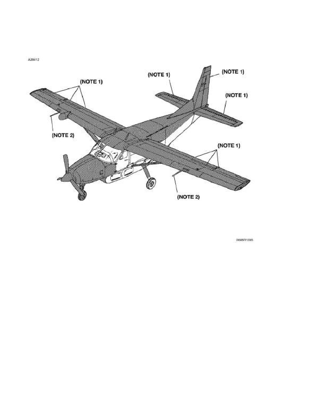
SECTION 8
CESSNA
AIRPLANE HANDLING, SERVICE
MODEL 208B 867 SHP
AND MAINTENANCE
GARMIN G1000
ESSENTIAL AREAS TO BE DEICED
SHADED AREAS INDICATE ESSENTIAL AREAS TO BE DEICED.
NOTE
1. Give special attention to the gaps between the flight controls.
All snow, ice, and slush must be removed from these gaps.
2. Remove snow, ice and slush from pitot tubes by hand only.
DIRECT SPRAY AVOIDANCE AREAS:
Engine Inlets and Exhaust, Brakes, Pitot-Static Tubes, Windshields,
Cabin Windows, and Stall Warning Vane.
Figure 8-4
8-42
U.S.
208BPHCUS-00

CESSNA
SECTION 8
MODEL 208B 867 SHP
AIRPLANE HANDLING, SERVICE
GARMIN G1000
AND MAINTENANCE
ESSENTIAL AREAS TO APPLY ANTI-ICE FLUID
SHADED AREAS INDICATE ESSENTIAL AREAS WHERE ANTI-ICE
FLUID IS APPLIED.
NOTE
Anti-ice fluid must be applied at low pressure to form a thin
film on surfaces. Fluid must just cover airplane without
runoff.
DIRECT SPRAY AVOIDANCE AREAS:
Pitot-Static Tubes, Windshields, Cabin Windows, and Stall Warning
Vane.
Figure 8-5
208BPHCUS-00
U.S.
8-43

SECTION 8
CESSNA
AIRPLANE HANDLING, SERVICE
MODEL 208B 867 SHP
AND MAINTENANCE
GARMIN G1000
DEICE AND ANTI-ICE FLUID
DIRECT SPRAY AVOIDANCE AREAS
DIRECT SPRAY AVOIDANCE AREAS:
Engine Inlets and Exhaust, Brakes, Pitot-static Tubes, Windshields,
Cabin Windows, and Stall Warning Vane.
Figure 8-6
8-44
U.S.
208BPHCUS-00

CESSNA
SECTION 8
MODEL 208B 867 SHP
AIRPLANE HANDLING, SERVICE
GARMIN G1000
AND MAINTENANCE
DEICING AND ANTI-ICING APPLICATION
NOTE
By starting the deice and anti-ice application at the left front
area of the airplane, the pilot can then get a conservative
estimate of how quickly ice forms by observation from
inside the cockpit. Because the cockpit is the first area
deiced or anti-iced, it will be the first area where ice will
form again.
Figure 8-7
208BPHCUS-00
U.S.
8-45
SECTION 8
CESSNA
AIRPLANE HANDLING, SERVICE
MODEL 208B 867 SHP
AND MAINTENANCE
GARMIN G1000
CLEANING AND CARE
PAINTED SURFACES
The painted exterior surfaces of the Cessna 208B have a durable, long-
lasting finish. Approximately 10 days are required for the paint to cure
completely; in most cases, the curing period will have been completed
prior to delivery of the airplane. In the event that polishing or buffing is
required within the curing period, it is recommended that the work be
done by someone experienced in handling uncured paint. Any Cessna
Authorized Service Facility can accomplish this work.
Generally, the painted surfaces can be kept bright by washing with
water and mild soap, followed by a rinse with water and drying with
cloths or a chamois. Harsh or abrasive soaps or detergents that cause
corrosion or scratches must never be used. Remove stubborn oil and
grease with a cloth moistened with Stoddard solvent.
To seal any minor surface chips or scratches and protect against
corrosion, the airplane must be waxed regularly with a good automotive
wax applied in accordance with the manufacturer's instructions. If the
airplane is operated in a sea coast or other salt water environment, it
must be washed and waxed more frequently to assure adequate
protection. Special care must be taken to seal around rivet heads and
skin laps, which are the areas most susceptible to corrosion. A heavier
coating of wax on the leading edges of the wings and tail and on the
cowl nose cap and propeller spinner will help reduce the abrasion
encountered in these areas. Reapplication of wax will generally be
necessary after cleaning with soap solutions or after chemical deicing
operations.
When the airplane is parked outside in cold climates and it is necessary
to remove ice before flight, care must be taken to protect the painted
surfaces during ice removal with chemical liquids. Isopropyl alcohol will
satisfactorily remove ice accumulations without damaging the paint.
However, keep the isopropyl alcohol away from the windshield and
cabin windows since it will attack the plastic and may cause it to craze.
8-46
U.S.
208BPHCUS-00
CESSNA
SECTION 8
MODEL 208B 867 SHP
AIRPLANE HANDLING, SERVICE
GARMIN G1000
AND MAINTENANCE
CLEANING AND CARE (Continued)
WINDSHIELD AND WINDOWS
The windshield and windows are constructed of cast acrylic. The
surface hardness of acrylic is approximately equal to that of copper or
brass. Do not use a canvas cover on the windshield unless freezing
rain or sleet is anticipated. Canvas covers may scratch the plastic
surface. When cleaning and waxing the windshield and windows, use
only the following prescribed methods and materials.
MAINTENANCE PROCEDURES
The following procedures provide the most current information
regarding cleaning and servicing windshields and windows. Improper
cleaning or use of unapproved cleaning agents can cause damage to
these surfaces.
CLEANING INSTRUCTIONS
CAUTION
• Windshields and windows (acrylic-faced) are easily
easily damaged by improper handling and cleaning
techniques.
• Do not use methanol, denatured alcohol, gasoline,
benzene, xylene, methyl n-propyl ketone, acetone,
carbon tetrachloride, lacquer thinners, commercial or
household window cleaning sprays on windshields
or windows.
1. Place airplane inside hangar or in shaded area and allow to cool
from heat of sun’s direct rays.
2. Using clean (preferably running) water, flood the surface. Use
bare hands with no jewelry to feel and dislodge any dirt or
abrasive materials.
(Continued Next Page)
208BPHCUS-00
U.S.
8-47
SECTION 8
CESSNA
AIRPLANE HANDLING, SERVICE
MODEL 208B 867 SHP
AND MAINTENANCE
GARMIN G1000
CLEANING AND CARE (Continued)
WINDSHIELD AND WINDOWS (Continued)
CLEANING INSTRUCTIONS (Continued)
3.
Using a mild soap or detergent, such as a dishwashing liquid, and
water to wash the windshield surfaces. Again, use only the bare
hand to provide rubbing force. A clean cloth may be used to
transfer the soap solution to the surface, but extreme care must
be exercised to prevent scratching the surface.
4.
When contaminants on acrylic windshields and windows cannot
be removed by a mild detergent, Type Il aliphatic naphtha,
applied with a soft clean cloth, may be used as a cleaning
solvent. Be sure to frequently refold cloth to avoid redepositing
contaminants and/or scratching windshield with any abrasive
particles.
5.
Rinse surface thoroughly with clean fresh water and dry with a
clean cloth.
6.
Hard polishing wax should be applied to acrylic surfaces. (The
wax has an index of refraction nearly the same as transparent
acrylic and will tend to mask any shallow scratches on the
windshield surface).
7.
Acrylic surfaces may be polished using a polish meeting Federal
Specification P-P-560 applied per the manufacturer’s
instructions.
CAUTION
When applying and removing wax and polish, use a
clean, soft cloth, such as cotton or cotton flannel.
8.
A Cessna approved rain repellent and surface conditioner may
be used to increase the natural cleaning of the windshield during
rain. Apply in accordance with manufacturers instructions.
Caution must be used not to get rain repellent on painted
surfaces surrounding the windshield.
CAUTION
REPCON is the only rain repellent conforming to
Federal Specification MIL-W-6862 that is approved to
use on Cessna Model 208 series airplanes.
8-48
U.S.
208BPHCUS-00
CESSNA
SECTION 8
MODEL 208B 867 SHP
AIRPLANE HANDLING, SERVICE
GARMIN G1000
AND MAINTENANCE
CLEANING AND CARE (Continued)
WINDSHIELD AND WINDOWS (Continued)
PREVENTIVE MAINTENANCE
CAUTION
Utilization of the following techniques will help minimize
windshield and window crazing.
1.
Keep all surfaces of windshields and windows clean.
2.
If desired, wax acrylic surfaces.
3.
Carefully cover all surfaces during any painting, powerplant
cleaning or other procedure that calls for the use of any type of
solvents or chemicals.
4.
The following coatings are approved for use in protecting
surfaces from solvent attack:
a. White Spray Lab, MIL-C-6799, Type I, Class II.
b. WPL-3 Masking Paper - St. Regis, Newton, MA.
c.
5 X N - Poly-Spotstick - St. Regis, Newton, MA.
d.
Protex
40
- Mask Off Company, Monrovia, CA and
Southwest Paper Co., Wichita, KS.
e. Protex
10VS - Mask Off Company, Monrovia, CA and
Southwest Paper Co., Wichita, KS
f.
Scotch 344 Black Tape - 3M Company
5.
Do not park or store the airplane where it might be subjected to
direct contact with or vapors from: methanol, denatured alcohol,
gasoline, benzene, xylene, MEK, acetone, carbon tetrachloride,
lacquer thinners, commercial or household window cleaning
sprays, paint strippers, or other types of solvents.
6.
Do not use solar screens or shields installed on inside of airplane
or leave sunvisors up against windshield. The reflected heat from
these items causes elevated temperatures which accelerate
crazing.
7.
Do not use power drill motor or powered device to clean, polish,
or wax surfaces.
208BPHCUS-00
U.S.
8-49
SECTION 8
CESSNA
AIRPLANE HANDLING, SERVICE
MODEL 208B 867 SHP
AND MAINTENANCE
GARMIN G1000
CLEANING AND CARE (Continued)
MATERIALS REQUIRED FOR ACRYLIC WINDSHIELDS
AND WINDOWS
MATERIAL
MANUFACTURER
USE
Mild soap or detergent
(hand
Commercially available
Cleaning windshields and
dishwashing
type
without
windows.
abrasives)
Aliphatic
naphtha Type II
Commercially available
Removing deposits that cannot
conforming
to
Federal
be removed with mild soap
Specification TT-N-95
solution on acrylic windshields
and windows.
Polishing wax: (Refer to Note 1)
Waxing acrylic windshields and
windows.
Turtle Wax (paste)
Turtle Wax, Inc.
Chicago, IL 60638
Great Reflections Paste Wax
E.I. duPont de Nemours
and
Co., (Inc.)
Wilmington, DE 19898
Classic Chemical
Slip-Stream Wax (paste)
Grand Prairie, TX 75050
Acrylic polish conforming to
Cleaning and polishing acrylic
Federal Specification P-P-560
windshields and windows.
such as:
Permatex plastic cleaner
Permatex Company,
Inc.
Number 403D
Kansas City, KS 66115
Mirror Glaze MGH-17
Mirror Bright Polish Co.
Pasadena, CA
Soft cloth, such as: Cotton
Commercially available
Applying and removing wax
flannel or cotton terry cloth
and polish.
material
Rain repellent conforming to
Rain shedding on acrylic
Federal Specification MIL-W-
windshields.
6882, such as:
UNELKO Corp.
REPCON
7428 E. Karen Dr.
(Refer to Note 2)
Scottsdale, AZ 85260
NOTE
1. These are the only polishing waxes tested and approved for
use by Cessna Aircraft Company.
2. This is the only rain repellent approved for use by Cessna
Aircraft Company for use on Cessna Model
208B series
airplanes.
Figure 8-8
8-50
U.S.
208BPHCUS-00
CESSNA
SECTION 8
MODEL 208B 867 SHP
AIRPLANE HANDLING, SERVICE
GARMIN G1000
AND MAINTENANCE
CLEANING AND CARE (Continued)
STABILIZER ABRASION BOOT CARE
If the airplane is equipped with stabilizer abrasion boots, keep them
clean and free from oil and grease, which can swell the rubber. Wash
them with mild soap and water, using Form Tech AC cleaner or naphtha
to remove stubborn grease. Do not scrub the boots and be sure to wipe
off all solvent before it dries. Boots with loosened edges or small tears
must be repaired. Your Cessna Authorized Service Facility has the
proper material and knowledge how to do this correctly.
PROPELLER CARE
Always conduct a preflight inspection and occasionally wipe the blades
with a cloth dampened with oil to clean off grass and bug stains,
minimize corrosion, and assure a longer blade life. Waxing the blades
with an automotive type paste wax on a regular basis will further
minimize corrosion. Damaged or blistered paint must be repainted.
During the preflight inspection, check the blades for nicks, gouges,
scratches, corrosion pits, etc., the propeller hub for evidence of grease
and oil leaks, and the propeller spinner for condition and security.
Repair of small nicks and scratches may be performed by qualified
mechanics in accordance with procedures specified in FAA Advisory
Circular 43.13-1A. However, whenever a significant amount of metal is
removed, or in the case of previously reworked blades that may be at or
near minimum width and thickness limits, the appropriate Hartzell
Service Manual must be consulted to determine if minimum allowable
blade width and thickness limits have been exceeded. If these limits are
exceeded, blade replacement is required. After filing and polishing, the
damaged area must be inspected by the dye penetrant method to verify
that all damage has been removed and the blade is not cracked. The
area should then be reprotected by localized application of chemical
film per MIL-C-5541 (e.g., Alodine) and repainted as necessary. Large
nicks or scratches or other damage involving such things as bent
blades, balance, diameter reduction, etc. must be corrected by an FAA
approved propeller repair station.
208BPHCUS-00
U.S.
8-51
SECTION 8
CESSNA
AIRPLANE HANDLING, SERVICE
MODEL 208B 867 SHP
AND MAINTENANCE
GARMIN G1000
CLEANING AND CARE (Continued)
ENGINE
ENGINE EXTERIOR/COMPARTMENT CLEANING
The engine exterior and compartment may be cleaned, using a suitable
solvent, in accordance with instructions in the airplane Maintenance
Manual. Most efficient cleaning is done using a spray type cleaner.
Before spray cleaning, ensure that protection is afforded for
components which might be adversely affected by the solvent. Refer to
the 208 Maintenance Manual, Chapter 12-22-01, External - Cleaning/
Painting for approved cleaning procedures and Chapter 12-21-05,
Engine Control Rod Ends
- Servicing, for information on proper
lubrication of controls and components after engine cleaning.
ENGINE COMPRESSOR WASH
The benefits of performance improvements and increased service life
of hot section parts accruing from instituting a regular compressor wash
program cannot be overemphasized. Compressor blade wash is
accomplished to remove deposit buildup accumulated on compressor
blades during normal operation. A compressor wash ring is installed on
the top of the engine adjacent to the induction air inlet screen to
facilitate this maintenance program. Refer to 208 Maintenance Manual,
Chapter 71-42-00, Compressor Blade Wash - Maintenance Practices,
for approved washing procedures.
Compressor washes can be performed by either motoring the engine
with the starter or running the engine. Depending on the nature of the
operating environment and the type of deposits in the engine gas path,
either of the two wash methods can be used to remove salt or dirt and
other baked-on deposits that accumulate over a period of time and
cause engine performance deterioration. When the wash is performed
solely to remove salt deposits, it is known as a “desalination” wash. A
wash performed to remove baked on deposits to improve engine
performance is known as a performance recovery wash. A motoring
wash is conducted at a gas generator RPM of 14-25%; the running
wash is carried out at an Ng of approximately 60% (23,000 RPM). The
water or cleaning mixture and rinsing solution, dependent on ambient
temperature, is injected at different pressure, depending on the wash
method being conducted.
(Continued Next Page)
8-52
U.S.
208BPHCUS-00
CESSNA
SECTION 8
MODEL 208B 867 SHP
AIRPLANE HANDLING, SERVICE
GARMIN G1000
AND MAINTENANCE
CLEANING AND CARE (Continued)
ENGINE (Continued)
ENGINE COMPRESSOR WASH (Continued)
Operating environment determines the nature of the wash, the
frequency, and wash method recommended. If operating in a
continuously salt-laden environment, a desalination wash is
recommended following the last flight of the day by means of the
motoring method. Occasionally, salt-laden environments may
necessitate a desalination wash each week using the motoring method.
Less severe and more general operating environments are not as
conducive to rapid deposit buildup but eventually can contribute to
performance deterioration and necessitate a performance recovery
wash at intervals of 100-200 hours. In these general environments, a
motoring wash is recommended for light soil and multiple motoring or a
running wash is suggested for heavy soil.
CAUTION
Observe engine starting cycle limits when conducting
motoring wash procedures. Refer to Section
2,
Limitations, Powerplant Limitations, for details on
Engine Starting Cycle limits.
A number of cleaning agents are recommended for addition to water to
form the cleaning solution used for compressor wash. However, the
mixture proportion of all the cleaning agents is not identical. Depending
on the prevalent ambient temperature, aviation kerosene and methanol
must be added to the cleaning solution in various proportions. The
quality of the water used is also important; any drinking quality water is
permissible for a motoring wash, but demineralized water only is
recommended for a running wash. Detailed information concerning the
cleaning mixture components, mixture formulation, recommended
quantity and application equipment can be found in Pratt & Whitney
Aircraft Gas Turbine Operation Information Letter No. 7.
208BPHCUS-00
U.S.
8-53
SECTION 8
CESSNA
AIRPLANE HANDLING, SERVICE
MODEL 208B 867 SHP
AND MAINTENANCE
GARMIN G1000
CLEANING AND CARE (Continued)
ENGINE (Continued)
COMPRESSOR TURBINE BLADE WASH
Pratt & Whitney Canada has developed a procedure for performing a
compressor turbine blade motoring wash. This technique will facilitate
the removal of contaminants from the compressor turbine blade airfoil
surfaces, thereby minimizing sulphidation attack of these surfaces. This
serves as an aid for obtaining optimum blade service life. With this
method, a water or water/methanol solution is injected directly into the
combustion chamber by way of a special spray tube which is installed
in one of the igniter plug ports. This method of engine wash does not
replace the need for a normal engine compressor wash for
performance recovery or desalination purposes.
Compressor turbine blade washing is accomplished using water of
drinking quality (potable) only at ambient temperatures of +2°C (36°F)
and above. Use a water/methanol solution at ambient temperatures
below +2°C (36°F). Refer to 208 Maintenance Manual, Chapter 71-43-
00, Turbine Blade Wash
- Maintenance Practices, for approved
washing procedures and the Pratt & Whitney, PT6A-140 Engine
Maintenance Manual, for solution strength according to ambient
temperature.
8-54
U.S.
208BPHCUS-00
CESSNA
SECTION 8
MODEL 208B 867 SHP
AIRPLANE HANDLING, SERVICE
GARMIN G1000
AND MAINTENANCE
CLEANING AND CARE (Continued)
INTERIOR CARE
The instrument panel, control wheel, and control knobs need only be
wiped off with a damp cloth. Oil and grease on the control wheel and
control knobs can be removed with a cloth moistened with Stoddard
solvent. Volatile solvents must never be used since they soften and
craze the plastic.
CAUTION
Do not use any of the following solvents for cleaning of
the interior or interior components: methanol,
denatured alcohol, gasoline, benzene, xylene, MEK,
acetone, carbon tetrachloride, lacquer thinners,
commercial or household window cleaning sprays.
When in doubt about any product, do not use it.
The plastic trim, headliner, door panels, and floor covering in the crew
area of both versions and the rear cabin headliner and sidewalls of the
Passenger Version need only be wiped off with a damp cloth. In Cargo
Versions, the sidewalls, cargo doors, and overhead in the cargo area
are not easily soiled or stained. Dust and loose dirt must be picked up
with a vacuum cleaner. Stubborn dirt can be wiped off with a cloth
moistened in clean water. Mild soap suds, used sparingly, will remove
grease. The soap must be removed with a clean damp cloth.
To remove dust and loose dirt from the upholstery and carpet, clean the
interior regularly with a vacuum cleaner.
Blot up any spilled liquid promptly with cleansing tissue or rags. Don't
pat the spot; press the blotting material firmly and hold it for several
seconds. Continue blotting until no more liquid is taken up. Scrape off
sticky materials with a dull knife, then spot clean the area.
(Continued Next Page)
208BPHCUS-00
U.S.
8-55
SECTION 8
CESSNA
AIRPLANE HANDLING, SERVICE
MODEL 208B 867 SHP
AND MAINTENANCE
GARMIN G1000
CLEANING AND CARE (Continued)
INTERIOR CARE (Continued)
Oily spots may be cleaned with household spot removers, used
sparingly. Before using any solvent, read the instructions on the
container and test it on an obscure place on the fabric to be cleaned.
Never saturate the fabric with a volatile solvent; it may damage the
padding and backing materials.
Soiled upholstery and carpet may be cleaned with foam type detergent,
used according to the manufacturer's instructions. To minimize wetting
the fabric, keep the foam as dry as possible and remove it with a
vacuum cleaner.
The protective plywood floor panels (if installed) and aft bulkhead
covering in the cargo area must be vacuum cleaned to remove dust
and dirt. A cloth moistened with water will aid in removing heavy soil.
Do not use excessive amounts of water, which would deteriorate the
protective floor panels.
For complete information related to interior cleaning, refer to the 208
Maintenance Manual, Chapter 12-23-01, Interior - Cleaning/Painting.
AVIONICS CARE
The Garmin GDU displays have an anti-reflective coating that is very
sensitive to skin oils, waxes, ammonia, and abrasive cleaners. Clean
the displays as described in the Garmin G1000 Cockpit Reference
Guide.
8-56
U.S.
208BPHCUS-00
CESSNA
SECTION 8
MODEL 208B 867 SHP
AIRPLANE HANDLING, SERVICE
GARMIN G1000
AND MAINTENANCE
PROLONGED OUT OF SERVICE CARE
Prolonged out of service care applies to all airplanes that will not be
flown for an indefinite period (less than 60 days) but which are to be
kept ready to fly with the least possible preparation. If the airplane is to
be stored temporarily or indefinitely, refer to the
208 Maintenance
Manual, Chapter 10-11-00, Storage - Maintenance Practices, for proper
storage procedures. The Maintenance Manual provides amplification
for the following procedures:
1. The procedure to be followed for preservation of an engine in
service depends on the period of inactivity and whether or not
the engine may be rotated during the inactive period. The
expected period of inactivity must be established and reference
made to the Engine Preservation Schedule. The preservation
carried out must be recorded in the engine maintenance record
and on tags secured to the engine. The following preservation
schedule lists procedures to be followed:
CAUTION
Under no circumstances should preservative oil be
sprayed into the compressor or exhaust ports of the
engine. Dirt particles deposited on blades and vanes
during engine operation will adhere and alter the airfoil
shape, adversely affecting compressor efficiency.
a.
0 to 7 Days - The engine may be left in an inactive state,
with no preservation protection, provided the engine is
sheltered, humidity is not excessively high, and the engine
is not subjected to extreme temperature changes that would
produce condensation.
b.
8 to 28 Days - An engine inactive for up to 28 days requires
no preservation, provided all engine openings are sealed off
and relative humidity in the engine is maintained at less than
40%. Humidity control is maintained by placing desiccant
bags and a humidity indicator on wooden racks in engine
primary exhaust duct. Suitable windows must be provided in
the exhaust closure to facilitate observation of the humidity
indicators.
(Continued Next Page)
208BPHCUS-00
U.S.
8-57
SECTION 8
CESSNA
AIRPLANE HANDLING, SERVICE
MODEL 208B 867 SHP
AND MAINTENANCE
GARMIN G1000
PROLONGED OUT OF SERVICE CARE (Continued)
c.
29 to 90 Days - An engine inactive for a period exceeding 28
days, but less than 91 days, need only have the fuel system
preserved, engine openings covered, and desiccant bags
and humidity indicators installed.
d.
91 Days and Over - An engine inactive over 90 days in the
airframe or removed for long-term storage in a container,
must, in addition to the 29 to 90 day procedure, have the
engine oil drained and unused accessory drive pads
sprayed.
2.
Place a cover over the pitot tube and install the two engine inlet
covers. To prevent the propeller from windmilling, install the
propeller anchor over a blade of the propeller and secure the
strap around the nose gear or to the bracket located on the
lower right hand cowl. Cover all other openings to prevent entry
of foreign objects.
3.
Keep the fuel tanks full to minimize condensation in the tanks.
4.
If the airplane will be out of service for
5 days or more,
disconnect the battery. If the battery is left in the airplane, it must
be removed and serviced regularly to prevent discharge. If the
battery is removed from the airplane, check it regularly for state
of charge.
5.
If the airplane is stored outside, tiedown the airplane in
accordance with the procedure in this section. Chock the nose
and main wheels; do not set the parking brake if a long period of
inactivity is anticipated as brake seizing can result.
6.
Either block up fuselage to relieve pressure on tires or rotate
wheels every two weeks to prevent flat areas on tires. Mark tires
with tape to ensure tire is placed approximately 90 degrees from
previous position.
7.
Drain all fuel drain points every 30 days and check for water
accumulation. Prolonged storage of the airplane will result in a
water buildup in the fuel which “leaches out” the fuel additive. An
indication of this is when an excessive amount of water
accumulates at the fuel drain points. Refer to Fuel Additive in
this section for minimum allowable additive concentrations.
8-58
U.S.
208BPHCUS-00
CESSNA
SECTION 9
MODEL 208B 867 SHP
SUPPLEMENTS
GARMIN G1000
SUPPLEMENTS
INTRODUCTION
The supplements in this section contain amended operating limitations,
operating procedures, performance data and other necessary
information for airplanes conducting special operations for both
standard and optional equipment installed in the airplane. Operators
should refer to each supplement to ensure that all limitations and
procedures appropriate for their airplane are observed.
A non FAA Approved Log Of Approved Supplements is provided for
convenience only. This log is a numerical list of all FAA Approved
supplements applicable to this airplane by name, supplement number
and revision level. This log should be used as a checklist to ensure all
applicable supplements have been placed in the Pilot's Operating
Handbook (POH). Supplements for both standard and installed optional
equipment must be maintained to the latest revision. Those
supplements applicable to optional equipment which is not installed in
the airplane, do not have to be retained.
Each individual supplement contains its own Log of Effective Pages.
This log lists the page number and revision level of every page in the
supplement. The log also lists the dates on which revisions to the
supplement occurred. Supplement page numbers will include an S and
the supplement number preceding the page number.
The part number of the supplement provides information on the
revision level. Refer to the following example:
208BPHCUS
-S1
-00
Revision Level of Supplement
Supplement Number
Cessna 208B, 867 SHP, Garmin G1000, U.S.
Pilot’s Operating Handbook
(Serials 208B2197 and 208B5000 and On)
208BPHCUS-00
9-1
SECTION 9
CESSNA
SUPPLEMENTS
MODEL 208B 867 SHP
GARMIN G1000
SUPPLEMENTS
INTRODUCTION (Continued)
WARNING
• Complete familiarity with the airplane and its
systems will not only increase the pilot's
proficiency and ensure optimum operation, but
could provide a basis for analyzing system
malfunctions in case an emergency is
encountered. Information in this section will
assist in that familiarization. The responsible
pilot will want to be prepared to make proper and
precise responses in every situation.
• Limitations contained in the following
supplements are FAA approved. Observance of
these operating limitations is required by Federal
Aviation Regulations.
NOTE
Some supplements contain references to equipment
manufacturers pilot’s manuals which are supplied with the
airplane at the time of delivery from the factory, or
whenever equipment is installed after delivery. These
manuals must be kept up-to-date with the latest revisions
issued by the publisher. These vendor manuals contain a
user registration form or instructions for obtaining future
revisions or changes.
9-2
208BPHCUS-00
CESSNA
SECTION 9
MODEL 208B 867 SHP
SUPPLEMENTS
GARMIN G1000
LOG OF APPROVED SUPPLEMENTS
NOTE
It is the airplane owner's responsibility to make sure that he or she has
the latest revision to each supplement of a Pilot's Operating Handbook,
and the latest issued “Log of Approved Supplements”. This “Log of
Approved Supplements” was the latest version as of the date it was
shipped by Cessna; however, some changes may have occurred, and
the owner should verify this is the latest, most up-to-date version by
contacting Cessna Customer Care at (316) 517-5800.
Supplement
Name
Revision
Equipment
Number
Level
Installed
1
TKS Ice Protection System for
0
Cargo Pod Equipped Airplanes
2
Artex ME406 Emergency
0
Locator Transmitter (ELT)
3
Artex C406-N Emergency
0
Locator Transmitter (ELT)
4
Garmin G1000 Synthetic Vision
0
Technology (SVT)
5
Configuration Deviation List
0
(CDL)
6
Oxygen System
0
7
Air Conditioning System
0
8
300 Amp Starter Generator
0
9
Bendix/King KR 87 Automatic
0
Direction Finder (ADF)
10
Cargo Doors Removed Kit
0
11
Reserved
12
Dual Garmin GMA 1347 Audio
0
Panels
13
Honeywell KHF-1050 HF
0
Transceiver with PS 440
Control Display Unit
14
115 Volt AC Power Outlets
0
15
Nickel Cadmium (NiCAD)
0
Battery
(Continued Next Page)
208BPHCUSLOG
20 June 2013
U.S.
Log-1
SECTION 9
CESSNA
SUPPLEMENTS
MODEL 208B 867 SHP
GARMIN G1000
LOG OF APPROVED SUPPLEMENTS (Continued)
Supplement
Name
Revision Equipment
Number
Level
Installed
16
Reserved
17
Reserved
18
Reserved
19
Reserved
20
L-3 Communications FA2100
0
Cockpit Voice and Flight Data
Recorder
208BPHCUSLOG
Log-2
U.S.
20 June 2013

CESSNA MODEL 208B
867 SHP - GARMIN G1000
Serials 208B2197 and 208B5000 and On
SUPPLEMENT 1
TKS ICE PROTECTION SYSTEM
FOR CARGO POD EQUIPPED AIRPLANES
SERIAL NO.
REGISTRATION NO.
This supplement must be inserted into Section 9 of the Pilot's Operating Handbook
and FAA Approved Airplane Flight Manual when the TKS Ice Protection System for
Cargo Pod Equipped Airplanes is installed.
24 MAY 2013
COPYRIGHT © 2013
CESSNA AIRCRAFT COMPANY
WICHITA, KANSAS, USA
208BPHCUS-S1-00
U.S.
S1-1
SECTION 9 - SUPPLEMENTS
CESSNA
SUPPLEMENT 1
MODEL 208B 867 SHP
GARMIN G1000
SUPPLEMENT 1
TKS ICE PROTECTION SYSTEM FOR CARGO POD
EQUIPPED AIRPLANES
Use the Log of Effective Pages to determine the current status of this
supplement.
Pages affected by the current revision are indicated by an asterisk (*)
preceding the page number.
Supplement Status
Date
Original Issue
24 May 2013
LOG OF EFFECTIVE PAGES
Page
Page
Revision
Number
Status
Number
S1-1 thru S1-78
Original
0
FAA APPROVED
S1-2
U.S.
208BPHCUS-S1-00
CESSNA
SECTION 9 - SUPPLEMENTS
MODEL 208B 867 SHP
SUPPLEMENT 1
GARMIN G1000
SERVICE BULLETIN CONFIGURATION LIST
The following is a list of Service Bulletins that are applicable to the
operation of the airplane, and have been incorporated into this
supplement. This list contains only those Service Bulletins that are
currently active.
Number
Title
Airplane Serial
Revision
Incorporated
Effectivity
Incorporated
in Airplane
FAA APPROVED
208BPHCUS-S1-00
U.S.
S1-3
SECTION 9 - SUPPLEMENTS
CESSNA
SUPPLEMENT 1
MODEL 208B 867 SHP
GARMIN G1000
TKS ICE PROTECTION SYSTEM FOR CARGO POD
EQUIPPED AIRPLANES
GENERAL
This supplement must be placed in Section 9 of the basic 208B 867
SHP Garmin G1000 Pilot’s Operating Handbook and FAA Approved
Airplane Flight Manual (POH/AFM), Revision 1, dated 22 May 2013 or
later, when the TKS Ice Protection System is installed on Cargo Pod
Equipped Airplanes. The information contained in this document
supplements or supersedes the basic POH/AFM only in those areas
listed. For limitations, procedures, performance, and loading
information not contained in this supplement, consult the basic POH/
AFM.
FAA APPROVED
S1-4
U.S.
208BPHCUS-S1-00
CESSNA
SECTION 9 - SUPPLEMENTS
MODEL 208B 867 SHP
SUPPLEMENT 1
GARMIN G1000
LIMITATIONS
The following Limitations supersede and/or are in addition to the
Limitations set forth in the basic Pilot's Operating Handbook and FAA
Approved Airplane Flight Manual:
The airplane must be operated, and its ice protection systems must be
used, as described in Normal, Abnormal and Emergency Procedures
contained in this supplement. Specific operational speeds and
performance information must be used where established for such
conditions.
REQUIRED TRAINING
Specific training for flight into known or forecast icing conditions
provided by Cessna Aircraft Company is required to be successfully
completed by the pilot in command within the preceding 12 calendar
months for any flight into known or forecast icing conditions.
Operators conducting operations under 14 CFR 121 and 14 CFR 135
may apply the grace provisions of 121.401(b) or 135.323(b) to the crew
member’s base month, as appropriate.
Completion of either of the following courses will meet this training
requirement:
Caravan Cold Wx Ops Onsite C14694 (CAC14694) and Cold WX OPS
TKS - CAC14696
Caravan Cold Wx Ops Online C14695 (CAC14695) and Cold WX OPS
TKS - CAC14696
FAA APPROVED
208BPHCUS-S1-00
U.S.
S1-5
SECTION 9 - SUPPLEMENTS
CESSNA
SUPPLEMENT 1
MODEL 208B 867 SHP
GARMIN G1000
LIMITATIONS (Continued)
PREFLIGHT
All checks and inspections as specified under Preflight Inspection,
Before Starting Engine and Before Takeoff Check contained in the
Normal Procedures section of this supplement must be satisfactorily
completed prior to flight into known or forecast icing conditions.
Takeoff is prohibited with any frost, ice, snow, or slush adhering to the
wings, tail, control surfaces, propeller blades, or engine air inlets.
WARNING
• The TKS Ice Protection System is not approved
for airplane deicing during ground operations.
Use only approved deice/anti-icing fluids to
make sure the critical surfaces are free of
contamination before flight.
• Even small amounts of frost, ice, snow, or slush
on the wing may adversely change lift and drag.
Failure to remove these contaminants will
degrade airplane performance and will prevent a
safe takeoff and climb.
FAA APPROVED
S1-6
U.S.
208BPHCUS-S1-00
CESSNA
SECTION 9 - SUPPLEMENTS
MODEL 208B 867 SHP
SUPPLEMENT 1
GARMIN G1000
LIMITATIONS (Continued)
VISUAL AND TACTILE CHECK
To assure the absence of frost, a tactile check of the wing leading edge
and upper surface, as specified in Section 4, Normal Procedures of the
basic POH/AFM, is required in addition to a visual inspection if the OAT
is below 10°C (50°F). During ground icing conditions, takeoff must be
accomplished within 5 minutes of completing the tactile check unless
the airplane is operated per 14 CFR 135.227(b)(3).
Ground icing conditions are defined as:
1. The OAT is 2°C (36°F) or below and visible moisture is present
(i.e. rain, drizzle, sleet, snow, fog, water is present on the wing,
etc.), or,
2. The OAT is 5°C (41°F) or below and conditions are conducive to
active frost formation
(e.g. clear night with a dew point
temperature/OAT difference of 3°C (5°F) or less).
The upper surface of each wing must be inspected for the condition
and presence of Vortex Generators (VGs). Each wing must have all 10
VGs installed on the upper surface. All 10 VGs must be present on
each wing or takeoff is prohibited for any flight regardless of planned
flight into known or forecast icing.
Takeoff is prohibited if frost, ice or snow may reasonably be expected to
adhere to the airplane between the tactile check and takeoff (e.g. snow
near freezing temperature with no ground deicing/anti-ice fluid
application).
FAA APPROVED
208BPHCUS-S1-00
U.S.
S1-7
SECTION 9 - SUPPLEMENTS
CESSNA
SUPPLEMENT 1
MODEL 208B 867 SHP
GARMIN G1000
LIMITATIONS (Continued)
WEIGHT LIMITS
There are no additional limitations on the maximum allowable takeoff
weight into known or forecast icing conditions for airplanes equipped
with the TKS Ice Protection System. The maximum allowable operating
weights for the airplane are:
Maximum Ramp Weight
8842 Pounds (4010 kg)
Maximum Takeoff Weight
8807 Pounds (3994 kg)
Maximum Landing Weight
8500 Pounds (3855 kg)
MINIMUM DISPATCH FLUID
Minimum ice protection fluid for takeoff for flight into known or forecast
icing conditions is 11.7 U.S. gallons (44.27 Liters)
This minimum amount of fluid allows for 45 minutes of ice protection
with the PRIMARY switch set to HIGH mode. The sight gage on the
TKS Ice Protection System tank is the only means of making sure there
is adequate fluid quantity onboard before each flight. Refer to Figure
S1-8, System Endurance Characteristics, in the Airplane and Systems
Descriptions section of this supplement to make sure proper fluid
quantity is onboard prior to each flight into known or forecast icing
conditions.
FAA APPROVED
S1-8
U.S.
208BPHCUS-S1-00
CESSNA
SECTION 9 - SUPPLEMENTS
MODEL 208B 867 SHP
SUPPLEMENT 1
GARMIN G1000
LIMITATIONS (Continued)
APPROVED ICE PROTECTION FLUID
The TKS Ice Protection System tank must be serviced with the
following fluid:
Specification DTD 406B
Trade names for DTD 406B include:
TKS Fluid (D.W. Davies)
AVL-TKS (Aviation Laboratories)
AeroShell Compound 07 (Shell)
AL-5
Fluids conforming to this specification may be mixed in the TKS Ice
Protection System tank in any proportions.
WARNING
Under no circumstances are fluids other than those
listed above to be used in the TKS Ice Protection
System. Some fluids currently used for ground de-
icing purposes contain thickening agents which
may block the porous panels. If it is known or
suspected that such a fluid has been placed in the
tank, do not operate the system.
POROUS PANEL CLEANING
Only the following fluids are approved for cleaning the TKS leading
edge porous panels:
1. Water (with soap or detergents)
2. Approved TKS Ice Protection System Fluids
3. Aviation Gasoline
4. Aviation Turbine Fuel
5. Isopropyl Alcohol
6. Ethyl Alcohol
7. Industrial Methylated Spirit
FAA APPROVED
208BPHCUS-S1-00
U.S.
S1-9
SECTION 9 - SUPPLEMENTS
CESSNA
SUPPLEMENT 1
MODEL 208B 867 SHP
GARMIN G1000
LIMITATIONS (Continued)
MINIMUM SPEEDS IN ICING CONDITIONS
The minimum airspeeds for operations in icing conditions with a FULLY
FUNCTIONAL TKS Ice Protection System operating are:
WING FLAPS UP or TO/APR
95 KIAS
WARNING
• These speeds do not apply to takeoff when using
the published POH/AFM procedure for TYPE II,
TYPE III OR TYPE IV ANTI-ICE FLUID TAKEOFF
in Section 4, Normal Procedures of the POH/
AFM.
• With a failed TKS Ice Protection System,
maintain 120 KIAS with WING FLAPS UP (110
KIAS if climbing) and refer to the Emergency
Procedure Section of this supplement.
FLAP SETTING IN ICING CONDITIONS
WING FLAPS must be UP when holding in icing conditions.
WARNING
• With ice suspected on the airframe, or operating
with OAT at
5°C
(41°F) or below in visible
moisture, do not extend WING FLAPS beyond
TO/APR for landing.
• WING FLAPS must be extended to TO/APR
during all phases of flight (takeoff and landing
INCLUDED) when airspeed is below 95 KIAS.
This does not apply to takeoff when using the
published POH/AFM procedure for TYPE II, TYPE
III OR TYPE IV ANTI-ICE FLUID TAKEOFF in
Section 4, Normal Procedures of the POH/AFM.
• The aural stall warning system does not provide
adequate stall warning in all icing conditions.
FAA APPROVED
S1-10
U.S.
208BPHCUS-S1-00
CESSNA
SECTION 9 - SUPPLEMENTS
MODEL 208B 867 SHP
SUPPLEMENT 1
GARMIN G1000
LIMITATIONS (Continued)
REQUIRED EQUIPMENT
The following equipment must be installed and fully operational for
flight into known or forecast icing conditions:
1.
Wing and wing strut leading edge porous panels
2.
Horizontal stabilizer leading edge porous panels
3.
Vertical stabilizers leading edge porous panels
4.
Propeller fluid slinger assembly
5.
TKS Ice Protection System equipment pack (tank
assembly,
pumps, filters)
6.
Windshield spray bar
7.
Heated lift detector (stall warning) vane
8.
Alternate Static Source
9.
Left and Right Pitot/Static Tube Heat System
10. Wing Ice Inspection Light
11.
Engine Driven Generator
12. Standby Electrical System
13. Engine Inertial Separator
14. Heater and Defroster
15. Hartzell Propeller: HC-B3TN-3AF/T10890CNB-2
16. Cargo Pod
17. Low Airspeed Awareness System
18. Windshield Ice Detection Light
19. Vortex Generators (10 per wing)
WINDSHIELD PUMP
The windshield pump is rated for intermittent use only.
Continuous
operation may damage the pump.
WARNING
Do not operate the windshield pump continuously
longer than 10 seconds. Allow at least 10 seconds
between operations.
FAA APPROVED
208BPHCUS-S1-00
U.S.
S1-11
SECTION 9 - SUPPLEMENTS
CESSNA
SUPPLEMENT 1
MODEL 208B 867 SHP
GARMIN G1000
LIMITATIONS (Continued)
INERTIAL SEPARATOR
If the INERTIAL SEPARATOR is set to BYPASS at any point due to
suspected or actual icing conditions, do not return it to NORMAL until
the inertial separator door has been visually inspected and verified free
of ice and ice protection fluid. Comply with the SHUTDOWN AND
SECURING AIRPLANE check of the Normal Procedures in this
supplement.
PROPELLER SPINNER
Do not operate the airplane’s engine without the propeller spinner
installed in accordance with the Cessna Model 208 Series Maintenance
Manual.
ENVIRONMENTAL CONDITIONS
Icing conditions are defined as visually detected ice, or the presence of
visible moisture in any form at an OAT of 5°C (41°F) or below.
Known icing conditions are defined by 14 CFR Part 25, Appendix C.
These conditions do not include, nor were tests conducted in, all icing
conditions that may be encountered
(e.g., freezing rain, freezing
drizzle, mixed conditions or conditions defined as severe).
WARNING
• Flight in conditions outside of 14 CFR Part 25
Appendix C is prohibited.
• The airplane must not depart or be flown into an
airport where freezing rain or freezing drizzle
conditions are being reported.
(Continued Next Page)
FAA APPROVED
S1-12
U.S.
208BPHCUS-S1-00
CESSNA
SECTION 9 - SUPPLEMENTS
MODEL 208B 867 SHP
SUPPLEMENT 1
GARMIN G1000
LIMITATIONS (Continued)
ENVIRONMENTAL CONDITIONS (Continued)
Some icing conditions not defined in 14 CFR Part 25 Appendix C have
the potential of producing hazardous ice accumulations, which (1)
exceed the capabilities of the airplane’s ice protection equipment, and/
or
(2) create unacceptable airplane performance and stall speed
increase. Pilots must be prepared to divert the flight promptly if
hazardous ice accumulations occur. Inadvertent operation in these
conditions may be detected by:
1. Unusually extensive ice is accreted on the airframe in areas not
normally observed to collect ice.
2. Accumulation of ice on the upper or lower surface of the wing aft
of the protected area.
3. Heavy ice accumulations on the windshield, or when ice forms
aft of the curved sections on the windshield.
4. Ice forms aft of the protected surfaces of the wing struts.
If these conditions are encountered, the pilot must take immediate
actions to exit these conditions.
Continued flight in icing conditions is prohibited after encountering one
or more of the following with the TKS Ice Protection System fully
functional and operating:
1. Airspeed in level flight at constant power decreases by 10 KIAS
using Maximum Cruise Power.
2. MEA or MOCA (if applicable) on current leg falls into Area “C” of
Figure S1-1, Enroute Tool For Exiting Icing, located in the
Performance section of this supplement.
Exit strategies must be determined during preflight planning.
FAA APPROVED
208BPHCUS-S1-00
U.S.
S1-13
SECTION 9 - SUPPLEMENTS
CESSNA
SUPPLEMENT 1
MODEL 208B 867 SHP
GARMIN G1000
LIMITATIONS (Continued)
AUTOPILOT OPERATION IN ICING CONDITIONS
Autopilot operation is prohibited when operating in icing conditions
which are outside the
14 CFR Part
25 Appendix C defined
Environmental Conditions listed in the Limitations section of this
supplement.
The autopilot must be disengaged when the BELOW ICING MIN SPD
flashing amber and white annunciation is activated.
The airspeeds listed in the Minimum Speeds In Icing Conditions in the
Limitations section of this supplement also apply to autopilot
operations.
MAXIMUM OPERATING ALTITUDES
Certified Maximum Operating Altitudes:
Icing Conditions
20,000 Feet
Any flight conditions with ice on the airplane
20,000 Feet
FAA APPROVED
S1-14
U.S.
208BPHCUS-S1-00
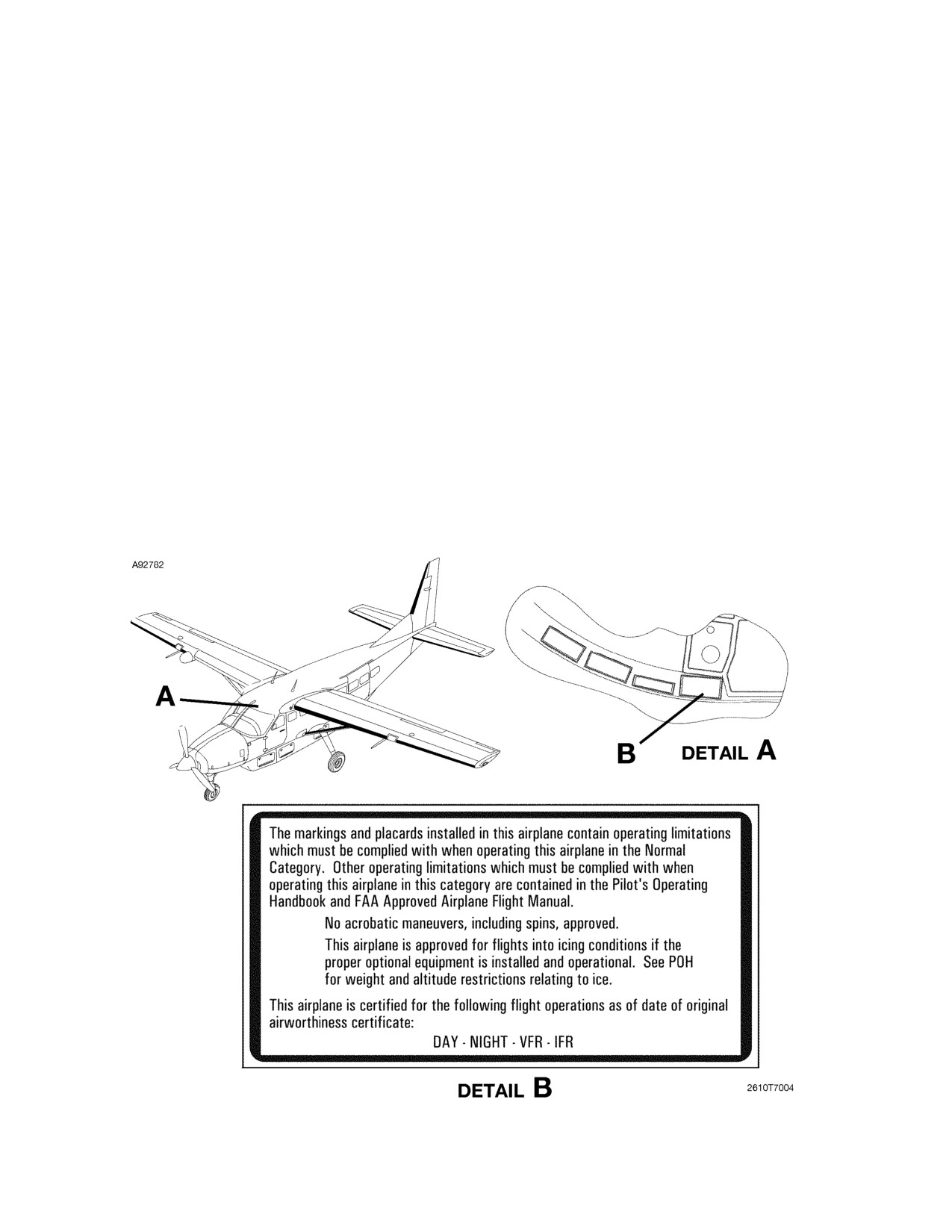
CESSNA
SECTION 9 - SUPPLEMENTS
MODEL 208B 867 SHP
SUPPLEMENT 1
GARMIN G1000
LIMITATIONS (Continued)
PLACARDS
WARNING
The following information must be displayed in the
form of composite or individual placards. As a
minimum, the exact wording of these placards is
required as specified in this section. Placard
wording can be from part numbered placards
obtained from Cessna Aircraft Company or
equivalent placards installed by an approved repair
station in accordance with normal maintenance
practices/procedures.
INTERIOR PLACARDS
FLIGHT CREW AREA
In full view of the pilot on the sunvisor or windshield trim strip on
airplanes equipped for flight into known icing:
(Continued Next Page)
FAA APPROVED
208BPHCUS-S1-00
U.S.
S1-15

SECTION 9 - SUPPLEMENTS
CESSNA
SUPPLEMENT 1
MODEL 208B 867 SHP
GARMIN G1000
LIMITATIONS (Continued)
PLACARDS (Continued)
INTERIOR PLACARDS (Continued)
FLIGHT CREW AREA (Continued)
Adjacent to the TKS Ice Protection System controls:
Above the Standby Airspeed Indicator:
(Continued Next Page)
FAA APPROVED
S1-16
U.S.
208BPHCUS-S1-00

CESSNA
SECTION 9 - SUPPLEMENTS
MODEL 208B 867 SHP
SUPPLEMENT 1
GARMIN G1000
LIMITATIONS (Continued)
PLACARDS (Continued)
EXTERIOR PLACARDS
Around the TKS Ice Protection Fluid Tank filler assembly:
(Continued Next Page)
FAA APPROVED
208BPHCUS-S1-00
U.S.
S1-17

SECTION 9 - SUPPLEMENTS
CESSNA
SUPPLEMENT 1
MODEL 208B 867 SHP
GARMIN G1000
LIMITATIONS (Continued)
PLACARDS (Continued)
EXTERIOR PLACARDS (Continued)
On the front of the TKS Ice Protection System Tank:
(Continued Next Page)
FAA APPROVED
S1-18
U.S.
208BPHCUS-S1-00

CESSNA
SECTION 9 - SUPPLEMENTS
MODEL 208B 867 SHP
SUPPLEMENT 1
GARMIN G1000
LIMITATIONS (Continued)
PLACARDS (Continued)
EXTERIOR PLACARDS (Continued)
Adjacent to TKS Ice Protection Porous Panels:
FAA APPROVED
208BPHCUS-S1-00
U.S.
S1-19
SECTION 9 - SUPPLEMENTS
CESSNA
SUPPLEMENT 1
MODEL 208B 867 SHP
GARMIN G1000
EMERGENCY PROCEDURES
RED A-ICE PRESS LOW ANNUNCIATOR COMES ON
INTERMITTENTLY WITH PRIMARY SWITCH SELECTED
TO NORM
1. PRIMARY Switch
HIGH
IF A-ICE PRESS LOW ANNUNCIATOR REMAINS ON
2. BACKUP Switch
ON
3. PRIMARY Switch
OFF
NOTE
The white A-ICE NORM annunciator will not be shown on
PFD with the BACKUP switch selected to the ON position.
4. PRI ANTI-ICE Circuit Breaker
OPEN (pull out)
(first row, fifth breaker from aft end)
5. TKS Ice Protection System
MONITOR
6. Airspeed
MAINTAIN 120 KIAS
(or greater until final approach and landing)
7. Icing Conditions
EXIT AS SOON AS POSSIBLE
IF A-ICE PRESS LOW ANNUNCIATOR GOES OFF
2. TKS Ice Protection System
MONITOR
3. Icing Conditions
EXIT AS SOON AS POSSIBLE
RED A-ICE PRESS LOW ANNUNCIATOR COMES ON
WITH PRIMARY SWITCH SELECTED TO HIGH OR MAX
FLOW SWITCH SELECTED TO AIRFRAME
1. BACKUP Switch
ON
2. PRIMARY Switch
OFF
NOTE
The white A-ICE NORM annunciator will not be shown on
PFD with the BACKUP switch selected to the ON position.
3. PRI ANTI-ICE Circuit Breaker
OPEN (pull out)
(first row, fifth breaker from aft end)
4. TKS Ice Protection System
MONITOR
5. Airspeed
MAINTAIN 120 KIAS
(or greater until final approach and landing)
6. Icing Conditions
EXIT AS SOON AS POSSIBLE
FAA APPROVED
S1-20
U.S.
208BPHCUS-S1-00
CESSNA
SECTION 9 - SUPPLEMENTS
MODEL 208B 867 SHP
SUPPLEMENT 1
GARMIN G1000
EMERGENCY PROCEDURES (Continued)
AMBER A-ICE PRESS HI OR A-ICE FLUID LO
ANNUNCIATOR COMES ON
1. Icing Conditions
EXIT AS SOON AS POSSIBLE
2. TKS Ice Protection System
MONITOR
FAILURE OF ICE PROTECTION SYSTEM OR EXCESSIVE
ICE ACCUMULATION (OBSERVED OR SUSPECTED) ON
PROTECTED AIRPLANE SURFACES
1. MAX FLOW Switch
AIRFRAME
2. Airspeed
MAINTAIN 120 KIAS
(or greater until final approach and landing)
3. Icing Conditions
EXIT AS SOON AS POSSIBLE
4. Landing Distance
MULTIPLY POH/AFM DISTANCE BY:
2.2 - WING FLAPS UP
2.1 - WING FLAPS TO/APR
5. Minimum Approach Airspeed
AT OR ABOVE:
120 KIAS - WING FLAPS UP
110 KIAS - WING FLAPS TO/APR
WARNING
• With an inoperative TKS Ice Protection System
porous panel(s), increase power to Maximum
Rated and exit icing conditions as soon as
possible. In heavy icing conditions, it may not be
possible to maintain altitude or proper glide path
on approach. In this case, it is imperative that a
safe airspeed be maintained.
• Stall speeds will increase with ice accumulation
on the wing and tail leading edges. Expect higher
than normal rates of descent with power
reduction.
(Continued Next Page)
FAA APPROVED
208BPHCUS-S1-00
U.S.
S1-21
SECTION 9 - SUPPLEMENTS
CESSNA
SUPPLEMENT 1
MODEL 208B 867 SHP
GARMIN G1000
EMERGENCY PROCEDURES (Continued)
FAILURE OF ICE PROTECTION SYSTEM OR EXCESSIVE
ICE ACCUMULATION (OBSERVED OR SUSPECTED) ON
PROTECTED AIRPLANE SURFACES (Continued)
WARNING
•
With unshed ice accumulations on the horizontal
stabilizer leading edge, do not extend flaps while
enroute or holding. When preparing to land use
the minimum flap setting required. Do not
exceed WING FLAPS TO/APR and maintain extra
airspeed consistent with available field length.
Do not retract the flaps once they have been
extended unless required for go-around. When
executing a go-around, retract flaps while
maintaining 5 to 10 knots extra airspeed.
•
Use of WING FLAPS LAND with an ice
contaminated horizontal stabilizer leading edge
can result in abnormal elevator control forces.
The pilot should be prepared to apply the
necessary elevator control inputs to maintain the
desired pitch attitude while retracting the WING
FLAPS to TO/APR.
•
The aural stall warning system does not provide
adequate stall warning in all icing conditions.
(Continued Next Page)
FAA APPROVED
S1-22
U.S.
208BPHCUS-S1-00
CESSNA
SECTION 9 - SUPPLEMENTS
MODEL 208B 867 SHP
SUPPLEMENT 1
GARMIN G1000
EMERGENCY PROCEDURES (Continued)
FAILURE OF ICE PROTECTION SYSTEM OR EXCESSIVE
ICE ACCUMULATION (OBSERVED OR SUSPECTED) ON
PROTECTED AIRPLANE SURFACES (Continued)
NOTE
•
Maintain a minimum airspeed of 120 KIAS with WING
FLAPS UP (110 KIAS minimum if climbing). If unable to
maintain this airspeed in level flight, allow altitude to
decease to maintain airspeed.
•
If there are unshed ice accumulations along the wing,
wing strut, or stabilizer leading edges during approach
and landing, follow the procedures listed under
Inadvertent Icing Encounters in Section 3, Emergency
Procedures, of the POH/AFM.
•
With an accumulation of 0.25 inch (6.35 mm) or more on
the wing leading edges, be prepared for a significantly
higher power requirement, approach speed, stall speed,
and longer landing roll.
•
If necessary, set up a forward slip for visibility through
the left portion of the windshield during the landing
approach.
•
Select the minimum flap setting required for available
field length. Use a minimum approach speed for the
selected landing configuration. With ice suspected on
the airframe, or operating at OAT 5°C (41°F) or less in
visible moisture, do not extend WING FLAPS beyond
TO/APR for landing.
FAA APPROVED
208BPHCUS-S1-00
U.S.
S1-23
SECTION 9 - SUPPLEMENTS
CESSNA
SUPPLEMENT 1
MODEL 208B 867 SHP
GARMIN G1000
EMERGENCY PROCEDURES (Continued)
INADVERTENT ICING ENCOUNTER AT ALTITUDES
ABOVE 20,000 FEET
1. IGNITION Switch
ON
2. Ice Protection
ON
a. PRIMARY Switch
NORM
(select HIGH if required)
b. MAX FLOW Switch
WINDSHIELD
(press momentarily and repeat if necessary to keep
windshield free of ice)
c. P/S HEAT/LOW A/S AWARE Switch
ON
d. STALL HEAT Switch
ON
e. INERTIAL SEPARATOR
BYPASS
(rotate counterclockwise and PULL out)
CAUTION
If the INERTIAL SEPARATOR is set to BYPASS at any
point due to suspected or actual icing conditions, do not
return it to NORMAL until the inertial separator door has
been visually inspected and verified free of ice and ice
protection fluid.
3. CABIN HEAT and DEFROST Controls
ON
4. Airspeed
160 KIAS MAXIMUM
5. Altitude
DESCEND TO 20,000 FEET
(or below as soon as practical)
NOTE
• Operate in accordance with the Normal Procedures
contained in this supplement at altitudes of 20,000 feet
or below.
• Do not climb above 20,000 feet with any residual ice on
the airplane, regardless of atmospheric conditions.
• Turn IGNITION switch OFF after exiting icing conditions.
FAA APPROVED
S1-24
U.S.
208BPHCUS-S1-00
CESSNA
SECTION 9 - SUPPLEMENTS
MODEL 208B 867 SHP
SUPPLEMENT 1
GARMIN G1000
EMERGENCY PROCEDURES (Continued)
INERTIAL SEPARATOR MALFUNCTION
1. INERTIAL SEPARATOR
BYPASS
(rotate counterclockwise and PULL out)
CAUTION
If the INERTIAL SEPARATOR is set to BYPASS at any
point due to suspected or actual icing conditions, do not
return it to NORMAL until the inertial separator door has
been visually inspected and verified free of ice and ice
protection fluid.
2. Engine TRQ Indicator
MONITOR
(torque redline and torque bug should drop approximately 100 to
200 foot-pounds)
IF INERTIAL SEPARATOR FAILS TO MOVE TO BYPASS
3. IGNITION Switch
ON
4. Icing Conditions
EXIT AS SOON AS POSSIBLE
PROPELLER ANTI-ICE SYSTEM MALFUNCTION
IF UNEVEN OR INADEQUATE ANTI-ICING OF THE PROPELLER
BLADES IS INDICATED BY EXCESSIVE VIBRATION
1. A-ICE Annunciator
VERIFY NORM OR HIGH
(PRIMARY Switch in NORM or HIGH)
2. PROP RPM Lever
CYCLE
(MAX to MIN and return to MAX)
IF EXCESSIVE PROPELLER VIBRATION CONTINUES
3. MAX FLOW Switch
AIRFRAME
4. Icing Conditions
EXIT AS SOON AS POSSIBLE
FAA APPROVED
208BPHCUS-S1-00
U.S.
S1-25
SECTION 9 - SUPPLEMENTS
CESSNA
SUPPLEMENT 1
MODEL 208B 867 SHP
GARMIN G1000
EMERGENCY PROCEDURES (Continued)
WINDSHIELD ANTI-ICE SYSTEM MALFUNCTION
IF WINDSHIELD ANTI-ICE SYSTEM DOES NOT DELIVER FLUID TO
THE WINDSHIELD
1. W/S ANTI-ICE Circuit Breaker
CHECK
(verify circuit breaker is IN)
(second row, fifth breaker from forward end)
2. MAX FLOW Switch
WINDSHIELD, HOLD 6 SECONDS
(wait for total of 10 seconds)
IF WINDSHIELD ANTI-ICE SYSTEM STILL DOES NOT DELIVER
FLUID TO THE WINDSHIELD
3. PRIMARY Switch
HIGH
4. Icing Conditions
EXIT AS SOON AS PRACTICAL
NOTE
• Plan a straight-in approach if possible.
• Execute a forward slip as required for visibility through
left portion of the windshield.
FAA APPROVED
S1-26
U.S.
208BPHCUS-S1-00
CESSNA
SECTION 9 - SUPPLEMENTS
MODEL 208B 867 SHP
SUPPLEMENT 1
GARMIN G1000
EMERGENCY PROCEDURES (Continued)
AMBER L P/S HEAT, R P/S HEAT OR L-R P/S HEAT
ANNUNCIATOR COMES ON
1. PITOT HEAT Circuit Breakers (L and R)
CHECK
(verify both circuit breakers are IN)
(first and second row, third breaker from aft end)
2. Icing Conditions
EXIT IMMEDIATELY
WARNING
Do not rely on the Low Airspeed Awareness
System if L P/S HEAT or L-R P/S HEAT annunciator
comes on.
IF AMBER L P/S HEAT OR R P/S HEAT ANNUNCIATOR SHOWN ON
PFD
3. SENSOR Softkey
PRESS
4. ADC 1/2 Softkey
SELECT OPPOSITE SYSTEM
5. PFD ADI Displays
CHECK
(amber BOTH ON ADC 1 or 2 shown on both PFDs)
IF AMBER L-R P/S HEAT ANNUNCIATOR SHOWN ON PFD
3. Autopilot
DISENGAGE
4. ALT STATIC AIR Knob
ON
(pull full out)
NOTE
The alternate static source is connected to the pilot side Air
Data Computer
(ADC1) and standby instruments only.
Refer to POH/AFM, Section 5, Performance, Figure 5-1
(Sheet 2), Airspeed Calibration, and Figure 5-2, Altimeter
Correction, for Alternate Static Source airspeed and
altimeter corrections.
5. Airspeed
EXPECT UNRELIABLE INDICATIONS
6. Fly the airplane using attitude, altitude, and power instruments.
FAA APPROVED
208BPHCUS-S1-00
U.S.
S1-27
SECTION 9 - SUPPLEMENTS
CESSNA
SUPPLEMENT 1
MODEL 208B 867 SHP
GARMIN G1000
EMERGENCY PROCEDURES (Continued)
AMBER STALL HEAT ANNUNCIATOR COMES ON
If ice is observed forming on the stall warning vane or its mounting
plate.
1. STALL WARN Circuit Breaker
CHECK
(verify circuit breaker is IN)
(bottom row, third breaker from forward end)
2. Airspeed
MONITOR
NOTE
• With continued ice buildup, expect no stall warning horn
during slow speed operation.
• Do not rely on the stall warning system. Maintain
airspeed in accordance with the Minimum Speed In Icing
Conditions in the Limitations section of this supplement.
• LAA functionality is independent of stall warning.
FAA APPROVED
S1-28
U.S.
208BPHCUS-S1-00
CESSNA
SECTION 9 - SUPPLEMENTS
MODEL 208B 867 SHP
SUPPLEMENT 1
GARMIN G1000
EMERGENCY PROCEDURES (Continued)
INADVERTENT ENCOUNTER WITH FREEZING RAIN,
FREEZING DRIZZLE, OR OTHER PERFORMANCE
CRITICAL ICING SITUATION
NOTE
Refer to Environmental Conditions, Limitations, contained
in this supplement for visual cues to identify severe icing
conditions (freezing rain or freezing drizzle).
ENROUTE
1. POWER Lever
INCREASE TO MAXIMUM TAKEOFF
(do not exceed 850° ITT or 103.7% Ng)
2. Minimum Airspeed
120 KIAS
(110 KIAS if climbing to exit icing condition)
3. Ice Protection
ON
a. PRIMARY Switch
HIGH
b. MAX FLOW Switch
AIRFRAME then WINDSHIELD
(press momentarily)
c. P/S HEAT/LOW A/S AWARE Switch
ON
d. STALL HEAT Switch
ON
e. LED PANELS/ANNUN Rheostat
ADJUST
(for ambient lighting conditions)
f.
IGNITION Switch
ON
g.
INERTIAL SEPARATOR
BYPASS
(rotate counterclockwise and PULL out)
CAUTION
If the INERTIAL SEPARATOR is set to BYPASS at any
point due to suspected or actual icing conditions, do not
return it to NORMAL until the inertial separator door has
been visually inspected and verified free of ice and ice
protection fluid.
4. ATC
NOTIFY
(declare an emergency to exit icing conditions)
5. Icing Conditions
EXIT IMMEDIATELY
(Continued Next Page)
FAA APPROVED
208BPHCUS-S1-00
U.S.
S1-29
SECTION 9 - SUPPLEMENTS
CESSNA
SUPPLEMENT 1
MODEL 208B 867 SHP
GARMIN G1000
EMERGENCY PROCEDURES (Continued)
INADVERTENT ENCOUNTER WITH FREEZING RAIN,
FREEZING DRIZZLE, OR OTHER PERFORMANCE
CRITICAL ICING SITUATION (Continued)
APPROACH
1. POWER Lever
INCREASE
(as required to maintain airspeed and glidepath)
Do not exceed 850° ITT or 103.7% Ng.
2. Recommended Airspeed
120 KIAS
3. WING FLAPS
TO/APR
4. Ice Protection
ON
a. PRIMARY Switch
HIGH
b. MAX FLOW Switch
AIRFRAME then WINDSHIELD
(press momentarily)
c. P/S HEAT/LOW A/S AWARE Switch
ON
d. STALL HEAT Switch
ON
e. LED PANELS/ANNUN Rheostat
ADJUST
(for ambient lighting conditions)
f.
IGNITION Switch
ON
g.
INERTIAL SEPARATOR
BYPASS
(rotate counterclockwise and PULL out)
CAUTION
If the INERTIAL SEPARATOR is set to BYPASS at any
point due to suspected or actual icing conditions, do not
return it to NORMAL until the inertial separator door has
been visually inspected and verified free of ice and ice
protection fluid.
5. ATC
NOTIFY
(declare an emergency and request straight-in approach)
6. Minimum Airspeed
110 KIAS
FAA APPROVED
S1-30
U.S.
208BPHCUS-S1-00
CESSNA
SECTION 9 - SUPPLEMENTS
MODEL 208B 867 SHP
SUPPLEMENT 1
GARMIN G1000
EMERGENCY PROCEDURES (Continued)
AMBER BELOW ICING MIN SPD ANNUNCIATOR
FLASHING AND AURAL WARNING HORN SOUNDS
IF ENROUTE (FLAPS UP)
1. Autopilot
VERIFY DISCONNECT
2. POWER Lever
INCREASE
(airspeed above 95 KIAS)
3. Icing Conditions
EXIT IMMEDIATELY
4. Airspeed
95 KIAS
(minimum or greater during exit)
5. Autopilot
AS DESIRED
WARNING
WING Flaps must be extended to TO/APR anytime
airspeed is below 95 KIAS.
IF ON APPROACH (WING FLAPS - TO/APR)
1. Autopilot
VERIFY DISCONNECT
2. POWER Lever
INCREASE
3. Approach
CONTINUE
4. Airspeed
MONITOR
(observe minimum airspeed for icing with WING FLAPS TO/
APR)
5. Autopilot
AS DESIRED
NOTE
When landing is assured the BELOW ICING MIN SPD
annunciator can be pushed to silence the horn.
FAA APPROVED
208BPHCUS-S1-00
U.S.
S1-31
SECTION 9 - SUPPLEMENTS
CESSNA
SUPPLEMENT 1
MODEL 208B 867 SHP
GARMIN G1000
NORMAL PROCEDURES
WARNING
•
Purge TKS panels after application of any type of
deice fluid. Placing the BACKUP switch in the
ON position for the recommended
4 minute
interval will ensure that the TKS panels are clear
of any residual deice fluid. Residual deice fluid
may become trapped in the TKS panels and
could potentially freeze and block or reduce TKS
panel fluid flow.
•
Do not delay activation of the TKS Ice Protection
System with ice forming on the airplane.
•
In order to minimize ice accumulations on
unprotected lower surfaces, maintain a minimum
speed of 95 KIAS with WING FLAPS UP during
operations in icing conditions. If unable to
maintain
95 KIAS at Maximum Rated Power,
change altitude and/or course to exit conditions.
NOTE
Icing conditions are defined as visually detected ice, or the
presence of visible moisture in any form at an OAT of 5°C
(41°F) or below.
If
there is an inadvertent delay in activating the TKS Ice Protection
System, select PRIMARY Switch to HIGH until all ice is removed, then
select NORM or HIGH as required to prevent ice accumulation.
(Continued Next Page)
FAA APPROVED
S1-32
U.S.
208BPHCUS-S1-00
CESSNA
SECTION 9 - SUPPLEMENTS
MODEL 208B 867 SHP
SUPPLEMENT 1
GARMIN G1000
NORMAL PROCEDURES (Continued)
WARNING
The TKS Ice Protection System should not normally
be activated in dry, cold air. The ice protection fluid
is designed to mix with water impinging on the
airplane surface in normal operation. If dispensed
in dry, cold air, the fluid becomes a gel that takes
considerable time to clear, particularly on the
windshield.
The windshield pump cycles for approximately 4 seconds each time it is
activated. The windshield will take approximately 30 seconds to clear
after the spray cycle has ended. Ice should not be allowed to
accumulate on the windshield. Activate the windshield pump as
necessary to maintain clear forward vision.
Refer to Airplane and Systems Descriptions, TKS Ice Protection
System Operation, Indication and Messaging in this supplement
for
description and operation of TKS indications.
CAUTION
•
Other than the prescribed preflight steps outlined in
this section, BACKUP mode should not be used
during normal operations. It is intended for
emergency use only (as detailed in the Emergency
Procedures of this supplement). When operating the
TKS Ice Protection System use Normal Procedures,
and make sure that the BACKUP Switch is selected
to OFF.
•
Simultaneous operations of the PRIMARY switch
selected to either NORM or HIGH and the BACKUP
switch selected to ON will increase fluid flow rates
without making the appropriate adjustments to the
time remaining function displayed on the MFD.
There are no system annunciations for operating the
system in BACKUP mode. The time remaining
function of the system display will become
unreliable; fluid
quantity accuracy remains
unchanged.
FAA APPROVED
208BPHCUS-S1-00
U.S.
S1-33
SECTION 9 - SUPPLEMENTS
CESSNA
SUPPLEMENT 1
MODEL 208B 867 SHP
GARMIN G1000
NORMAL PROCEDURES (Continued)
PREFLIGHT INSPECTION
CABIN
1. BATTERY Switch
ON
2. AVIONICS No. 1 Switch
ON
IF OAT IS BELOW 15°C (59°F)
CAUTION
With TKS Ice Protection System fluid temperatures at
or above 15°C (59°F) the fluid viscosity will decrease,
or become thinner, and may affect proper fluid flow to
parts of individual panels. If OAT is above 15°C (59°F),
refer to the procedure on the following pages.
3. BACKUP Switch
ON FOR 4 MINUTES; THEN OFF
NOTE
Listen for pump operation, verify red A-ICE PRESS LOW
annunciator initially comes ON then goes OFF as system
flow and pressure build.
4. NAV Lights Switch
ON
5. Windshield Ice Detection Light . . CHECK FOR ILLUMINATION
6. WING LIGHT Switch
ON
(verify wing inspection light on)
7. LED PANELS/ANNUN Rheostat
ADJUST
(for ambient lighting conditions)
8. P/S HEAT/LOW A/S AWARE Switch. . ON FOR 30 SECONDS;
THEN OFF
9. BELOW ICING MIN SPD Light
VERIFY ON
(check light brightness for ambient conditions)
10. STALL HEAT Switch
ON FOR 30 SECONDS; THEN OFF
11. All Switches
OFF
(Continued Next Page)
FAA APPROVED
S1-34
U.S.
208BPHCUS-S1-00
CESSNA
SECTION 9 - SUPPLEMENTS
MODEL 208B 867 SHP
SUPPLEMENT 1
GARMIN G1000
NORMAL PROCEDURES (Continued)
PREFLIGHT INSPECTION (Continued)
CABIN (Continued)
IF OAT IS AT OR ABOVE 15°C (59°F)
CAUTION
• With TKS Ice Protection System fluid temperatures
at or above
15°C (59°F) the fluid viscosity will
decrease, or become thinner, and may affect proper
fluid flow to parts of individual panels. With lower
fluid viscosity operating pressure may not be high
enough to cancel the red A-ICE PRESS LOW
annunciator.
• It is extremely important to visually inspect each TKS
panel for proper fluid flow across a portion of the
active area of each panel prior to flight into known or
forecast icing conditions.
NOTE
At these higher temperatures TKS panels may not “Wet Out
or achieve
100% saturation” like they do at cooler
temperatures.
3. BACKUP Switch
ON FOR 4 MINUTES; THEN OFF
NOTE
Listen for pump operation, verify red A-ICE PRESS LOW
annunciator initially comes ON then goes OFF as system
flow and pressure build.
4. PRIMARY Switch
HIGH
(verify white A-ICE HIGH annunciator comes on)
5. MAX FLOW Switch
AIRFRAME
(press momentarily and check operation)
6. PRIMARY Switch
OFF
(verify white A-ICE HIGH annunciator goes off)
(Continued Next Page)
FAA APPROVED
208BPHCUS-S1-00
U.S.
S1-35
SECTION 9 - SUPPLEMENTS
CESSNA
SUPPLEMENT 1
MODEL 208B 867 SHP
GARMIN G1000
NORMAL PROCEDURES (Continued)
PREFLIGHT INSPECTION (Continued)
CABIN (Continued)
IF OAT IS AT OR ABOVE 15°C (59°F) (Continued)
7. NAV Lights Switch
ON
8. Windshield Ice Detection Light . . CHECK FOR ILLUMINATION
9. WING LIGHT Switch
ON
(verify wing inspection light on)
10. LED PANELS/ANNUN Rheostat
ADJUST
(for ambient lighting conditions)
11. P/S HEAT/LOW A/S AWARE Switch. . ON FOR 30 SECONDS;
THEN OFF
12. BELOW ICING MIN SPD Light
VERIFY ON
(check light brightness for ambient conditions)
13. STALL HEAT Switch
ON FOR 30 SECONDS; THEN OFF
14. All Switches
OFF
FAA APPROVED
S1-36
U.S.
208BPHCUS-S1-00
CESSNA
SECTION 9 - SUPPLEMENTS
MODEL 208B 867 SHP
SUPPLEMENT 1
GARMIN G1000
NORMAL PROCEDURES (Continued)
PREFLIGHT INSPECTION (Continued)
External Inspection (See Preflight Checks in Limitations)
1. Wings
CHECK
2. Horizontal Stabilizer
CHECK
3. Vertical Stabilizer
CHECK
4. Windshield
CHECK
WARNING
Conduct a visual and tactile inspection of all critical
surfaces in accordance with the Limitations Section
of this supplement, to make sure complete removal
of contamination.
5. TKS Ice Protection System Fluid Tank
CHECK QUANTITY
and CAP SECURED
(Min. 11.7 U.S. gallons)
CAUTION
The airplane must be level to assure accurate TKS Ice
Protection System fluid quantity when using the fluid
tank sight gage on the TKS Ice Protection System tank.
6. Porous Panels
CHECK
(verify condition, security and even distribution of fluid flow from
all panels)
CAUTION
Look for signs of TKS Ice Protection System fluid
leakage through bonded area of the porous panels. If
TKS Ice Protection System fluid is leaking through the
bonded seam do not operate the TKS Ice Protection
System.
7. Propeller
CHECK FOR FLUID FLOW
8. Windshield Spray Bar
CHECK CONDITION
9. Stall Warning Vane
PERCEPTIBLY WARM
10. PITOT/STATIC Tubes
CLEAR AND VERY WARM
11. Static Wicks
CHECK
(verify condition and security)
FAA APPROVED
208BPHCUS-S1-00
U.S.
S1-37
SECTION 9 - SUPPLEMENTS
CESSNA
SUPPLEMENT 1
MODEL 208B 867 SHP
GARMIN G1000
NORMAL PROCEDURES (Continued)
BEFORE STARTING ENGINE
1.
TKS Ice Protection System:
a. Windshield Pump
CHECK
(1) MAX FLOW Switch
WINDSHIELD
(press momentarily and verify spray on pilot’s
windshield)
b. TKS Ice Protection System Pumps
CHECK
(1) PRIMARY Switch
HIGH
(verify white A-ICE HIGH annunciator comes on, listen
for pump operation)
(2) PRIMARY Switch
NORM
(verify white A-ICE NORM annunciator comes on)
(3) MAX FLOW Switch
AIRFRAME
(press momentarily and check operation)
(4) PRIMARY Switch
OFF
(verify white A-ICE NORM annunciator goes off)
c. BACKUP Switch
ON
(verify pump is running; then OFF)
d. A-ICE Annunciator
VERIFY OFF
2.
INERTIAL SEPARATOR
BYPASS
(rotate counterclockwise and PULL out)
(visible moisture and OAT 5°C (41°F) or below)
CAUTION
If the INERTIAL SEPARATOR is set to BYPASS at any
point due to suspected or actual icing conditions, do not
return it to NORMAL until the inertial separator door has
been visually inspected and verified free of ice and ice
protection fluid.
FAA APPROVED
S1-38
U.S.
208BPHCUS-S1-00
CESSNA
SECTION 9 - SUPPLEMENTS
MODEL 208B 867 SHP
SUPPLEMENT 1
GARMIN G1000
NORMAL PROCEDURES (Continued)
BEFORE TAKEOFF CHECK
If icing conditions are anticipated or at the first indication of ice
accretion after takeoff:
1. TKS Ice Protection System
ON
a. PRIMARY Switch
NORM
(select HIGH if required)
NOTE
In order to conserve fluid, the PRIMARY switch may be left
OFF until actual ice can be seen accreting on the airplane.
This is usually first noted on the lower portion of the
windshield. However, to speed the ice shedding, the
PRIMARY switch should then be set to HIGH flow until the
ice has cleared from the wing leading edges. Usually this
will take only three to five minutes. The PRIMARY switch
may then be reset to NORM.
b. MAX FLOW Switch
WINDSHIELD
(press momentarily and repeat if necessary to keep
windshield free of ice)
NOTE
The ice that forms on the windshield can be cleared
immediately by placing the MAX FLOW switch in the
WINDSHIELD position momentarily. The spray from the
propeller will generally also clear the windshield but will
require a longer period of time.
c. P/S HEAT/LOW A/S AWARE Switch
ON
d. STALL HEAT Switch
ON
e. INERTIAL SEPARATOR
BYPASS
(rotate counterclockwise and PULL out)
2. LED PANELS/ANNUN Rheostat
ADJUST
(check BELOW ICING MIN SPD light brightness for ambient
conditions)
CAUTION
Do not operate the P/S HEAT/LOW A/S AWARE switch
or STALL HEAT switch for prolonged periods of time on
the ground.
FAA APPROVED
208BPHCUS-S1-00
U.S.
S1-39
SECTION 9 - SUPPLEMENTS
CESSNA
SUPPLEMENT 1
MODEL 208B 867 SHP
GARMIN G1000
NORMAL PROCEDURES (Continued)
ALL FLIGHT CONDITIONS/PHASES
WARNING
•
During flight in anticipated or actual icing
conditions, the pilot must regularly monitor the
performance of the TKS Ice Protection System. If
ice is observed building on the leading edge of
the wing with the PRIMARY switch in NORM,
immediately select PRIMARY switch to HIGH.
•
If ice is observed building on the leading edge of
the wing with PRIMARY switch in HIGH,
immediately select MAX FLOW switch to
AIRFRAME and execute the Emergency
Procedure for Failure Of Ice Protection System
Or Excessive Ice Accumulation (Observed Or
Suspected) On Protected Airplane Surfaces. Exit
icing conditions immediately.
•
P/S HEAT/LOW A/S AWARE switch must be
turned ON when operating in visible moisture
with an OAT of 5°C (41°F) or below.
•
LED PANELS/ANNUN rheostat must be adjusted
for the ambient lighting conditions so the
BELOW ICING MIN SPD light is visible.
FAA APPROVED
S1-40
U.S.
208BPHCUS-S1-00
CESSNA
SECTION 9 - SUPPLEMENTS
MODEL 208B 867 SHP
SUPPLEMENT 1
GARMIN G1000
NORMAL PROCEDURES (Continued)
TAKEOFF
1. WING FLAPS Handle
UP or TO/APR
(TO/APR recommended)
(WING FLAPS UP if using Type II, III, or IV anti-ice fluid)
2. POWER Lever
SET FOR TAKEOFF
(observe Takeoff ITT and Ng limits)
3. ANNUNCIATOR(s)
CHECK
4. Rotate
70 KIAS
(83 KIAS Flaps UP)
5. WING FLAPS Handle
RETRACT to UP
(after reaching 95 KIAS)
FAA APPROVED
208BPHCUS-S1-00
U.S.
S1-41
SECTION 9 - SUPPLEMENTS
CESSNA
SUPPLEMENT 1
MODEL 208B 867 SHP
GARMIN G1000
NORMAL PROCEDURES (Continued)
INFLIGHT (CLIMB, CRUISE, AND DESCENT)
At the first indication of ice accretion:
1. Ice Protection
ON
a. PRIMARY Switch
NORM
(select HIGH if required)
b. MAX FLOW Switch
WINDSHIELD
(press momentarily and repeat if necessary to keep
windshield free of ice)
c. P/S HEAT/LOW A/S AWARE Switch
ON
d. STALL HEAT Switch
ON
e. BELOW ICING MIN SPD Switch Light . . PRESS TO TEST
f.
LED PANELS/ANNUN Rheostat
ADJUST
(for ambient lighting conditions)
g. INERTIAL SEPARATOR
BYPASS
(rotate counterclockwise and PULL out)
CAUTION
If the INERTIAL SEPARATOR is set to BYPASS at any
point due to suspected or actual icing conditions, do not
return it to NORMAL until the inertial separator door has
been visually inspected and verified free of ice and ice
protection fluid.
2. CABIN HEAT and DEFROST Controls
ON
3. PROP RPM Lever
1900 RPM
4. POWER Lever
INCREASE
(as required to maintain safe airspeed or to climb out of icing
conditions, if possible)
NOTE
When climbing through icing conditions, it is
recommended that the Maximum Climb Power rating be
used (1900 RPM and 2397 ft-lb., not to exceed 825°C ITT
or
103.7% Ng). Refer to POH/AFM, Section
5,
Performance, Figure 5-9, Maximum Engine Torque for
Climb for approved settings.
(Continued Next Page)
FAA APPROVED
S1-42
U.S.
208BPHCUS-S1-00
CESSNA
SECTION 9 - SUPPLEMENTS
MODEL 208B 867 SHP
SUPPLEMENT 1
GARMIN G1000
NORMAL PROCEDURES (Continued)
INFLIGHT (CLIMB, CRUISE, AND DESCENT) (Continued)
5. Minimum Airspeed
95 KIAS
6. WING LIGHT Switch
AS REQUIRED
NOTE
The autopilot may be used in icing conditions. However,
every 10-15 minutes the autopilot should be disengaged to
detect any out of trim conditions caused by ice buildup. If
significant out of trim conditions are detected, the autopilot
should remain off for the remainder of the icing encounter.
WARNING
•
When disengaging the autopilot with ice buildup
on the airplane, the pilot should be alert for out
of trim forces. Pilot control wheel input should
be applied as required to prevent potential
undesired flight path deviations.
•
Monitor airspeed in icing conditions with the
autopilot engaged. The autopilot will maintain
altitude or vertical speed at the expense of
airspeed as drag increases due to ice accretion
on the airplane.
•
If
pre-stall buffet or uncommanded pitch
oscillations are encountered, reduce pitch
attitude while increasing power to Max Rated.
Promptly extend WING FLAPS to TO/APR to help
stabilize the airplane. If necessary, do not
attempt to maintain altitude until positive
recovery from buffet is achieved. Increase
airspeed to 95 KIAS or greater before retracting
flaps. If the flaps are subsequently retracted,
maintain at least 10 KIAS above initial buffet
airspeed.
FAA APPROVED
208BPHCUS-S1-00
U.S.
S1-43
SECTION 9 - SUPPLEMENTS
CESSNA
SUPPLEMENT 1
MODEL 208B 867 SHP
GARMIN G1000
NORMAL PROCEDURES (Continued)
APPROACH
If icing conditions exist, are anticipated, or at the first indication of ice
accretion:
1. Ice Protection
ON
a. PRIMARY Switch
NORM
(select HIGH if required)
b. MAX FLOW Switch
WINDSHIELD
(press momentarily)
c. P/S HEAT/LOW A/S AWARE Switch
ON
d. STALL HEAT Switch
ON
e. BELOW ICING MIN SPD Switch Light . . PRESS TO TEST
f.
LED PANELS/ANNUN Rheostat
ADJUST
(for ambient lighting conditions)
g. INERTIAL SEPARATOR
BYPASS
(rotate counterclockwise and PULL out)
CAUTION
If the INERTIAL SEPARATOR is set to BYPASS at any
point due to suspected or actual icing conditions, do not
return it to NORMAL until the inertial separator door has
been visually inspected and verified free of ice and ice
protection fluid.
2. CABIN HEAT and DEFROST Controls
ON
3. WING LIGHT Switch
AS REQUIRED
FAA APPROVED
S1-44
U.S.
208BPHCUS-S1-00
CESSNA
SECTION 9 - SUPPLEMENTS
MODEL 208B 867 SHP
SUPPLEMENT 1
GARMIN G1000
NORMAL PROCEDURES (Continued)
BEFORE LANDING
At the first indication of ice accretion or if icing conditions exist or are
anticipated or residual ice remains on the airframe:
1. WING FLAPS Handle
AS REQUIRED
(TO/APR MAX)
2. Recommended Airspeed
105 KIAS - FLAPS UP
95 KIAS - FLAPS TO/APR
3. MAX FLOW Switch
WINDSHIELD
(press momentarily as needed, minimum 30 seconds before
landing to allow windshield to clear)
NOTE
• Multiply normal POH/AFM landing distance by 2.2 for
WING FLAPS UP (120 KIAS maximum).
• If the shortest landing distance is required due to field
length, WING FLAPS TO/APR (maximum) may be used.
Multiply normal POH/AFM landing distance by 2.1 (110
KIAS maximum).
• When slowing for approach and landing, expect the
BELOW ICING MIN SPD annunciator to flash and aural
warning to sound. The pilot may fly a higher speed to
avoid repeated LAA warnings.
LANDING
1. WING FLAPS Handle
AS REQUIRED
(TO/APR MAX)
2. Recommended Airspeed
105 KIAS - FLAPS UP
95 KIAS - FLAPS TO/APR
3. POWER Lever
REDUCE SLOWLY IN FLARE
4. Brakes
APPLY
FAA APPROVED
208BPHCUS-S1-00
U.S.
S1-45
SECTION 9 - SUPPLEMENTS
CESSNA
SUPPLEMENT 1
MODEL 208B 867 SHP
GARMIN G1000
NORMAL PROCEDURES (Continued)
BALKED LANDING
1. POWER Lever
ADVANCE
(for takeoff power)
2. Airspeed
95 KIAS
(for climb)
3. WING FLAPS Handle
UP
AFTER LANDING
1. TKS Ice Protection System
OFF
a. PRIMARY Switch
OFF
b. BACKUP Switch
OFF
c. P/S HEAT/LOW A/S AWARE Switch
OFF
d. STALL HEAT Switch
OFF
2. IGNITION
NORM
SHUTDOWN AND SECURING AIRPLANE
If the INERTIAL SEPARATOR was set to BYPASS during flight,
perform the following after engine shutdown:
1. Inertial Separator Outlet
INSPECT
(remove any ice and ice protection fluid if present)
2. Open Left Engine Cowl
a. Inertial Separator Tunnel
INSPECT
(remove any ice and ice protection fluid if present)
b. Inertial Separator Door
INSPECT
(remove any ice and ice protection fluid if present)
3. INERTIAL SEPARATOR
NORMAL
(rotate clockwise and PUSH in)
FAA APPROVED
S1-46
U.S.
208BPHCUS-S1-00
CESSNA
SECTION 9 - SUPPLEMENTS
MODEL 208B 867 SHP
SUPPLEMENT 1
GARMIN G1000
PERFORMANCE
Airplane performance and stall speeds without ice accretion are
unchanged with installation of the TKS Ice Protection System. Use the
performance charts located in the POH/AFM, Section
5, for
performance calculations.
NOTE
If the TKS Ice Protection System is operating normally and
preventing ice from accreting on the airframe protected
areas and propeller, normal performance will only degrade
slightly. If ice is allowed to accrete on the airframe protected
areas, however, significant climb and cruise performance
degradation, range reduction, as well as buffet and stall
speed increase can be expected. Ice accretion on the
airframe protected areas will cause noticeable performance
losses.
NORMAL AND BALKED LANDING RATE OF CLIMB
Residual ice on unprotected airplane surfaces will cause a loss in rate
of climb. Additional accumulation of ice on the airplane will result in
significant loss in normal rate of climb.
FAA APPROVED
208BPHCUS-S1-00
U.S.
S1-47
SECTION 9 - SUPPLEMENTS
CESSNA
SUPPLEMENT 1
MODEL 208B 867 SHP
GARMIN G1000
PERFORMANCE (Continued)
STALL SPEED
Stall speed is not significantly affected by residual ice on unprotected
airplane surfaces. Stall speeds increase significantly with even small
accumulations on the wing leading edge.
The first 0.25 inch (6.35 mm) of ice accumulation on the wing leading
edges causes the most rapid increase in stall speed. Additional ice
accumulation on the wing leading edges results in a continued increase
in stall speed, although at a less rapid rate.
WARNING
If
pre-stall buffet or uncommanded pitch
oscillations are encountered, disengage autopilot
and reduce pitch attitude while increasing power to
Maximum Rated Setting. Promptly extend the flaps
to TO/APR to help stabilize the airplane. Increase
airspeed to 95 KIAS or greater before retracting
flaps. If the flaps are subsequently retracted,
maintain at least 10 KIAS above initial buffet.
PREFLIGHT PLANNING
Figure S1-1 may be used for estimation of enroute altitude capability in
icing conditions. After entering the chart with expected cruise weight
and ambient temperature at altitude and cruise altitude, the pilot may
plan the flight as follows:
AREA A: These altitudes should be available under most icing
conditions for prolonged periods of time.
AREA C: These altitudes will probably not be available after ice begins
to accrete on the airplane. Exiting the icing condition by climbing may
not be possible.
NOTE
Exit strategies for icing conditions should be determined
during preflight planning.
FAA APPROVED
S1-48
U.S.
208BPHCUS-S1-00
CESSNA
SECTION 9 - SUPPLEMENTS
MODEL 208B 867 SHP
SUPPLEMENT 1
GARMIN G1000
PERFORMANCE (Continued)
ENROUTE TOOL FOR EXITING ICING
Figure S1-1 must be used as one criteria for exiting icing conditions.
Refer to Limitations, Environmental Conditions in this supplement for
criteria for exiting icing conditions. Once enroute, if icing conditions are
encountered such that ice begins to accrete on the airplane, the pilot
MUST make their decision as follows:
AREA A: If current route leg MEA or MOCA (if applicable) falls in this
area, it is recommended that the pilot exit the icing conditions as soon
as practical.
AREA C: If current route leg MEA or MOCA (if applicable) falls in this
area, the pilot must exit icing conditions immediately.
CAUTION
• Regardless of which area the airplane is operating,
the pilot should continue to monitor ice buildup and
airspeed decay and be prepared to exit icing
immediately if icing conditions worsen.
• Data on this chart is based on flight testing with
critical ice shapes derived for
14 CFR Part 25,
Appendix C icing envelope. While some icing
conditions will produce ice accretions that result in
performance better than shown here, some icing
conditions
(freezing drizzle or freezing rain) will
result in considerably worse performance.
(Continued Next Page)
FAA APPROVED
208BPHCUS-S1-00
U.S.
S1-49