Cessna 208B Grand Caravan EX. Airplane Flight Manual (2012) - page 6
SECTION 7
CESSNA
AIRPLANE AND SYSTEMS DESCRIPTION MODEL 208B 867 SHP
GARMIN G1000
CABIN ENTRY DOORS (Continued)
PASSENGER ENTRY DOOR (Passenger Version Only)
The entry door for passengers consists of an upper and lower section.
When opened, the upper section swings upward and the lower section
drops down providing integral steps to aid in boarding or exiting the
airplane. The upper door section incorporates a conventional exterior
door handle with a separate key-operated lock, a pushbutton exterior
door release, and an interior door handle which snaps into a locking
receptacle. The lower door section features a flush handle which is
accessible from either inside or outside the airplane. This handle is
designed so that when the upper door is closed, the handle cannot be
rotated to the OPEN position. The lower door also contains integral
door support cables and a door-lowering device. A cabin door
unlatched warning system is provided as a safety feature so that if the
upper door is not properly latched, an amber DOOR UNLATCHED
annunciator located on the PFD will be shown to alert the pilot that.
To enter the airplane through the passenger entry door, depress the
exterior pushbutton door release, rotate the exterior door handle on the
upper door section counterclockwise to the open position, and raise the
door section to the overcenter position. Following this action, the
automatic door lift with the telescoping gas spring raises the door to the
full up position. When the upper section is open, release the lower
section by pulling up on the inside door handle and rotating the handle
to the OPEN position. Lower the door section until it is supported by the
integral support cables. The door steps deploy automatically from their
stowed positions.
WARNING
The outside proximity of the lower door section
must be clear before opening the door.
(Continued Next Page)
7-38
U.S.
208BPHCUS-00
CESSNA
SECTION 7
MODEL 208B 867 SHP AIRPLANE AND SYSTEMS DESCRIPTION
GARMIN G1000
CABIN ENTRY DOORS (Continued)
PASSENGER ENTRY DOOR (Passenger Version Only)
(Continued)
To close the passenger entry door from the inside of the airplane, grasp
the support cables of the lower door section and pull the door up until
the top edge is within reach, then grasp the center of the door and pull
inboard until the door is held snugly against the fuselage door frame.
Rotate the inside handle forward to the CLOSE position and latch the
lower door section.
Check that the lower front and rear latches are correctly engaged. After
the lower door section is secured, grasp the pull strap on the upper
door section and pull down and inboard. As the door nears the closed
position, pull inboard firmly to make sure the latching pawls engage
correctly. When the latching pawls are engaged, rotate the inside
handle counterclockwise to the horizontal (latched) position, but do not
use excessive force. If the handle will not rotate easily, the door is not
fully closed. Use a more firm closing motion to get the latching pawls to
engage and rotate the door handle again to the latched position. Then
snap the interior handle into its locking receptacle.
CAUTION
Refer to Section 3, Emergency Procedures, for proper
operational procedures to be followed if the passenger
entry door should inadvertently open in flight.
To exit the airplane through the passenger entry door, pull the upper
door section inside handle from its locked position receptacle, rotating
the handle clockwise to the open position as you push the door
outward. When the door is partially open, the automatic door lift will
raise the upper door section to the fully open position. Next, rotate the
door handle of the lower section up and aft to the open position and
push the door outward. The telescoping gas spring will lower the door
to its fully open position and the integral steps will deploy.
WARNING
The outside proximity of the lower door section
must be clear before opening the door.
(Continued Next Page)
208BPHCUS-00
U.S.
7-39
SECTION 7
CESSNA
AIRPLANE AND SYSTEMS DESCRIPTION MODEL 208B 867 SHP
GARMIN G1000
CABIN ENTRY DOORS (Continued)
PASSENGER ENTRY DOOR (Passenger Version Only)
(Continued)
To close the passenger entry door from outside the airplane, raise the
lower door section until the door is held firmly against the door frame in
the fuselage. Rotate the inside handle of the lower door section forward
and down to the CLOSE position. After the lower door section is
secured, grasp the pull strap on the upper door section and pull down.
As the door nears the closed position, grasp the edge of the door and
push inward firmly to make sure the latching pawls engage correctly.
When engaged, rotate the outside door handle clockwise to the
horizontal
(latched) position. After entering the airplane, snap the
interior handle of the upper door into its locking receptacle (unless
cargo obstructs access to the door). If desired when leaving the
airplane parked, use the key in the outside key lock to lock the handle
in the horizontal position.
WARNING
Do not use the outside key lock to lock the door
prior to flight. The door could not be opened from
the inside if it were needed as an emergency exit.
CAUTION
Failure to properly latch the upper passenger door
section will result in the amber DOOR WARNING
annunciator being shown on the PFD. Inattention to this
safety feature may allow the upper cargo door to open
in flight.
The exterior pushbutton-type lock release located on the upper door
section just forward of the exterior door handle operates in conjunction
with the interior door handle. It is used whenever it is desired to open
the door from outside the airplane while the interior door handle is in
the locked position. Depress the pushbutton to release the lock of the
interior door handle and to allow the exterior door handle to function
normally to open the door.
7-40
U.S.
208BPHCUS-00
CESSNA
SECTION 7
MODEL 208B 867 SHP AIRPLANE AND SYSTEMS DESCRIPTION
GARMIN G1000
CARGO DOORS
A two-piece cargo door is installed on the left side of the airplane just
aft of the wing trailing edge. The cargo door is divided into an upper
and a lower section. When opened, the upper section swings upward
and the lower section swings forward to create a large opening in the
side of he fuselage which facilitates the loading of bulky cargo into the
cabin. The upper section of the cargo door incorporates a conventional
exterior door handle with a separate key-operated lock, and, on the
Passenger Version only, a pushbutton exterior emergency door release
and an interior door handle which snaps into a locking receptacle. The
upper door also incorporates two telescoping door lifts which raise the
door to the fully open position, when opened. A cargo door open
warning system is provided as a safety feature so that if the upper door
is not properly latched an amber annunciator, labeled DOOR
UNLATCHED, located on the PFD, illuminates to alert the pilot. The
lower door section features a flush handle which is accessible from
either inside or outside the airplane. The handle is designed so that
when the upper door is closed, the handle cannot be rotated to the
open position.
WARNING
In an emergency, do not attempt to exit the cargo
version through the cargo doors. Because the
inside of the upper door has no handle, exit from
the airplane through these doors without outside
assistance is not possible.
CAUTION
Failure to properly latch the upper cargo door section
will result in illumination of the amber DOOR WARNING
annunciator. Inattention to this safety feature may allow
the upper cargo door to open in flight.
(Continued Next Page)
208BPHCUS-00
U.S.
7-41
SECTION 7
CESSNA
AIRPLANE AND SYSTEMS DESCRIPTION MODEL 208B 867 SHP
GARMIN G1000
CARGO DOORS (Continued)
To open the cargo door from outside the airplane, depress the upper
door section exterior pushbutton door release (Passenger Version only)
and rotate the exterior door handle clockwise to the open position.
Following this action, the telescoping door lifts will automatically raise
the door to the full up position. When the upper section is open, release
the lower section by pulling up on the inside door handle and rotating
the handle to the OPEN position. Open the door forward until it swings
around next to the fuselage where it can be secured to the fuselage by
a holding strap or chain.
To close the cargo door from outside the airplane, disconnect the
holding strap or chain from the fuselage, swing the door aft to the
closed position, and hold the door firmly against the fuselage door
frame to assure engagement of the latching pawls. Rotate the inside
handle forward and down to the CLOSE position to latch the lower door
section. After the lower door section is secured, grasp the pull strap on
the upper door section and pull down. As the door nears the closed
position, grasp the edge of the door and push inward firmly to assure
engagement of the latching pawls. When engaged, the exterior door
handle can be rotated counterclockwise to the horizontal (latched)
position. On the Passenger Version only, after entering the airplane,
snap the upper door interior handle into its locking receptacle (unless
cargo obstructs access to the door). If desired when leaving the
airplane parked, use the key in the outside key lock to lock the handle
in the horizontal position.
(Continued Next Page)
7-42
U.S.
208BPHCUS-00
CESSNA
SECTION 7
MODEL 208B 867 SHP AIRPLANE AND SYSTEMS DESCRIPTION
GARMIN G1000
CARGO DOORS (Continued)
To open the cargo door from inside the airplane (Passenger Version
only), pull the inside door handle of the upper door section from its
locked position receptacle. Rotate the handle counterclockwise to the
vertical position, and push the door outward. When the door is partially
open, the automatic door lifts will raise the upper door section to the
fully open position. Next, rotate the door handle of the lower section
door up and aft to the open position and push the aft end of the door
outward. The door may be completely opened and secured to the
fuselage with the holding strap or chain from outside.
WARNING
Do not attempt to exit the cargo version through the
cargo doors. Because the inside of the upper door
has no handle, exit from the airplane through these
doors is not possible without outside assistance.
To close the cargo door from inside the airplane (Passenger Version
only), disconnect the holding strap or chain from the fuselage and
secure it to the door. Pull the door aft to the closed position and hold the
aft edge of the door firmly against the fuselage door frame to assure
engagement of the latching pawls. Rotate the inside handle forward
and down to the CLOSE position to latch the lower door section (refer
to Section 2, Placards). After the lower door section is secured, grasp
the pull strap on the upper door section and pull down. As the door
nears the closed position, grasp the edge of the door and pull inward
firmly to assure engagement of the latching pawls. When engaged, the
interior door handle can be rotated clockwise to the horizontal position.
Snap the handle into its locking receptacle.
208BPHCUS-00
U.S.
7-43
SECTION 7
CESSNA
AIRPLANE AND SYSTEMS DESCRIPTION MODEL 208B 867 SHP
GARMIN G1000
CABIN WINDOWS
The airplane is equipped with a two-piece windshield reinforced with a
metal center strip. The passenger version has sixteen cabin side
windows of the fixed type including one each in the two crew entry
doors, two windows in the cargo door upper section, and one window in
the upper section of the passenger entry door. The pilot’s side window
incorporates a small triangular foul weather window. The foul weather
window may be opened for ground ventilation and additional viewing by
twisting the latch. The cargo version has only two cabin side windows,
one in each crew entry door.
CONTROL LOCKS
A control lock is provided to lock the aileron and elevator control
surfaces to prevent damage to these systems by wind buffeting while
the airplane is parked. The lock consists of a shaped steel rod and flag.
The flag identifies it as a control lock and cautions about its removal
before starting the engine. To install the control lock, align the hole in
the right side of the pilot’s control wheel shaft with the hole in the right
side of the shaft collar on the instrument panel and insert the rod into
the aligned holes. Installation of the lock will secure the ailerons in a
neutral position and the elevators in a slightly trailing edge down
position. Proper installation of the lock will place the flag over the left
sidewall switch panel.
The Rudder Gust Lock is a positive locking device consisting of a
bracket assembly and a bolt action lock attached to the rear bulkhead
inside the tailcone stinger below the rudder. When engaged, the rudder
is locked in the neutral position. A placard located below the lock
handle shaft on the left side of the tailcone explains the operation of the
rudder gust lock. The rudder gust lock is manually engaged and
disengaged on the ground by turning the airfoil-shaped handle
mounted on the shaft projecting from the left side of the tailcone. The
lock is engaged by turning the handle downward so that its trailing edge
points nearly due aft.
(Continued Next Page)
7-44
U.S.
208BPHCUS-00
CESSNA
SECTION 7
MODEL 208B 867 SHP AIRPLANE AND SYSTEMS DESCRIPTION
GARMIN G1000
CONTROL LOCKS (Continued)
The Rudder Gust Lock has a fail-safe connection to the elevator control
system to ensure that it will always be disengaged before the airplane
becomes airborne. This fail-safe connection automatically disengages
the lock when the elevator is deflected upward about one-fourth of its
travel from neutral. The pilot is responsible for disengaging the Rudder
Gust Lock during the preflight inspection and operating the fail-safe
disengagement mechanism by momentarily deflecting the elevator to
the full up position after the control lock is removed and before starting
the engine. If these procedures are not followed the rudder and rudder
pedals will be locked in the neutral position making ground steering
impossible. In the event that the engagement of the Rudder Gust Lock
goes completely unnoticed and the pilot commences a takeoff run with
the rudder system locked, the upward elevator deflection during
rotation will disengage the Rudder Gust Lock.
Because of the fail-safe system, the elevator lock should always be
engaged prior to engaging the Rudder Gust Lock when securing the
airplane after shutdown.
NOTE
The control lock and any other type of locking device should
be removed or unlocked prior to starting the engine.
208BPHCUS-00
U.S.
7-45
SECTION 7
CESSNA
AIRPLANE AND SYSTEMS DESCRIPTION MODEL 208B 867 SHP
GARMIN G1000
ENGINE
The Pratt & Whitney Canada Inc. PT6A-140 powerplant is a free
turbine engine. It utilizes two independent turbines; one driving a
compressor in the gas generator section, and the second driving a
reduction gearing for the propeller.
Inlet air enters the engine through an annular plenum chamber formed
by the compressor inlet case where it is directed to the compressor.
The compressor consists of three axial stages combined with a single
centrifugal stage, assembled as an integral unit.
A row of stator vanes located between each stage of compressor rotor
blades diffuses the air, raises its static pressure and directs it to the
next stage of compressor rotor blades. The compressed air passes
through diffuser ducts which turn it 90° in direction. It is then routed
through straightening vanes into the combustion chamber.
The combustion chamber liner located in the gas generator case
consists of an annular reverse-flow weldment provided with varying
sized perforations which allow entry of compressed air. The flow of air
changes direction to enter the combustion chamber liner where it
reverses direction and mixes with fuel. The location of the combustion
chamber liner eliminates the need for a long shaft between the
compressor and the compressor turbine, thus reducing the overall
length and weight of the engine.
Fuel is injected into the combustion chamber liner by
14 simplex
nozzles supplied by a dual manifold. the mixture is initially ignited by
two spark igniters which protrude into the combustion chamber liner.
The resultant gases expand from the combustion chamber liner,
reverse direction and pass through the compressor turbine guide vane
to the compressor turbine. The turbine guide vanes ensure that the
expanding gases impinge on the turbine blades at the proper angle,
with a minimum loss of energy. The still expanding gases pass forward
through a second set of stationary guide vanes to drive the power
turbine.
(Continued Next Page)
7-46
U.S.
208BPHCUS-00
CESSNA
SECTION 7
MODEL 208B 867 SHP AIRPLANE AND SYSTEMS DESCRIPTION
GARMIN G1000
ENGINE (Continued)
The compressor and power turbines are located in the approximate
center of the engine with their shafts extending in opposite directions.
The exhaust gas from the power turbine is directed through an exhaust
plenum to the atmosphere via a single exhaust port on the right side of
the engine.
The engine is flat rated at 867 shaft horsepower (2397 foot-pounds
torque at 1900 RPM. The speed of the gas generator (compressor)
turbine (Ng) is 37,468 RPM at 100% Ng. Maximum permissible speed
of the gas generator is 38,900 RPM which equals 103.7% Ng. The
power turbine speed is 33,000 RPM at a propeller shaft speed of 1900
RPM.
All engine-driven accessories, with the exception of the propeller
tachometer-generator and the propeller governors, are mounted on the
accessory gearbox located at the rear of the engine. These are driven
by the compressor turbine with a coupling shaft which extends the drive
through a conical tube in the oil tank center section.
The engine oil supply is contained in an integral tank which forms part
of the compressor inlet case. The tank has a drain and fill capacity of
9.5 U.S. quarts and is provided with a dipstick and drain plug.
The power turbine drives the propeller through a two-stage planetary
reduction gearbox located on the front of the engine. The gearbox
embodies an integral torquemeter device which is instrumented to
proved an accurate indication of the engine power output.
208BPHCUS-00
U.S.
7-47

SECTION 7
CESSNA
AIRPLANE AND SYSTEMS DESCRIPTION MODEL 208B 867 SHP
GARMIN G1000
ENGINE COMPONENTS
1. Propeller Shaft
13. Accessory Gearbox Drive Shaft
2. Propeller Governor Drive Pad
14. Accessory Gearbox Cover
3. Second Stage Planetary Gear
15. Starter-Generator Drive Shaft
4. First Stage Planetary Gear
16. Oil Scavenge Pump
5. Power Turbine Shaft
17. Number 1 Bearing
6. Fuel Nozzle
18. Compressor Bleed Valve
7. Power Turbine
19. Number 2 Bearing
8. Combustion Chamber
20. Number 3 Bearing
9. Compressor Turbine
21. Number 4 Bearing
10. Centrifugal Compressor Impeller
22. Exhaust Outlet
11. Axial-Flow Compressor Impellers
23. Chip Detector
(3)
24. Roller Bearing
12. Compressor Air Inlet
25. Thrust Bearing
Figure 7-8
7-48
U.S.
208BPHCUS-00
CESSNA
SECTION 7
MODEL 208B 867 SHP AIRPLANE AND SYSTEMS DESCRIPTION
GARMIN G1000
ENGINE CONTROLS
The engine is operated by four separate controls consisting of a
POWER lever, EMERGENCY POWER lever, PROP RPM lever and a
FUEL CONDITION lever. The POWER and FUEL CONDITION levers
are engine controls while the PROP RPM lever controls propeller
speed and feathering.
POWER LEVER
The POWER lever is connected through linkage to a cam assembly
mounted in front of the fuel control unit at the rear of the engine. The
POWER lever controls engine power through the full range from
maximum takeoff power back through idle to full reverse. The lever also
selects propeller pitch when in the BETA range. The POWER lever has
MAX, IDLE, and BETA and REVERSE range positions. The range from
MAX position through IDLE enables the pilot to select the desired
power output from the engine. The BETA range enables the pilot to
control propeller blade pitch from idle thrust back through a zero or no-
thrust condition to maximum reverse thrust.
CAUTION
The propeller reversing linkage can be damaged if the
power lever is moved aft of the idle position when the
propeller is feathered.
208BPHCUS-00
U.S.
7-49
SECTION 7
CESSNA
AIRPLANE AND SYSTEMS DESCRIPTION MODEL 208B 867 SHP
GARMIN G1000
ENGINE CONTROLS (Continued)
EMERGENCY POWER LEVER
The EMERGENCY POWER lever is connected through linkage to the
manual override lever on the fuel control unit and governs fuel supply to
the engine should a pneumatic malfunction occur in the fuel control
unit. When the engine is operating, a failure of any pneumatic signal
input to the fuel control unit will result in the fuel flow decreasing to
minimum idle (about 48% Ng at sea level and increasing with altitude).
The EMERGENCY POWER lever allows the pilot to restore power in
the event of such a failure. The EMERGENCY POWER lever has
NORMAL, IDLE, and MAX positions. The NORMAL position is used for
all normal engine operation when the fuel control unit is operating
normally and engine power is selected by the POWER lever. The range
from IDLE position to MAX governs engine power and is used when a
pneumatic malfunction has occurred in the fuel control unit and the
power lever is ineffective. A mechanical stop in the lever slot requires
that the EMERGENCY POWER lever be moved to the left to clear the
stop before it can be moved from the NORMAL (full aft) position to the
IDLE position.
NOTE
• The knob on the EMERGENCY POWER lever has
crosshatching. The crosshatching is visible when the
lever is in MAX position.
• The EMERGENCY POWER lever is annunciated by a
red (OFF and STRT modes) or amber (RUN mode)
EMERG PWR LVR on the PFD.
• The red annunciation will illuminate whenever the
EMERGENCY POWER lever is unstowed from the
NORMAL position with the ITT indications in either of the
OFF or STRT modes. This precaution is intended to
preclude starting of the engine with the EMERGENCY
POWER lever inadvertently placed in any position other
than NORMAL.
• The amber annunciation will illuminate whenever the
EMERGENCY POWER lever is unstowed during normal
operations.
(Continued Next Page)
7-50
U.S.
208BPHCUS-00
CESSNA
SECTION 7
MODEL 208B 867 SHP AIRPLANE AND SYSTEMS DESCRIPTION
GARMIN G1000
ENGINE CONTROLS (Continued)
EMERGENCY POWER LEVER (Continued)
CAUTION
• The EMERGENCY POWER lever and its associated
manual override system are considered to be an
emergency system and should be used only in the
event of a fuel control unit malfunction. When
attempting a normal start, the pilot must make sure
that the EMERGENCY POWER lever is in the
NORMAL (full aft) position; otherwise, an over-
temperature condition may result.
• When using the fuel control manual override system,
engine response may be more rapid than when
using the POWER lever. Additional care is required
during engine acceleration to avoid exceeding
engine limitations.
Operation of the EMERGENCY POWER lever is prohibited with the
primary POWER lever out of the IDLE position. The EMERGENCY
POWER lever overrides normal fuel control functions and results in the
direct operation of the fuel metering valve. The EMERGENCY POWER
lever will override the automatic fuel governing and engine acceleration
scheduling controlled during normal operation by the primary POWER
lever.
CAUTION
Inappropriate use of the EMERGENCY POWER lever
may adversely affect engine operation and durability.
Use of the EMERGENCY POWER lever during normal
operation of the POWER lever may result in engine
surges, or exceeding the ITT, NG, and torque limits.
208BPHCUS-00
U.S.
7-51
SECTION 7
CESSNA
AIRPLANE AND SYSTEMS DESCRIPTION MODEL 208B 867 SHP
GARMIN G1000
ENGINE CONTROLS (Continued)
PROPELLER CONTROL LEVER
The PROP RPM lever is connected through linkage to the propeller
governor mounted on top of the front section of the engine, and
controls propeller governor settings from the maximum RPM position to
full feather. The PROP RPM lever has MAX, MIN, and FEATHER
positions. The MAX position is used when high RPM is desired and
governs the propeller speed at 1900 RPM. PROP RPM lever settings
from the MAX position to MIN permit the pilot to select the desired
engine RPM for cruise. The FEATHER position is used during normal
engine shutdown to stop rotation of the power turbine and front section
of the engine. Since lubrication is not available after the gas generator
section of the engine has shut down, rotation of the forward section of
the engine is not desirable. Also, feathering the propeller when the
engine is shut down minimizes propeller windmilling during windy
conditions. A mechanical stop in the lever slot requires that the PROP
RPM lever be moved to the left to clear the stop before it can be moved
into or out of the FEATHER position.
FUEL CONDITION LEVER
The FUEL CONDITION lever is connected through linkage to a
combined lever and stop mechanism on the fuel control unit. The lever
and stop also function as an idle stop for the fuel control unit rod. The
FUEL CONDITION lever controls the minimum RPM of the gas
generator turbine (Ng) when the POWER lever is in the IDLE position.
The FUEL CONDITION lever has CUTOFF, LOW IDLE, and HIGH
IDLE positions. The CUTOFF position shuts off all fuel to the engine
fuel nozzles. LOW IDLE positions the control rod stop to provide an
RPM of 55% Ng. HIGH IDLE positions the control rod stop to provide an
RPM of 65% Ng.
QUADRANT FRICTION LOCK
A quadrant friction lock, located on the right side of the pedestal, is
provided to minimize creeping of the engine controls once they have
been set. The lock is a knurled knob which increases friction on the
engine controls when rotated clockwise.
7-52
U.S.
208BPHCUS-00
CESSNA
SECTION 7
MODEL 208B 867 SHP AIRPLANE AND SYSTEMS DESCRIPTION
GARMIN G1000
ENGINE INDICATING SYSTEM (EIS)
The G1000 Engine Indicating System
(EIS) provides graphical
indicators and numeric values for engine, fuel, and electrical system
parameters to the pilot. The EIS is shown in a vertical strip on the left
side of the PFD during engine starts and on the MFD during normal
operation. If either the MFD or PFD fails during flight, the EIS is shown
on the remaining display.
The EIS consists of two pages that are selected using the ENGINE
softkey. The ENGINE page provides indicators for Engine Torque,
Engine ITT, Gas Generator RPM%, Propeller RPM, Oil Pressure, Oil
Temperature, Fuel Quantity, Fuel Flow, Battery Amps and Bus Voltage.
When the ENGINE softkey is pressed, the SYSTEM softkey will appear
adjacent to the ENGINE softkey. The SYSTEM page provides
numerical values for parameters on the ENGINE page that are shown
as indicators only. Torque, ITT, Ng% and Np RPM are displayed
identically on the SYSTEM page. The SYSTEM page also provides
numerical indication for fuel quantity, fuel totalizer (pounds remaining
and pounds used), generator amps, standby alternator amps, battery
amps and bus voltage.
The engine and airframe unit provides data to the EIS, which displays
the data for the ENGINE page described below. Engine operation is
monitored by: torque, ITT, Ng%, propeller RPM, oil pressure, oil
temperature, and fuel flow.
208BPHCUS-00
U.S.
7-53
SECTION 7
CESSNA
AIRPLANE AND SYSTEMS DESCRIPTION MODEL 208B 867 SHP
GARMIN G1000
ENGINE INDICATING SYSTEM (EIS) (Continued)
TORQUE INDICATIONS
Torque (TRQ) indication is displayed at the top of both the ENGINE and
SYSTEM pages. The indicator is a round gage with a white pointer. The
transmitter senses the difference between the engine torque pressure
and the pressure in the engine case and transmits this data to the
G1000. Normal operating range is indicated by a green arc that
extends from 0 to redline. The Torque (TRQ) indicator incorporates a
dynamic redline varies with OAT and altitude.
DYNAMIC REDLINE
The dynamic redline is a graphical representation of takeoff power
below 16,000 feet MSL and Maximum Rated Power above 16,000 feet
MSL as depicted in Section 5, Performance, Figure 5-8, Maximum
Engine Torque For Takeoff chart and Figure 5-9 Maximum Engine
Torque For Climb. The dynamic redline automatically compensates for
altitude and temperature changes and adjusts displayed takeoff torque
for inertial separator deployment and bleed air heat switch position.
Failure to comply with the dynamic redline indication can result in
accelerated engine wear, unscheduled engine maintenance and
increased operating costs even though no other published engine
limitation has been exceeded.
STATIC REDLINE
The dynamic redline reverts to a static redline whenever the white
TORQUE GAGE annunciation is shown on the PFD. The white
TORQUE GAGE annunciation indicates when there is an ALT
MISCOMP message, red “X” through the OAT, Altitude, Airspeed and
Vertical Speed Indicators on PFD1 or a 5°C temperature difference
between OAT’s on PFD1 and PFD2. With a white TORQUE GAGE
annunciation, the dynamic redline will become fixed at 2397 FT-LB
regardless of temperature or altitude changes. The cruise torque bug
will become inoperative and will not be shown on the EIS torque
indicator. Refer to Section 5, Performance, for the appropriate power
settings.
7-54
U.S.
208BPHCUS-01
CESSNA
SECTION 7
MODEL 208B 867 SHP AIRPLANE AND SYSTEMS DESCRIPTION
GARMIN G1000
ENGINE INDICATING SYSTEM (EIS) (Continued)
TORQUE INDICATIONS (Continued)
MAXIMUM CRUISE TORQUE BUG
For normal cruise flight when prop RPM is between 1600-1900, a
maximum cruise torque “bug” is included on the arc. This indicates
maximum allowed cruise torque per the cruise performance and
maximum torque charts in Section 5, Performance. The blue maximum
cruise torque bug located on the EIS torque indication is not to be used
as the primary means of setting cruise torque. Always refer to the
appropriate performance chart in Section 5 of the POH/AFM.
PROPELLER RPM INDICATIONS
The PROP RPM is indicated numerically below Gas Generator Ng %
RPM indicator. The digits are white with RPM between 0-1599 RPM,
green between
1600-1900 RPM, and white numerals on a red
background when RPM is greater than or equal to 1910 after a 20
second delay. The instrument is electrically operated from the propeller
tachometer-generator which is mounted on the right side of the front
case.
ITT INDICATION
Interstage Turbine Temperature (ITT) is indicated below torque gage
and is round dial gage with a white pointer. This instrument displays
gas temperature between the compressor and power turbines. With the
engine off, or during start, ITT indicator displays a green band from
100°C to 870°C and a redline at 871°C. The gage is graduated at 100
degree intervals from 600°C to 1100°C.
With the engine running, a green arc indicates normal operating range
from 100°C to 825°C, an amber caution arc from 826°C-849°C and a
redline at 850°C. The gage is graduated at 50 degree intervals from
600°C-950°C.
During any temperature exceedance, the digital readout will reverse to
white digits on a red background and the moving pointer will turn red.
208BPHCUS-00
U.S.
7-55
SECTION 7
CESSNA
AIRPLANE AND SYSTEMS DESCRIPTION MODEL 208B 867 SHP
GARMIN G1000
ENGINE INDICATING SYSTEM (EIS) (Continued)
GAS GENERATOR RPM INDICATIONS
Gas generator RPM (Ng) is displayed below the ITT indicator and uses
a round dial style gage with a white pointer. RPM is displayed as a
percentage of maximum gas generator RPM. The Ng indicator displays
a green band from 55% to 103.6% and a redline at 103.7%. The Ng %
RPM labels are displayed in white with green digital values between
0%-103.6% RPM. Once Ng % RPM is greater than or equal to 103.7 %
for more than a 20 seconds, the pointer switches to red and numerals
switch to white on a red background. If Ng % RPM ever reaches
105.4% the pointer will immediately turn red and digital values revert to
white on a red background.
The Ng % RPM indicator is electrically operated from the gas generator
tachometer-generator mounted on the lower right portion of the
accessory case. The gage has major tick marks at 0, 12, 50, and 110%
and minor tick marks at 10% intervals from 50 to 100%, with a redline
at 103.7%.
FUEL FLOW INDICATIONS
Details of the fuel flow indicator are included under Fuel System in a
later paragraph in this section.
7-56
U.S.
208BPHCUS-00
CESSNA
SECTION 7
MODEL 208B 867 SHP AIRPLANE AND SYSTEMS DESCRIPTION
GARMIN G1000
ENGINE INDICATING SYSTEM (EIS) (Continued)
OIL PRESSURE INDICATION
Engine oil pressure is shown by the OIL PSI horizontal indicator on the
ENGINE page. The indicator range is 0 to 130 PSI with a minimum
redline at 39 PSI, a amber band from 40 to 84 PSI (caution range), a
green band from 85 to 105 PSI (normal operating range) and a
maximum redline at 105 PSI. A white pointer indicates actual oil
pressure. Oil pressure is shown numerically above the horizontal
indicator.
When oil pressure is the normal operating range, indications 85 to 105
PSI, the OIL PSI label and pointer will remain white and digital value
will be green.
When oil pressure is the caution range, indications 40 to 84 PSI, the
OIL PSI label and pointer will turn amber and the digital value will be
amber background with black text.
When oil pressure is the warning range, indications 0 to 39 PSI or 106
to 130 PSI, the OIL PSI label and pointer will turn red and the digital
value will change to red background with white text to show that oil
pressure is outside normal limits.
The oil pressure transducer, connected to the accessory case oil
pressure port, provides a signal to the engine display that is processed
and shown as oil pressure. A separate low oil pressure switch causes
an OIL PRESS LOW annunciation on the PFD when oil pressure is 0 to
39 PSI. A red X through the oil pressure indicator means that the
indicating system is inoperative.
OIL TEMPERATURE INDICATION
Oil temperature (OIL °C) is displayed using a varied color tape and
digital display; the display can be 3 digits on the ENGINE page. The
instrument is operated by an electrical-resistance type temperature
sensor. Normal operation is indicated between 32 and 99°C; Amber
caution regions are indicated from -40 to 31°C and from 100 to 104°C.
Red lines are included at -41 and 105°C. Digits vary in color between
green, amber or red in correlation with the pointer and tape.
208BPHCUS-00
U.S.
7-57
SECTION 7
CESSNA
AIRPLANE AND SYSTEMS DESCRIPTION MODEL 208B 867 SHP
GARMIN G1000
NEW ENGINE BREAK-IN AND OPERATION
There are no specific break-in procedures required for the Pratt &
Whitney Canada Inc. PT6A-140 turboprop engine. The engine may be
safely operated throughout the normal ranges authorized by the
manufacturer at the time of delivery of your airplane.
7-58
U.S.
208BPHCUS-00
CESSNA
SECTION 7
MODEL 208B 867 SHP AIRPLANE AND SYSTEMS DESCRIPTION
GARMIN G1000
ENGINE LUBRICATION SYSTEM
The lubrication system consists of a pressure system, a scavenge
system and a breather system. The main components of the lubrication
system include an integral oil tank at the back of the engine, an oil
pressure pump at the bottom of the oil tank, an external double-element
scavenge pump located on the back of the accessory case, an internal
double-element scavenge pump located inside the accessory gearbox,
an oil-to-fuel heater located on the bottom of the accessory case, an oil
filter located internally on the right side of the oil tank, and an oil cooler
located on the right side of the nose cowl.
Oil is drawn from the bottom of the oil tank through a filter screen where
it passes through a pressure relief valve for regulation of oil pressure.
The pressure oil is then delivered from the main oil pump to the oil filter
where extraneous matter is removed from the oil and precluded from
further circulation. Pressure oil is then routed through passageways to
the engine bearings, reduction gears, accessory drives, torquemeter,
and propeller governor. Also, pressure oil is routed to the oil-to-fuel
heater where it then returns to the oil tank
After cooling and lubricating the engine moving parts, oil is scavenged
as follows:
1. Oil from the number 1 bearing compartment is returned by gravity
into the accessory gearbox.
2. Oil from the number 2 bearing is scavenged by the front element
of the internal scavenge pump back into the accessory gearbox.
3. Oil from the number 3 and number 4 bearings is scavenged by
the front element of the external scavenge pump into the
accessory gearbox.
4. Oil from the propeller governor, front thrust bearing, reduction
gear accessory drives, and torquemeter is scavenged by the rear
element of the external scavenge pump where it is routed through
a thermostatically-controlled oil cooler and then returned to the oil
tank.
5. The rear element of the internal scavenge pump scavenges oil
from the accessory case and routes it through the oil cooler
where it then returns to the oil tank.
(Continued Next Page)
208BPHCUS-01
U.S.
7-59
SECTION 7
CESSNA
AIRPLANE AND SYSTEMS DESCRIPTION MODEL 208B 867 SHP
GARMIN G1000
ENGINE LUBRICATION SYSTEM (Continued)
Breather air from the engine bearing compartments and from the
accessory and reduction gearboxes is vented overboard through a
centrifugal breather installed in the accessory gearbox. The bearing
compartments are connected to the accessory gearbox by cored
passages and existing scavenge oil return lines. A bypass valve,
immediately upstream of the front element of the internal scavenge
pump, vents the accessory gearbox when the engine is operating at
high power.
An oil dipstick/filler cap is located at the rear of the engine on the left
side and is accessible when the left side of the upper cowling is raised.
Markings which indicate U.S. quarts low if the oil is hot are provided on
the dipstick to facilitate oil servicing. The oil tank capacity is 9.5 U.S.
quarts and total system capacity is 14 U.S. quarts. For engine oil type
and brand, refer to Section 8.
FIREWALL OIL SHUTOFF VALVE
A firewall oil shutoff valve, located on the forward side of the firewall,
enables the pilot to shut off all oil flow from the engine to the oil cooler
in the event of an engine fire. With the oil cooler shutoff valve closed, oil
bypasses the oil cooler through an external oil line and relief valve and
dumps back into the engine. An additional check valve is placed in the
oil cooler return line to prevent bypassed oil from flowing back to the oil
cooler. The shutoff valve is controlled by a red push-pull knob labeled
FUEL/OIL SHUTOFF located on the right side of the control pedestal.
The push-pull knob has a press-to-release button in the center which
locks the knob in position when the button is released.
7-60
U.S.
208BPHCUS-00
CESSNA
SECTION 7
MODEL 208B 867 SHP AIRPLANE AND SYSTEMS DESCRIPTION
GARMIN G1000
IGNITION SYSTEM
The ignition system consists of two igniters, an ignition exciter, two
high-tension leads, an ignition monitor light, an IGNITION switch, and a
STARTER switch. Engine ignition is provided by two igniters in the
engine combustion chamber. The igniters are energized by the ignition
exciter mounted on the engine mount on the right side of the engine
compartment. Electrical energy from the ignition exciter is transmitted
through two high-tension leads to the igniters in the engine. The ignition
system is normally energized only during engine start.
Ignition is controlled by an IGNITION switch and a STARTER switch
located on the left sidewall switch and circuit breaker panel. The
IGNITION switch has two positions, ON and NORM. The NORM
position of the switch arms the ignition system so that ignition will be
obtained when the STARTER switch is placed in the START position.
The NORM position is used during all ground starts and during air
starts with starter assist. The ON position of the switch provides
continuous ignition regardless of the position of the STARTER switch.
This position is used for operation on water-covered runways, during
flight in heavy precipitation, during inadvertent icing encounters until
the inertial separator has been in bypass for 5 minutes, and when near
fuel exhaustion as indicated by illumination of the red RSVR FUEL
LOW annunciator.
(Continued Next Page)
208BPHCUS-01
U.S.
7-61
SECTION 7
CESSNA
AIRPLANE AND SYSTEMS DESCRIPTION MODEL 208B 867 SHP
GARMIN G1000
IGNITION SYSTEM (Continued)
The main function of the starter switch is control of the starter for
rotating the gas generator portion of the engine during starting.
However, it also provides ignition during starting. For purposes of this
discussion, only the ignition functions of the switch are described. For
other functions of the starter switch, refer to paragraph titled Starting
System, in this section. The starter switch has three positions, OFF,
START, and MOTOR. The OFF position shuts off the ignition system
and is the normal position at all times except during engine start or
engine clearing. The START position energizes the engine ignition
system provided the ignition switch is in the NORMAL position. After
the engine has started during a ground or air start, the starter switch
must be manually positioned to OFF for generator operation.
White IGNITION ON annunciator will illuminate when electrical power is
being applied to the igniters. The ignition system is protected by a pull-
off type circuit breaker, labeled IGN, on the left sidewall switch and
circuit breaker panel.
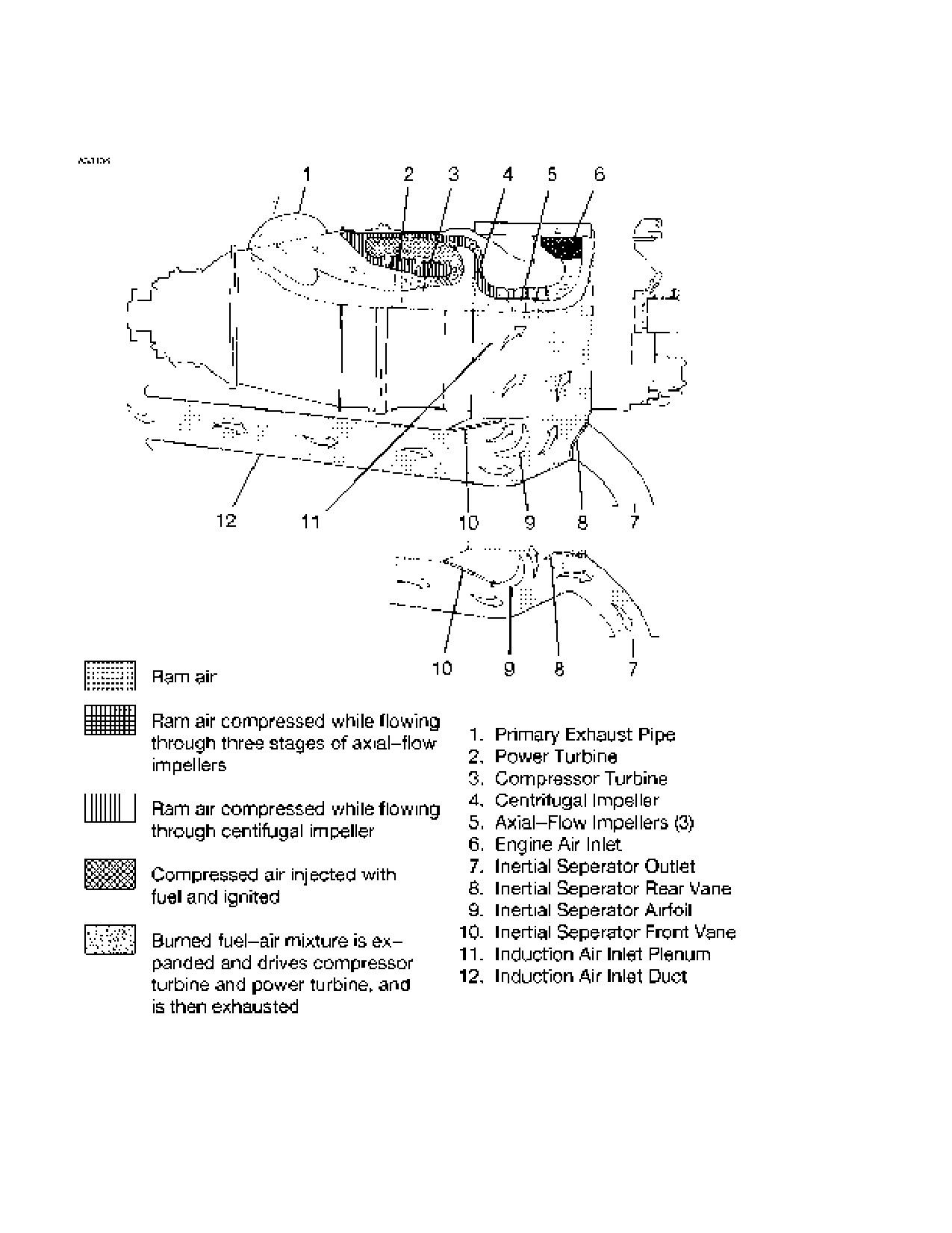
AIR INDUCTION SYSTEM
The engine air inlet is located at the front of the engine nacelle to the
left of the propeller spinner. Ram air entering the inlet flows through
ducts and an inertial separator system and then enters the engine
through a circular plenum chamber where it is directed to the
compressor by guide vanes. The compressor air inlet incorporates a
screen which will prevent entry of large articles, but does not filter the
inlet air.
7-62
U.S.
208BPHCUS-00
CESSNA
SECTION 7
MODEL 208B 867 SHP AIRPLANE AND SYSTEMS DESCRIPTION
GARMIN G1000
INERTIAL SEPARATOR SYSTEM
An inertial separator system in the engine air inlet duct prevents
moisture particles from entering the compressor air inlet plenum when
in bypass mode. The inertial separator consists of two movable vanes
and a fixed airfoil which, during normal operation, route the inlet air
through a gentle turn into the compressor air inlet plenum. When
separation of moisture particles is desired, the vanes are positioned so
that the inlet air is forced to execute a sharp turn in order to enter the
inlet plenum. This sharp turn causes any moisture particles to separate
from the inlet air and discharge overboard through the inertial separator
outlet in the left side of the cowling.
Inertial separator operation is controlled by a T-handle located on the
lower instrument panel. The T-handle is labeled BYPASS-PULL,
NORMAL-PUSH. The inertial separator control should be moved to the
BYPASS position prior to running the engine during ground or flight
operation in visible moisture (clouds, rain, snow, ice crystals) with an
OAT of 5°C (41°F) or less. It may also be used for ground operations or
takeoffs from dusty, sandy field conditions to minimize ingestion of
foreign particles into the compressor. The NORMAL position is used for
all other operations.
The T-handle locks in the NORMAL position by rotating the handle
clockwise 1/4 turn to its vertical position. To unlock, push forward
slightly and rotate the handle 90° counterclockwise. The handle can
then be pulled into the BYPASS position. Once moved to the BYPASS
position, air loads on the movable vanes hold them in this position.
CAUTION
Do not return the INERTIAL SEPARATOR to NORMAL
until after engine shutdown and inspection if icing
conditions are encountered.
NOTE
When moving the inertial separator control from BYPASS to
NORMAL position during flight, reduction of engine power
will reduce the control forces.
(Continued Next Page)
208BPHCUS-00
U.S.
7-63
SECTION 7
CESSNA
AIRPLANE AND SYSTEMS DESCRIPTION MODEL 208B 867 SHP
GARMIN G1000
ENGINE AIR FLOW
NOTE
The above view shows inertial separator in NORMAL position.
Auxiliary view shows inertial separator in BYPASS position.
Figure 7-9
7-64
U.S.
208BPHCUS-00
CESSNA
SECTION 7
MODEL 208B 867 SHP AIRPLANE AND SYSTEMS DESCRIPTION
GARMIN G1000
EXHAUST SYSTEM
The exhaust system consists of a primary exhaust pipe attached to the
right side of the engine just aft of the propeller reduction gearbox. A
secondary exhaust duct, fitted over the end of the primary exhaust pipe
carries the exhaust gases away from the cowling and into the
slipstream. The juncture of the primary exhaust pipe and secondary
exhaust duct is located directly behind the oil cooler. Since the
secondary exhaust duct is of larger diameter than the primary exhaust
pipe, a venturi effect is produced by the flow of exhaust. This venturi
effect creates a suction behind the oil cooler which augments the flow
of cooling air through the cooler. This additional airflow improves oil
cooling during ground operation of the engine.
ENGINE FUEL SYSTEM
The engine fuel system consists of an oil-to-fuel heater, an engine-
driven fuel pump, a fuel control unit, a flow divider and dump valve, a
dual fuel manifold with 14 simplex nozzles, and two fuel drain lines. The
system provides fuel flow to satisfy the speed and power demands of
the engine.
Fuel from the airplane reservoir is supplied to the oil-to-fuel heater
which utilizes heat from the engine lubricating oil system to preheat the
fuel in the fuel system. A fuel temperature-sensing oil bypass valve
regulates the fuel temperature by either allowing oil to flow through the
heater circuit or bypass it to the engine oil tank.
Fuel from the oil-to-fuel heater then enters the engine-driven fuel pump
chamber through a 74-micron inlet screen. The inlet screen is spring-
loaded and should it become blocked, the increase in differential
pressure will overcome the spring and allow unfiltered fuel to flow into
the pump chamber. The pump increases the fuel pressure and delivers
it to the fuel control unit via a 10-micron filter in the pump outlet. A
bypass valve and cored passages in the pump body enables unfiltered
high pressure fuel to flow to the fuel control unit in the event the outlet
filter becomes blocked.
(Continued Next Page)
208BPHCUS-00
U.S.
7-65
SECTION 7
CESSNA
AIRPLANE AND SYSTEMS DESCRIPTION MODEL 208B 867 SHP
GARMIN G1000
ENGINE FUEL SYSTEM (Continued)
The fuel control unit consists of a fuel metering section, a temperature
compensating section, and a gas generator (Ng) pneumatic governor.
The fuel control unit determines the proper fuel schedule to provide the
power required as established by the power lever input. This is
accomplished by controlling the speed of the compressor turbine. The
temperature compensating section alters the acceleration fuel schedule
to compensate for fuel density differences at different fuel
temperatures, especially during engine start. The power turbine
governor, located in the propeller governor housing, provides power
turbine overspeed protection in the event of propeller governor failure.
This is accomplished by limiting fuel to the gas generator. During
reverse thrust operation, maximum power turbine speed is controlled
by the power turbine governor. The temperature compensator alters the
acceleration fuel schedule of the fuel control unit to compensate for
variations in compressor inlet air temperature. Engine characteristics
vary with changes in inlet air temperature, and the acceleration fuel
schedule must, in turn, be altered to prevent compressor stall and/or
excessive turbine temperatures.
The flow divider schedules the metered fuel, from the fuel control unit,
between the primary and secondary fuel manifolds. The fuel manifold
and nozzle assemblies supply fuel to the combustion chamber through
10 primary and 4 secondary fuel nozzles, with the secondary nozzles
cutting in above a preset value. All nozzles are operative at idle and
above.
When the fuel cutoff valve in the fuel control unit closes during engine
shutdown, both primary and secondary manifolds are connected to a
dump valve port and residual fuel in the manifolds is allowed to drain
into the fuel can attached to the firewall where it can be drained daily.
COOLING SYSTEM
No external cooling provisions are provided for the PT6A-140 engine in
this installation. However, the engine incorporates an extensive internal
air system which provides for bearing compartment sealing and for
compressor and power turbine disk cooling. For additional information
on internal engine air systems, refer to the engine maintenance manual
for the airplane.
7-66
U.S.
208BPHCUS-00
CESSNA
SECTION 7
MODEL 208B 867 SHP AIRPLANE AND SYSTEMS DESCRIPTION
GARMIN G1000
STARTING SYSTEM
The starting system consists of a starter-generator, a starter switch,
and an amber STARTER ON annunciator. The starter-generator
functions as a motor for engine starting and will motor the gas
generator section until a speed of 46% Ng is reached, at which time, the
start cycle will automatically be terminated by a speed sensing switch
located in the starter-generator. The starter-generator is controlled by a
three-positioned starter switch located on the left sidewall switch and
circuit breaker panel. The switch has OFF, START, and MOTOR
positions. The OFF position deenergizes the ignition and starter circuits
and is the normal position at all times except during engine start. The
START position of the switch energizes the starter-generator which
rotates the gas generator portion of the engine for starting. Also, the
START position energizes the ignition system, provided the ignition
switch is in the NORMAL position. When the engine has started, the
starter switch must be manually placed in the OFF position to de-
energize the ignition system and activate the generator system. The
MOTOR position of the switch motors the engine without having the
ignition circuit energized and is used for motoring the engine when an
engine start is not desired. This can be used for clearing fuel from the
engine, washing the engine compressor, etc. The MOTOR position is
spring-loaded to the OFF position. Also, an interlock between the
MOTOR position of the starter switch and the ignition switch prevents
the starter from motoring unless the ignition switch is in the NORMAL
position. This prevents unintentional motoring of the engine with the
ignition on. Starter contactor operation is indicated by an amber
STARTER ON annunciator.
ENGINE ACCESSORIES
All engine-driven accessories, with the exception of the propeller
tachometer-generator and the propeller governors, are mounted on the
accessory gearbox located at the rear of the engine. These
accessories are driven from the compressor turbine by a coupling shaft
which extends the drive through a conical tube in the oil tank center
section.
208BPHCUS-00
U.S.
7-67
SECTION 7
CESSNA
AIRPLANE AND SYSTEMS DESCRIPTION MODEL 208B 867 SHP
GARMIN G1000
OIL PUMP
Pressure oil is circulated from the integral oil tank through the engine
lubrication system by a self-contained, gear-type pressure pump
located in the lowest part of the oil tank. The oil pump is contained in a
cast housing which is bolted to the front face of the accessory
diaphram, and is driven by the accessory gear shaft. The oil pump body
incorporates a circular mounting boss to accommodate a check valve,
located in the end of the filter housing. A second mounting boss on the
pump accommodates a pressure relief valve.
FUEL PUMP
The engine-driven pump is mounted on the accessory gearbox at the 2
o’clock position. The pump is driven through a gear shaft and splined
coupling. The coupling splines are lubricated by oil mist from the
auxiliary gearbox through a hole in the gear shaft. Another splined
coupling shaft extends the drive to the fuel control unit which is bolted
to the rear face of the pump. Fuel from the oil-to-fuel heater enters the
fuel pump through a 74-micron inlet screen. Then, fuel enters the pump
gear chamber, is boosted to high pressure, and delivered to the fuel
control unit through a 10-micron pump outlet filter. A bypass valve and
cored passages in the pump casing enable unfiltered high pressure fuel
to flow from the pump gears to the fuel control unit should the outlet
filter become blocked. An internal passage originating at the mating
face with the fuel control unit returns bypass fuel from the fuel control
unit to the pump inlet downstream of the inlet screen. A pressure
regulating valve in this line serves to pressurize the pump gear
bushings.
Ng TACHOMETER-GENERATOR
The Ng tachometer-generator produces an electric current which is
used in conjunction with the gas generator% RPM indicator to indicate
gas generator RPM. The Ng tachometer-generator drive and mount
pad is located at the 5 o’clock position on the accessory gearbox and is
driven from the internal scavenger pump.
7-68
U.S.
208BPHCUS-00
CESSNA
SECTION 7
MODEL 208B 867 SHP AIRPLANE AND SYSTEMS DESCRIPTION
GARMIN G1000
PROPELLER TACHOMETER-GENERATOR
The propeller tachometer-generator produces an electric signal which
is used in conjunction with the propeller RPM indicator. The propeller
tachometer- generator drive and mount pad is located on the right side
of the reduction gearbox case and rotates clockwise with a drive ratio of
0.1273:1.
TORQUEMETER
The torquemeter is a hydro-mechanical torque measuring device
located inside the first stage reduction gear housing to provide an
accurate indication of engine power output. The difference between the
torquemeter pressure and the reduction gearbox internal pressure
accurately indicates the torque being produced. The two pressures are
internally routed to bosses located on the top of the reduction gearbox
front case and to a pressure transducer which is electrically connected
to the G1000 which indicates the correct torque. For standby indication,
the pressures are routed to bosses on the top of the reduction
gearcase front case and plumbed to the standby torque indicator.
STARTER-GENERATOR
The starter-generator is mounted on the top of the accessory case at
the rear of the engine. The starter-generator is a 28-volt, 200-amp
engine-driven unit that functions as a motor for engine starting and,
after engine start, as a generator for the airplane electrical system.
When operating as a starter, a speed sensing switch in the
starter-generator will automatically shut down the starter, thereby
providing overspeed protection and automatic shutoff. The
starter-generator is air cooled by an integral fan, ram air ducted from
the front of the engine cowling and on airplanes equipped with the 300
amp starter generator, ram air is also supplied from a NACA scoop
located on the nosewheel fairing.
208BPHCUS-00
U.S.
7-69
SECTION 7
CESSNA
AIRPLANE AND SYSTEMS DESCRIPTION MODEL 208B 867 SHP
GARMIN G1000
INTERSTAGE TURBINE TEMPERATURE SENSING
SYSTEM
The interturbine temperature sensing system is designed to provide the
operator with an accurate indication of engine operating temperatures
taken between the compressor and power turbines. The system
consists of twin leads, two bus bars, and eight individual
chromel-alumel thermocouple probes connected in parallel. Each
probe protrudes through a threaded boss on the power turbine stator
housing into an area adjacent to the leading edge of the power turbine
vanes. The probe is secured to the boss by means of a floating,
threaded fitting which is part of the thermocouple probe assembly.
Shielded leads connect each bus bar assembly to a terminal block
which provides a connecting point for external leads to the ITT indicator
in the airplane cabin.
PROPELLER GOVERNOR
The propeller governor is located in the 12 o’clock position on the front
case of the reduction gearbox. Under normal conditions, the governor
acts as a constant speed unit, maintaining the propeller speed selected
by the pilot by varying the propeller blade pitch to match the load to the
engine torque. The propeller governor also has a power turbine
governor section built into the unit. Its function is to protect the engine
against a possible power turbine overspeed in the event of a propeller
governor failure. If such an overspeed should occur, a governing orifice
in the propeller governor is opened by flyweight action to bleed off
compressor discharge pressure through the governor and computing
section of the fuel control unit. When this occurs, compressor discharge
pressure, acting on the fuel control unit governor bellows, decreases
and moves the metering valve in a closing direction, thus reducing fuel
flow to the flow divider.
7-70
U.S.
208BPHCUS-00
CESSNA
SECTION 7
MODEL 208B 867 SHP AIRPLANE AND SYSTEMS DESCRIPTION
GARMIN G1000
TORQUE LIMITER
The torque limiter installed on the engine is a mechanical back-up unit
which prevents unintentional engine overtorques. On the PT6A-140
engine it limits the maximum torque value to 2500 FT-LB regardless of
propeller RPM.
The backup unit incorporates an oil bellows which senses torquemeter
oil pressure and is linked to a Py bleed orifice. Oil from the torquemeter
chamber passes through a restrictor before entering the bellows. The
restrictor dampens torque pressure fluctuation and prevents damage to
the bellows assembly. When torque pressure reaches 2500 FT-LB, the
bellows expands and compresses the spring.
Bimetallic disks are mounted on the spring to compensate for variation
of spring tension caused by change in ambient temperature.
The flapper valve then moves to allow Py air pressure from the fuel
control unit to vent to the atmosphere and therefore limit the fuel supply
to the engine reducing the engine speed and subsequently reducing
torque.
CAUTION
The pilot is always responsible for operating the engine
torque within limits and not depend on the mechanical
torque limiter.
208BPHCUS-00
U.S.
7-71
SECTION 7
CESSNA
AIRPLANE AND SYSTEMS DESCRIPTION MODEL 208B 867 SHP
GARMIN G1000
PROPELLER OVERSPEED GOVERNOR
This propeller overspeed governor is located at the 10 o’clock position
on the front case of the reduction gearbox. The governor acts as a
safeguard against propeller overspeed should the primary propeller
governor fail. The propeller overspeed governor regulates the flow of oil
to the propeller pitch-change mechanism by means of a flyweight and
speeder spring arrangement similar to the primary propeller governor.
Because it has no mechanical controls, the overspeed governor is
equipped with a test solenoid that resets the governor below its normal
overspeed setting for ground test. The OVERSPEED GOVERNOR
PUSH TO TEST Switch is located on the left side of the instrument
panel. For a discussion of this switch, refer to the paragraph titled
Propellers in this section.
ENGINE FIRE DETECTION SYSTEM
The engine fire detection system consists of a heat sensor in the
engine compartment, a red ENGINE FIRE annunciator located on the
PFD, and a warning horn above the pilot. The heat sensor consists of
three flexible closed loops. When high engine compartment
temperatures are experienced, the heat causes a change in resistance
in the closed loops. This change in resistance is sensed by a control
box, located on the aft side of the firewall, which will illuminate the red
ENGINE FIRE annunciator and trigger the audible warning horn. Fire
warning is initiated when temperatures in the engine compartment
exceed 425ºF (218ºC) on the first section (firewall), 625ºF (329ºC) on
the second section (around the exhaust), or 450ºF (232ºC) on the third
section (rear engine compartment).
A test switch, labeled TEST SWITCH, FIRE DETECT - UP, is located
on the lower left corner of the instrument panel. When this switch is
placed in the UP position, the red ENGINE FIRE annunciator will
illuminate on the CAS system and the warning horn will sound
indicating that the fire warning circuitry is operational. The system is
protected by a pull-off type circuit breaker, labeled FIRE DET, on the left
sidewall switch and circuit breaker panel.
7-72
U.S.
208BPHCUS-00
CESSNA
SECTION 7
MODEL 208B 867 SHP AIRPLANE AND SYSTEMS DESCRIPTION
GARMIN G1000
ENGINE GEAR REDUCTION SYSTEM
The reduction gear and propeller shaft, located in the front of the
engine, are housed in two magnesium alloy castings which are bolted
together at the exhaust outlet. The gearbox contains a two-stage
planetary gear train, three accessory drives, and propeller shaft. The
first-stage reduction gear is contained in the rear case, while the
second-stage reduction gear, accessory drives, and propeller shaft are
contained in the front case. Torque from the power turbine is
transmitted to the first-stage reduction gear, from there to the second
stage reduction gear, and then to the propeller shaft. The reduction
ratio is from a maximum power turbine speed of 33,000 RPM down to a
propeller speed of 1900 RPM.
The accessories, located on the front case of the reduction gearbox,
are driven by a bevel gear mounted at the rear of the propeller shaft
thrust bearing assembly. Drive shafts from the bevel drive gear transmit
rotational power to the three pads which are located at the 12, 3 and 9
o'clock positions. Propeller thrust loads are absorbed by a flanged ball
bearing assembly located on the front face of the reduction gearbox
center bore. The bevel drive gear adjusting spacer, thrust bearing, and
seal runner are stacked and secured to the propeller shaft by a key
washer and spanner nut. A thrust bearing cover assembly is secured
by bolts at the front flange of the reduction gearbox front case.
208BPHCUS-00
U.S.
7-73
SECTION 7
CESSNA
AIRPLANE AND SYSTEMS DESCRIPTION MODEL 208B 867 SHP
GARMIN G1000
CHIP DETECTORS
Two chip detectors are installed on the engine, one on the underside of
the reduction gearbox case and one on the underside of the accessory
gearbox case. The chip detectors are installed to trigger an amber
CHIP DETECT annunciations anytime metal chips are present in one
or both of the chip detectors. Illumination of the amber CHIP DETECT
annunciator indicates the need for engine inspection for abnormal
wear. The amber CHIP DETECT annunciation will also be shown if
either chip detectors electrical connector has come loose. The engine
oil must be drained prior to removing either of the chip detector
sensors. Refer to the 208 Maintenance Manual, for more information
on inspection and removal of the engine chip detectors.
OIL BREATHER DRAIN CAN
Model 208 airplanes have an oil breather drain can mounted on the
right lower engine mount truss. This can collects any engine oil
discharge coming from the accessory pads for the alternator drive
pulley, starter/generator, air conditioner compressor (if installed), and
the propeller shaft seal. This can should be drained after every flight. A
drain valve on the bottom right side of the engine cowling enables the
pilot to drain the contents of the oil breather drain can into a suitable
container. The allowable quantity of oil discharge per hour of engine
operation is 14 cc for airplanes with air conditioning and 11 cc for
airplanes without air conditioning. If the quantity of oil drained from the
can is greater than specified, the source of the leakage should be
identified and corrected prior to further flight.
7-74
U.S.
208BPHCUS-00
CESSNA
SECTION 7
MODEL 208B 867 SHP AIRPLANE AND SYSTEMS DESCRIPTION
GARMIN G1000
PROPELLER
The airplane is equipped standard with a Hartzell aluminum material,
three-bladed propeller. The propeller is constant-speed, full-feathering,
reversible, single-acting, governor-regulated propeller. A setting
introduced into the governor with the PROP RPM lever establishes the
propeller speed. The propeller utilizes oil pressure which opposes the
force of springs and counter-weights to obtain correct pitch for the
engine load. Oil pressure from the propeller governor drives the blades
toward low pitch (increases RPM) while the springs and counterweights
drive the blades toward high pitch (decreasing RPM). The source of oil
pressure for propeller operation is furnished by the engine oil system,
boosted in pressure by the governor gear pump, and supplied to the
propeller hub through the propeller flange.
To feather the propeller blades, the PROP RPM lever on the control
pedestal is placed in the FEATHER position; counterweights and spring
tension will continue to twist the propeller blades through high pitch and
into the streamlined or feathered position. Unfeathering the propeller is
accomplished by positioning the PROP RPM lever forward of the
feather gate. The unfeathering system uses engine oil pressure to force
the propeller out of feather.
Reversed propeller pitch is available for decreasing ground roll during
landing. To accomplish reverse pitch, the power lever is retarded
beyond IDLE and well into the BETA range. Maximum reverse power is
accomplished by retarding the power lever to the MAX REVERSE
position which increases power output from the gas generator and
positions the propeller blades at full reverse pitch. An externally
grooved feedback ring is provided with the propeller.
Motion of the feedback ring is proportional to propeller blade angle, and
is picked up by a carbon block running in the feedback ring. The
relationship between the axial position of the feedback ring and the
propeller blade angle is used to maintain control of blade angle from
idle to full reverse.
CAUTION
The propeller reversing linkage can be damaged if the
power lever is moved aft of the idle position when the
propeller is feathered.
208BPHCUS-00
U.S.
7-75
SECTION 7
CESSNA
AIRPLANE AND SYSTEMS DESCRIPTION MODEL 208B 867 SHP
GARMIN G1000
PROPELLER (Continued)
OVERSPEED GOVERNOR TEST SWITCH
An overspeed governor test switch is located on the left side of the
instrument panel. The switch is the push-to-test type and is used to test
the propeller overspeed governor during engine run-up. The switch,
when depressed, actuates a solenoid on the propeller overspeed
governor which restricts propeller RPM when the power lever is
advanced. To check for proper operation of the overspeed governor,
during engine run-up, depress the press-to-test switch and advance the
power lever until propeller RPM stabilizes; propeller RPM should not
exceed 1750 +/- 60 RPM.
FUEL SYSTEM
The airplane fuel system (see Fuel System figure) consists of two
vented, integral fuel tanks with shutoff valves, a fuel selectors off
warning system, a fuel reservoir, an ejector fuel pump, an electric
auxiliary boost pump, a reservoir manifold assembly, a firewall shutoff
valve, a fuel filter, an oil-to-fuel heater, an engine-driven fuel pump, a
fuel control unit, a flow divider, dual manifolds, and 14 fuel nozzle
assemblies. An ecology tank is also provided to collect unused fuel
from the fuel manifold during engine shutdown. This unused fuel is
returned to the engine through an ejector pump during the next engine
start. Refer to the Fuel Quantity Data Chart for information pertaining to
this system.
WARNING
Unusable fuel levels for this airplane were
determined in accordance with Federal Aviation
Regulations. Failure to operate the airplane in
compliance with the fuel limitations specified in
Section 2 may further reduce the amount of fuel
available in flight.
Fuel flows from the tanks through the two fuel tank shutoff valves at
each tanks. The fuel tank shutoff valves are mechanically controlled by
two fuel selectors, labeled LEFT, ON and OFF, located on the overhead
panel. By manipulating the fuel selectors, the pilot can select either left
or right fuel tanks or both at the same time. Normal operation is with
both tanks on. Fuel flows by gravity from the shutoff valves in each tank
to the fuel reservoir.
(Continued Next Page)
7-76
U.S.
208BPHCUS-01
CESSNA
SECTION 7
MODEL 208B 867 SHP AIRPLANE AND SYSTEMS DESCRIPTION
GARMIN G1000
FUEL SYSTEM (Continued)
The reservoir is located at the low point in the fuel system which
maintains a head of fuel around the ejector boost pump and auxiliary
boost pump which are contained within the reservoir. This head of fuel
prevents pump cavitation in low-fuel quantity situations, especially
during in-flight maneuvering. Fuel in the reservoir is pumped by the
ejector boost pump or by the electric auxiliary boost pump to the
reservoir manifold assembly. The ejector boost pump, which is driven
by motive fuel flow from the fuel control unit, normally provides fuel flow
when the engine is operating. In the event of failure of the ejector boost
pump, the electric boost pump will automatically turn on, thereby
supplying fuel flow to the engine. The auxiliary boost pump is also used
to supply fuel flow during starting. Fuel in the reservoir manifold then
flows through a fuel/oil shutoff valve located on the aft side of the
firewall. This shutoff valve enables the pilot to cut off all fuel to the
engine.
After passing through the shutoff valve, fuel is routed through a fuel
filter located on the right side of the engine. The fuel filter incorporates
a bypass feature which allows fuel to bypass the filter in the event the
filter becomes blocked with foreign material. Fuel from the filter is then
routed through the oil-to-fuel heater to the engine-driven fuel pump
where fuel is delivered under pressure to the fuel control unit. The fuel
control unit meters the fuel and directs it to the flow divider which
distributes the fuel to dual manifolds and 14 fuel nozzles located in the
combustion chamber. For additional details concerning the flow of fuel
at the engine, refer to the Engine Fuel System paragraph in this
section.
Fuel rejected by the engine during shutdown drains into the ecology
tank located on the front left side of the firewall. This unused fuel is then
drawn back into the fuel system through an ejector pump that uses flow
from the motive flow line and when the motive flow shutoff valve is
reenergized.
Fuel system venting is essential to system operation. Complete
blockage of the vent system will result in decreased fuel flow and
eventual engine stoppage. Venting is accomplished by check valve
equipped vent lines, one from each fuel tank, which protrude from the
trailing edge of the wing at the wing tips. also the fuel reservoir is
vented to both wing tanks.
208BPHCUS-01
U.S.
7-77

SECTION 7
CESSNA
AIRPLANE AND SYSTEMS DESCRIPTION MODEL 208B 867 SHP
GARMIN G1000
FUEL SYSTEM
Figure 7-10*
7-78
U.S.
208BPHCUS-01
CESSNA
SECTION 7
MODEL 208B 867 SHP AIRPLANE AND SYSTEMS DESCRIPTION
GARMIN G1000
FUEL SYSTEM (Continued)
FUEL QUANTITY DATA
FUEL LEVEL
TOTAL
UNITS OF
(QUANTITY EACH TOTAL
TOTAL
USABLE ALL
MEASURE
TANK)
FUEL UNUSABLE
FLT
CONDITIONS
FULL
(OUTBOARD
FILLERS)
POUNDS
1124.25
2272
24.1
2246.5
GALLONS
(U.S.)
167.8
339.1
3.6
335.3
NOTE
Pounds are based on a fuel specific weight of 6.7 pounds
per U.S. gallon.
WARNING
To achieve full capacity, fill fuel tank to the top of
the fuel filler neck. Filling fuel tanks to the bottom
of the fuel filler collar (level with the flapper valve)
allows space for thermal expansion and results in a
decrease in fuel capacity of four gallons per side
(eight gallons total).
Figure 7-11
208BPHCUS-00
U.S.
7-79
SECTION 7
CESSNA
AIRPLANE AND SYSTEMS DESCRIPTION MODEL 208B 867 SHP
GARMIN G1000
FUEL SYSTEM (Continued)
FIREWALL FUEL SHUTOFF VALVE
A firewall fuel shutoff valve, located on the aft side of the firewall,
enables the pilot to shut off all fuel flow from the fuel reservoir to the
engine. The shutoff valve is controlled by a red push-pull knob labeled
FUEL/OIL SHUTOFF located on the right side of the control pedestal.
The push-pull knob has a press-to-release button in the center which
locks the knob in position when the button is released.
FUEL TANK SELECTORS
Two FUEL SELECTORS, one for each tank, are located on the
overhead console. The selectors, labeled LEFT, ON and OFF and
RIGHT, ON and OFF, mechanically control the position of the two fuel
tank shutoff valves at each wing tank. When a FUEL TANK SELECTOR
is in the OFF position, the shutoff valves in the tank are closed. When in
the ON position, both shutoff valves in the tank are open, allowing fuel
from that tank to flow to the reservoir. Normal fuel management is with
both FUEL TANK SELECTORS are in the ON position.
Before refueling, or when the airplane is parked on a slope, turn off one
of the FUEL TANK SELECTORS (if parked on a slope, turn high wing
tank off). This action prevents crossfeeding from the fuller or higher
tank and reduces any fuel seepage tendency from the wing tank vents.
7-80
U.S.
208BPHCUS-00
CESSNA
SECTION 7
MODEL 208B 867 SHP AIRPLANE AND SYSTEMS DESCRIPTION
GARMIN G1000
FUEL SYSTEM (Continued)
FUEL SELECTORS OFF WARNING SYSTEM
A fuel selectors off warning system is incorporated to alert the pilot if
one or both of the FUEL TANK SELECTORS are in the OFF position
inadvertently. The system included redundant warning horns, a red
FUEL SELECT OFF annunciation of the selected tank, actuation
switches, and miscellaneous electrical hardware. The dual aural
warning system is powered through the START CONT circuit breaker
with a non-pullable FUEL SEL WARN circuit breaker installed in series
to protect the integrity of the start system.
The warning system functions as follows:
1. If both the LEFT and RIGHT FUEL TANK SELECTORS are in
the OFF position (fuel tank shutoff valves are closed), the red
FUEL SELECT OFF annunciator illuminates and one of the fuel
selector off warning horns is activated;
2. During an engine start operation (STARTER switch in START or
MOTOR position) with either the left or right fuel tank selectors
in the OFF position, the red FUEL SELECT OFF annunciator
illuminates and both of the fuel select off warning horns are
activated;
3. With one fuel tank selector in the OFF position and fuel
remaining in the tank being used is less than approximately 25
gallons, the red FUEL SELECT OFF annunciator illuminates
and one of the fuel selector off warning horns is activated.
The warning system has the ability to annunciate which fuel selector is
selected off by displaying OFF next to the respective fuel quantity
indicator on the EIS. There is no annunciation when the fuel selector is
turned ON.
If the FUEL SEL WARN circuit breaker has popped or the START
CONT circuit breaker has been pulled
(possible for ground
maintenance), the red FUEL SELECT OFF annunciator will be
illuminated even with both fuel tank selectors ON. This is a warning to
the pilot that the fuel selector warning system has been deactivated.
A test switch, labeled TEST SWITCH, FUEL SELECT OFF - DN, is
located on the lower left corner of the instrument panel. When this
switch is placed in the DOWN position, the two warning horns will
sound simultaneously indicating that the fuel selector warning horns
are operational.
208BPHCUS-00
U.S.
7-81
SECTION 7
CESSNA
AIRPLANE AND SYSTEMS DESCRIPTION MODEL 208B 867 SHP
GARMIN G1000
FUEL SYSTEM (Continued)
FUEL BOOST PUMP SWITCH
An auxiliary boost pump switch, located on the left sidewall switch and
circuit breaker panel, is labeled FUEL BOOST and has OFF, NORM,
and ON positions. When the FUEL BOOST switch is in the OFF
position, the auxiliary boost pump is inoperative. When the FUEL
BOOST switch is in the NORM position, the auxiliary boost pump is
armed and will operate when fuel pressure in the fuel manifold
assembly drops below 2.5 psi. The NORM position is used for all
normal engine operation where main fuel flow is provided by the ejector
boost pump and the auxiliary boost pump is used as a standby. When
the FUEL BOOST switch is placed in the ON position, the auxiliary
boost pump will operate continuously and the motive flow pump will be
shut off. The ON position is used for engine start and any other time
that the auxiliary boost pump cycles on and off with the switch in the
NORM position due to low fuel pressure.
The high pressure motive flow shutoff valve needs to be closed (FUEL
BOOST switch ON) during engine starts so there is sufficient fuel
pressure delivered to the Fuel Control Unit to open the minimum
pressurizing valve to allow fuel flow to the fuel nozzles. The fuel boost
pump incorporates a timer so when the fuel boost pump switch is
moved from ON to NORM or OFF the pump will continue to run for a
short period of time. This is to avoid the motive flow shutoff valve from
opening and the pump switching off at the same time. This prevents
potential low fuel pressure to the engine causing the boost pump to
cycle back on.
NOTE
If the FUEL BOOST pump switch is not turned ON prior to
engine start, (motive flow shutoff valve not energized) there
will be insufficient fuel pressure to open the minimum
pressurizing valve and the engine will not start.
7-82
U.S.
208BPHCUS-00
CESSNA
SECTION 7
MODEL 208B 867 SHP AIRPLANE AND SYSTEMS DESCRIPTION
GARMIN G1000
FUEL SYSTEM (Continued)
FUEL FLOW INDICATION
A fuel flow indicator, located beneath the quantity indicators on both the
ENGINE and SYSTEM pages, indicates the fuel consumption of the
engine in pounds per hour based on Jet A fuel. The indicator measures
the flow of fuel downstream of the fuel control unit just before being
routed into the flow divider. The fuel flow indicator receives power from
a pull-off type circuit breaker labeled F FLOW NP & NG, on the left
sidewall switch and circuit breaker panel.
208BPHCUS-00
U.S.
7-83
SECTION 7
CESSNA
AIRPLANE AND SYSTEMS DESCRIPTION MODEL 208B 867 SHP
GARMIN G1000
FUEL QUANTITY INDICATIONS
Fuel quantity is measured by four fuel quantity transmitters (two in each
tank) and indicated in the EIS section on the MFD below the oil
temperature indicators. The FUEL QTY indicators utilize twin vertical
scales that show fuel quantity for both the L and R tanks in LBS from 0
to 1000 in 200 pound increments. The fuel quantity indicators, which
measure volume, are calibrated in pounds (based on the weight of Jet
A fuel on a standard day). An empty tank is indicated by a red line.
When an indicator shows an empty tank, approximately 2.8 gallons
remain in the tank as unusable fuel. The left and right fuel level senders
each receive power from a pull-off type circuit breaker. The breakers
are labeled LEFT FUEL QTY and RIGHT FUEL QTY, respectively, and
are located on the left sidewall switch and circuit breaker panel.
WARNING
Because of the relatively long fuel tanks, fuel
quantity indicator accuracy is affected by
uncoordinated flight or a sloping ramp if reading
the indicators while on the ground. Therefore, to
obtain accurate fuel quantity readings, verify that
the airplane is parked in a laterally level condition,
or if in flight, make sure the airplane is in a
coordinated and stabilized condition for at least 1
minute.
WING TANK FUEL LOW CAUTION ANNUNCIATORS
Two float sensors one for each wing tank will trigger the appropriate
amber L FUEL LOW or R FUEL LOW annunciation when the fuel in the
respective tank is 25 gallons (170 lbs) or less. When the fuel quantity in
each tank is less than 25 gallons (170 lbs), amber L-R FUEL LOW
annunciator will replace the previously displayed L or R FUEL LOW
annunciator.
7-84
U.S.
208BPHCUS-00
CESSNA
SECTION 7
MODEL 208B 867 SHP AIRPLANE AND SYSTEMS DESCRIPTION
GARMIN G1000
RESERVOIR FUEL LOW WARNING ANNUNCIATOR
A red RSVR FUEL LOW annunciator is located on the PFD, and will
come on when the level of fuel in the reservoir drops to approximately
one-half full. With the fuel reservoir full, there is adequate fuel for
approximately
3 minutes of maximum continuous power or
approximately 9 minutes at idle power.
FUEL PRESSURE LOW WARNING ANNUNCIATOR
An amber FUEL PRESS LOW annunciator is located on the PFD, and
will illuminate when fuel pressure drops below 2.5 psi.
FUEL BOOST PUMP ON ANNUNCIATOR
An amber FUEL BOOST ON annunciator is located on the PFD and will
come on when the electric boost pump is operating, such as when the
FUEL BOOST pump switch is placed in the ON position or when the
FUEL BOOST pump switch is in the NORM position and fuel pressure
drops below 2.5 psi.
208BPHCUS-00
U.S.
7-85
SECTION 7
CESSNA
AIRPLANE AND SYSTEMS DESCRIPTION MODEL 208B 867 SHP
GARMIN G1000
DRAIN VALVES
The fuel system is equipped with drain valves to provide a means for
the examination of fuel in the system for contamination and grade.
Drain valves are located on the lower surface of each wing at the
inboard end of the fuel tank, in fuel tank external sumps, on the left side
of the cargo pod for the reservoir tank, and on the underside of the fuel
filter. Outboard fuel tank drain valves and their use is recommended if
the airplane is parked with one wing low on a sloping ramp. The drain
valves for the wing tanks and their external sumps are tool-operated
poppet type and are flush-external mounted. The wing tank and
external sump drain valves are constructed so that the phillips
screwdriver on the fuel sampler which is provided can be utilized to
depress the valve and then twist to lock the drain valve in the open
position. The drain valve for the reservoir is controlled by a double-
button push-pull drain control knob. When pulled out, fuel from the
reservoir drains out the rear fuel drain pipe located adjacent to the drain
valve. The drain valve for the fuel filter consists of a drain pipe which
can be depressed upward to drain fuel from the filter. The fuel sampler
can be used in conjunction with these drain valves for fuel sampling
and purging of the fuel system. The fuel tanks should be filled after
each flight when practical to minimize condensation.
Before each flight of the day and after each refueling, use a clear
sampler and drain fuel from the inboard fuel tank sump, external sump
quick-drain valves, fuel reservoir quick-drain valve, and fuel filter quick-
drain valve to determine if contaminants are present, and that the
airplane has been fueled with the proper fuel. If the airplane is parked
with one wing low on a sloping ramp, draining of the outboard fuel tank
sump quick-drain valves is also recommended. If contamination is
detected, drain all fuel drain points again. Take repeated samples from
all fuel drain points until all contamination has been removed. If after
repeated sampling, evidence of contamination still exists, the fuel tanks
should be completely drained and the fuel system cleaned. Do not fly
the airplane with contaminated or unapproved fuel.
WARNING
JP-4 and other NAPHTHA based fuels can cause
severe skin and eye irritation.
7-86
U.S.
208BPHCUS-00
CESSNA
SECTION 7
MODEL 208B 867 SHP AIRPLANE AND SYSTEMS DESCRIPTION
GARMIN G1000
FUEL ECOLOGY TANK
A fuel ecology tank is supplied with the engine and is mounted on the
engine side of the firewall, capturing fuel drained from the fuel nozzle
manifolds at engine shutdown. When the engine is restarted, motive
flow fuel feeds an ejector pump in the ecology tank, which picks up the
discharged fuel and recirculates it back into the fuel system.
FUEL PUMP DRAIN RESERVOIR
To control expended lubricating oil from the engine fuel pump drive
coupling area and provide a way to determine if fuel is leaking past the
fuel pump seal, this airplanes is equipped with a drainable reservoir to
collect this allowable discharge of oil and any fuel seepage. The
reservoir is mounted on the front left side of the firewall. It should be
drained once a day or at an interval not to exceed six engine
shutdowns. A drain valve on the bottom side of the cowling enables the
pilot to drain the contents of the reservoir into a suitable container. A
quantity of up to 3 cc of oil and 20 cc of fuel discharge per hour of
engine operation is allowable. If the quantity of oil or fuel drained from
the reservoir is greater than specified, the source of leakage should be
identified and corrected prior to further flight.
208BPHCUS-00
U.S.
7-87
SECTION 7
CESSNA
AIRPLANE AND SYSTEMS DESCRIPTION MODEL 208B 867 SHP
GARMIN G1000
BRAKE SYSTEM
The airplane has a single-disc, hydraulically-actuated brake on each
main landing gear wheel. Each brake is connected, by a hydraulic line,
to a master cylinder attached to each of the pilot's rudder pedals. The
brakes are operated by applying pressure to the top of either the left
(pilot's) or right
(copilot's) set of rudder pedals, which are
interconnected. When the airplane is parked, both main wheel brakes
may be set by utilizing the parking brake which is operated by a handle
below to the right of the pilot’s control wheel. To apply the parking
brake, set the brakes with the rudder pedals and pull the handle aft. To
release the parking brake, push the handle fully in.
A brake fluid reservoir, located just forward of the firewall on the left
side of the engine compartment, provides additional brake fluid for the
brake master cylinders. The fluid in the reservoir should be checked for
proper level prior to each flight.
For maximum brake life, keep the brake system properly maintained.
Airplanes are equipped with metallic type brakes, and require a special
brake burn-in before delivery
(or after brake replacement). When
conditions permit, hard brake application is beneficial in that the
resulting higher brake temperatures tend to maintain proper brake
glazing and will prolong the expected brake life. Conversely, the
habitual use of light and conservative brake application is detrimental to
metallic brakes.
Some of the symptoms of impending brake failure are: gradual
decrease in braking action after brake application, noisy or dragging
brakes, soft or spongy pedals, and excessive travel and weak braking
action. If any of these symptoms appear, the brake system is in need of
immediate attention. If, during taxi or landing roll, braking action
decreases, let up on the pedals and then re-apply the brakes with
heavy pressure. If the brakes become spongy or pedal travel
increases, pumping the pedals should build braking pressure. If one
brake becomes weak or fails, use the other brake sparingly while using
opposite rudder, as required, to offset the good brake.
7-88
U.S.
208BPHCUS-00
CESSNA
SECTION 7
MODEL 208B 867 SHP AIRPLANE AND SYSTEMS DESCRIPTION
GARMIN G1000
ELECTRICAL SYSTEM
The airplane is equipped with a 28-volt, direct-current electrical system,
refer to Figure 7-12, Electrical System. The system uses a 24-volt
sealed lead acid battery; located on the front right side of the firewall,
as a source of electrical energy. A 200-amp engine-driven starter-
generator is used to maintain the battery's state of charge. Power is
supplied to most general electrical and all avionics circuits through two
general buses, two avionics buses, and a hot battery bus. The battery
bus is energized continuously for cabin/courtesy lights and functions
requiring power when the two general buses are off. The two general
buses are on anytime the BATTERY switch is turned ON. All DC buses
are on anytime the BATTERY switch and the two AVIONICS switches
are turned ON.
STANDBY ELECTRICAL SYSTEM
The standby electrical system serves as a power source in the event
the main generator system malfunctions in flight. The system includes
an alternator operated at a 75-amp capacity rating. The alternator is
belt-driven from an accessory pad on the rear of the engine. The
system also includes an alternator control unit located forward of the
circuit breaker panel, a standby alternator contactor assembly on the
left front side of the firewall and two switches on the left sidewall switch
panel, labeled STBY ALT PWR and AVIONICS STBY PWR.
Circuit protection and isolation is provided by two circuit breakers,
labeled STBY PWR, on the left sidewall circuit breaker panel. Field
excitation to the alternator control unit is supplied through diode logic
from a circuit breaker in the standby alternator relay assembly or from
the HOURMETER/ACU circuit breaker in the main power relay box.
Standby electrical system monitoring is provided by annunciators; white
STBY PWR ON annunciator and amber STBY PWR INOP annunciator.
Total amperage supplied from the standby electrical system can be
monitored on the EIS SYSTEMS DISPLAY. Additionally, an amber
ALTNR AMPS annunciator is provided if the standby alternator
amperage draw exceeds normal operating ranges.
208BPHCUS-00
U.S.
7-89
SECTION 7
CESSNA
AIRPLANE AND SYSTEMS DESCRIPTION MODEL 208B 867 SHP
GARMIN G1000
ELECTRICAL SYSTEM (Continued)
GENERATOR CONTROL UNIT
The generator control unit (GCU) is mounted inside the cabin on the left
forward fuselage sidewall. The unit provides the electrical control
functions necessary for the operation of the starter-generator. The GCU
provides for automatic starter cutoff when engine RPM is above 46%.
Below 46%, the starter-generator functions as a starter, and above
46%, the starter-generator functions as a generator when the
STARTER switch is OFF. The GCU provides voltage regulation plus
high voltage protection and reverse current protection. In the event of a
high-voltage or reverse current condition, the generator is automatically
disconnected from the buses. The generator contactor (controlled by
the GCU) connects the generator output to the airplane bus. If any
GCU function causes the generator contactor to de-energize, the
amber GENERATOR OFF annunciator will illuminate.
GROUND POWER MONITOR
The ground power monitor is located inside the electrical power control
assembly mounted on the left hand side of the firewall in the engine
compartment. This unit senses the voltage level applied to the external
power receptacle and will close the external power contactor when the
applied voltage is within the proper limits.
BATTERY SWITCH
The BATTERY switch is a two-position toggle-type switch, labeled
BATTERY, and is located on the left sidewall switch and circuit breaker
panel. The BATTERY switch is ON in the forward position and OFF in
the aft position. When the BATTERY switch is in the ON position,
battery power is supplied to the two general buses. The OFF position
removes power to all buses except the battery bus.
7-90
U.S.
208BPHCUS-00
CESSNA
SECTION 7
MODEL 208B 867 SHP AIRPLANE AND SYSTEMS DESCRIPTION
GARMIN G1000
ELECTRICAL SYSTEM (Continued)
STARTER SWITCH
The STARTER switch is a three-position toggle-type switch, labeled
STARTER, on the left sidewall switch and circuit breaker panel. The
switch has OFF, START, and MOTOR positions. For additional details
of the STARTER switch, refer to the starting system paragraph in this
section.
IGNITION SWITCH
The IGNITION switch is a two-position toggle-type switch, labeled
IGNITION, on the left sidewall switch and circuit breaker panel. The
switch has ON and NORMAL positions. For additional details of the
IGNITION switch, refer to the ignition system paragraph in this section.
GENERATOR SWITCH
The GENERATOR switch is a three-position toggle-type switch, labeled
GENERATOR, on the left sidewall switch and circuit breaker panel. The
switch has ON, RESET, and TRIP positions. With the switch in the ON
position, the GCU will automatically control the generator line contactor
for normal generator operation. The RESET and TRIP positions are
momentary positions and are spring-loaded to the ON position. If a
momentary fault should occur in the generating system (as evidenced
by the amber GENERATOR OFF annunciator, red VOLTAGE LOW
annunciator and/or red VOLTAGE HIGH annunciator), the
GENERATOR switch can be momentarily placed in the RESET position
to restore generator power. If erratic operation of the generating system
is observed, the system can be shutoff by momentarily placing the
GENERATOR switch to the TRIP position. After a suitable waiting
period, generator operation may be recycled by placing the
GENERATOR switch momentarily to RESET.
208BPHCUS-00
U.S.
7-91
SECTION 7
CESSNA
AIRPLANE AND SYSTEMS DESCRIPTION MODEL 208B 867 SHP
GARMIN G1000
ELECTRICAL SYSTEM (Continued)
STANDBY ALTERNATOR POWER SWITCH
The STBY ALT PWR switch is a two-position toggle-type switch,
labeled STBY ALT PWR. There is also an amber LED light located
above the switch that comes on when the BATTERY switch is in the
OFF position with STBY ALT PWR switch in the ON position. This is an
alert to the operator to help prevent accidental discharging of the
battery that can occur if the STBY ALT PWR switch is left ON after
shutdown.
AVIONICS POWER SWITCHES
Electrical power from the airplane power distribution bus to the avionics
buses, refer to Figure 7-12, Electrical System, is controlled by two
toggle-type switch/breakers located on the left sidewall switch and
circuit breaker panel. One switch controls power to the No. 1 avionics
bus while the other switch controls power to the No. 2 avionics bus. The
switches are labeled AVIONICS 1 and 2 and are ON in the forward
position and OFF in the aft position. The AVIONICS power switches
should be placed in the OFF position prior to turning the BATTERY
switch ON or OFF, or applying an external power source. The
AVIONICS No. 1 Switch must be ON prior to engine start to display EIS
information.
AVIONICS STANDBY POWER SWITCH
The AVIONICS STBY PWR switch is a guarded two-position switch/
breaker, labeled AVIONICS STBY PWR. The guard covering this
switch must be lifted in order to select the ON position. When switched
ON, the standby electrical system directly provides power to the AVN
BUS 1. When switched OFF, the standby electrical system may provide
extra power to the avionics buses via the main power distribution bus,
provided the STBY PWR circuit breakers on the electrical buses are not
pulled. When operating solely on standby power, both AVIONICS No. 1
and No. 2 power switches should be OFF to avoid feeding a possible
fault in the primary power system.
7-92
U.S.
208BPHCUS-00
CESSNA
SECTION 7
MODEL 208B 867 SHP AIRPLANE AND SYSTEMS DESCRIPTION
GARMIN G1000
ELECTRICAL SYSTEM (Continued)
AVIONICS BUS TIE SWITCH
The AVIONICS BUS TIE switch is a two-position guarded toggle-type
switch located on the left sidewall switch and circuit breaker panel. The
switch connects the AVN BUS 1 and AVN BUS 2 together in the event
of failure of either bus feeder circuit. Because power for each avionics
bus is supplied from a separate current limiter on the power distribution
bus, failure of a current limiter can cause failure of the affected bus.
Placing the AVIONICS BUS TIE switch to the ON position will restore
power to the failed bus. Operation without both bus feeder circuits may
require an avionics load reduction, depending on equipment installed.
208BPHCUS-00
U.S.
7-93

SECTION 7
CESSNA
AIRPLANE AND SYSTEMS DESCRIPTION MODEL 208B 867 SHP
GARMIN G1000
ELECTRICAL SYSTEM
Figure 7-12 (Sheet 1 of 3)
7-94
U.S.
208BPHCUS-00

CESSNA
SECTION 7
MODEL 208B 867 SHP AIRPLANE AND SYSTEMS DESCRIPTION
GARMIN G1000
ELECTRICAL SYSTEM
Figure 7-12 (Sheet 2 of 3)
208BPHCUS-00
U.S.
7-95

SECTION 7
CESSNA
AIRPLANE AND SYSTEMS DESCRIPTION MODEL 208B 867 SHP
GARMIN G1000
ELECTRICAL SYSTEM
Figure 7-12 (Sheet 3 of 3)
7-96
U.S.
208BPHCUS-00
CESSNA
SECTION 7
MODEL 208B 867 SHP AIRPLANE AND SYSTEMS DESCRIPTION
GARMIN G1000
ELECTRICAL SYSTEM (Continued)
EXTERNAL POWER SWITCH
The EXTERNAL POWER switch is a three-position guarded toggle-
type switch located on the left sidewall switch and circuit breaker panel.
The switch has OFF, STARTER, and BUS positions and is guarded in
the OFF position. When the switch is in the OFF position, battery power
is supplied to the main bus and to the starter-generator circuit, external
power cannot be applied to the main bus, and, with the generator
switch in the ON position, power is applied to the generator control
circuit. When the EXTERNAL POWER switch is in the STARTER
position, external power is applied to the starter circuit only and battery
power is supplied to the main bus. No generator power is available in
this position. When the EXTERNAL POWER switch is in the BUS
position, external power is applied to the main bus and no power is
available to the starter. The battery can be connected to the main bus
with external power connected to the airplane by placing the BATTERY
switch to the ON position. The battery charge must be monitored to
prevent a overcharge condition.
CIRCUIT BREAKERS
Most of the electrical circuits in the airplane are protected by pull-off
type circuit breakers mounted on the left sidewall switch and circuit
breaker panel. Should an overload occur in any circuit, the controlling
circuit breaker will trip, opening the circuit. After allowing the circuit
breaker to cool for approximately three minutes, it may be reset
(pushed in). If the breaker trips again, it should not be reset until
corrective action is taken.
WARNING
Make sure all circuit breakers are in before all
flights. Never operate with tripped circuit breakers
without a thorough knowledge of the
consequences.
208BPHCUS-00
U.S.
7-97
SECTION 7
CESSNA
AIRPLANE AND SYSTEMS DESCRIPTION MODEL 208B 867 SHP
GARMIN G1000
ELECTRICAL SYSTEM (Continued)
VOLTAGE AND AMPERAGE DISPLAY
The status of the electrical system can be monitored on the MFD (non-
reversionary mode). Battery current (BAT AMPS) and bus voltage
(BUS VOLTS) are displayed on the default EIS-ENGINE display page.
By pressing the ENGINE softkey and the SYSTEM softkey, the EIS
pages changes to the EIS-Systems display where generator current
(GEN AMPS), and bus voltage (BUS VOLTS) can be monitored
simultaneously. A negative display on BAT AMPS indicates battery
discharge, while a positive display indicates battery charging. A
negative display on BAT AMPS will be shown in amber to remind the
pilot to reduce electrical load, or increase Ng, to maintain battery
charge.
GROUND SERVICE PLUG RECEPTACLE
A ground service plug receptacle permits the use of an external power
source for cold weather starting and during lengthy maintenance work
on the electrical and avionics equipment. External power control
circuitry is provided to prevent the external power and the battery from
being connected together during starting. The external power
receptacle is installed on the left side of the engine compartment near
the firewall.
The ground service circuit incorporates polarity reversal and
overvoltage protection. Power from the external power source will flow
only if the ground service plug is correctly connected to the airplane. If
the plug is accidentally connected backwards or the ground service
voltage is too high, no power will flow to the electrical system, thereby
preventing any damage to electrical equipment.
7-98
U.S.
208BPHCUS-00
CESSNA
SECTION 7
MODEL 208B 867 SHP AIRPLANE AND SYSTEMS DESCRIPTION
GARMIN G1000
LIGHTING SYSTEMS
EXTERIOR LIGHTING
Exterior lighting consists of three navigation lights, two landing lights,
two taxi/recognition lights, two strobe lights, a flashing beacon, two
underwing courtesy lights and one wing inspection light. All exterior
lights are controlled by toggle switches located on the lighting control
panel on the left side of the instrument panel. The toggle switches are
ON in the up position and OFF in the down position. All exterior lights
are LED.
NAVIGATION LIGHTS
LED navigation lights are installed on the wing tips along with rear-
facing wing LED navigation lights that replace the traditional tailcone
white navigation light. The lights are protected by a pull-off type circuit
breaker, labeled NAV LIGHT, on the left sidewall switch and circuit
breaker panel.
LANDING LIGHTS
Two LED landing lights are installed on the airplane, one in each wing
leading edge mounted outboard of each taxi light. The lights provide
illumination forward and downward during takeoff and landing. The
lights are protected by two pull-off type circuit breakers, labeled LEFT
LDG LIGHT and RIGHT LDG LIGHT, on the left sidewall switch and
circuit breaker panel.
TAXI/RECOGNITION LIGHTS
Two LED taxi/recognition lights are mounted inboard of each landing
light in each wing leading edge. The lights are focused to provide
illumination of the area forward of the airplane during ground operation
and taxiing. The lights are also used to enhance visibility of the airplane
in the traffic pattern or enroute. The taxi/recognition lights are protected
by a pull-off type circuit breaker, labeled TAXI LIGHT, on the left
sidewall switch and circuit breaker panel.
208BPHCUS-00
U.S.
7-99
SECTION 7
CESSNA
AIRPLANE AND SYSTEMS DESCRIPTION MODEL 208B 867 SHP
GARMIN G1000
LIGHTING SYSTEMS (Continued)
EXTERIOR LIGHTING (Continued)
STROBE LIGHTS
A high intensity LED strobe light system is installed on the airplane. The
system includes two strobe lights located one on each wing tip. The
lights are used to enhance anti-collision protection for the airplane and
are required anti-collision lights for night operations. The strobe lights
are protected by a pull-off type circuit breaker, labeled STROBE LIGHT,
on the left sidewall switch and circuit breaker panel.
WARNING
Strobe lights should be turned off when taxiing.
Ground operation of the high intensity anti-
collision lights can be considerable annoyance to
ground personnel and other pilots. Do not operate
the anti-collision lights in conditions of fog, clouds,
or haze as the reflection of the light beam can
cause disorientation or vertigo.
FLASHING BEACON LIGHT
A red flashing LED beacon light is installed on the top of the vertical fin
as additional anti-collision protection in flight and for recognition during
ground operation. The light is visible through most angles. The flashing
beacon light is protected by a pull-off type circuit breaker, labeled
BEACON LIGHT, on the left sidewall switch and circuit breaker panel.
WARNING
The flashing beacon should not be used when
flying through clouds or overcast; the flashing light
reflected from water droplets or particles in the
atmosphere, particularly at night, can cause
disorientation or vertigo.
7-100
U.S.
208BPHCUS-00
CESSNA
SECTION 7
MODEL 208B 867 SHP AIRPLANE AND SYSTEMS DESCRIPTION
GARMIN G1000
LIGHTING SYSTEMS (Continued)
EXTERIOR LIGHTING (Continued)
WING INSPECTION LIGHT
One LED wing inspection light is installed in the left hand wing root
fairing. The light illuminates the left hand wing and left hand wing strut
for ice detection. The WING LIGHT switch is on the left hand switch
panel and is protected by a pull-type circuit breaker labeled WING ICE
DET LIGHT.
COURTESY LIGHTS
Two LED courtesy lights are installed, one under each wing. The lights
illuminate the area outside of the airplane adjacent to the crew entry
doors. The lights operate in conjunction with the cabin lights and are
controlled by the CABIN light switch as described in the cabin lights
paragraph in this section.
208BPHCUS-00
U.S.
7-101
SECTION 7
CESSNA
AIRPLANE AND SYSTEMS DESCRIPTION MODEL 208B 867 SHP
GARMIN G1000
LIGHTING SYSTEMS (Continued)
INTERIOR LIGHTING
Instrument and control panel lighting is provided by integral and flood
lights. Six lighting control knobs are grouped together on the lower part
of the instrument panel to the left of the control pedestal. These
controls vary the intensity of the lighting for the instrument panels,
pedestal, overhead panel, left sidewall panel, LED panels, Garmin
displays, and internally lit standby instruments. The following
paragraphs describe the function of these controls. The circuits for
these lights are protected by two pull-off type circuit breakers, labeled
AVN/LED/STBY LIGHTS and COCKPIT FLOOD LIGHTS, on the left
sidewall switch and circuit breaker panel. Other miscellaneous lighting
provided or available includes control wheel map LED lights, cabin
lights, LED passenger reading lights, and a no smoking/seat belt sign.
Discussion of these lights and their controls is also included in the
following paragraphs. Most interior lighting is LED.
GARMIN DISPLAYS, OPTIONAL ADF, AND HF DISPLAYS (if
installed)
The AVIONICS knob varies the intensity of the Garmin and optional
displays (if installed). Clockwise rotation of the knob increases display
brightness and counterclockwise rotation decreases brightness. The
displays cannot be dimmed to full dark. Rotating this knob
counterclockwise past the dimmest setting will place the displays in
photosensitive mode.
STANDBY INDICATOR CONTROL KNOB
The STANDBY IND knob varies the intensity of the Non-LED integral
lighting of the standby airspeed indicator, attitude indicator, altimeter,
torque indicator and magnetic compass. Clockwise rotation of the knob
increases light brightness and counterclockwise rotation decreases
brightness.
7-102
U.S.
208BPHCUS-00
CESSNA
SECTION 7
MODEL 208B 867 SHP AIRPLANE AND SYSTEMS DESCRIPTION
GARMIN G1000
LIGHTING SYSTEMS (Continued)
INTERIOR LIGHTING (Continued)
LED PANELS/ANNUN CONTROL KNOB
The LED PANELS/ANNUN knob varies the intensity of the backlit LED
panels. These panels are inscribed with labels for the switches,
controls, and circuit breakers mounted on the instrument panel.
Clockwise rotation of the knob increases panel brightness and
counterclockwise rotation decreases brightness.
CENTER FLOOD/MAP PANEL KNOB
The CENTER FLOOD knob varies the intensity of the light that
illuminates either pilot’s seat. Clockwise rotation of the knob increases
panel brightness and counterclockwise rotation decreases brightness.
LEFT FLOOD/MAP LIGHTING CONTROL KNOB
The LEFT FLOOD knob varies the brightness of the floodlight located
on the right aft side of the overhead panel. This floodlight may be used
to illuminate the pilot’s map or chart. Clockwise rotation of this control
knob increases lamp brightness while counterclockwise rotation
decreases brightness.
RIGHT FLOOD/MAP LIGHTING CONTROL KNOB
This RIGHT FLOOD knob varies the brightness of the floodlight located
on the left aft side of the overhead panel. This floodlight may be used to
illuminate the co-pilot’s map or chart. Clockwise rotation of this control
knob increases lamp brightness while counterclockwise rotation
decreases brightness.
CONTROL WHEEL MAPLIGHTS
A control wheel maplight is mounted on the bottom of each control
wheel. These lights illuminate the lower portion of the cabin in front of
the pilot and copilot, and are used for checking maps and other flight
data during night operations. Brightness of these lights is adjusted with
a rheostat control knob on the bottom of the control wheel. Rotating the
near side of the knob to the right increases light brightness and to the
left decreases brightness.
208BPHCUS-00
U.S.
7-103
SECTION 7
CESSNA
AIRPLANE AND SYSTEMS DESCRIPTION MODEL 208B 867 SHP
GARMIN G1000
LIGHTING SYSTEMS (Continued)
INTERIOR LIGHTING (Continued)
CABIN LIGHTS WITHOUT TIMER (208B Passenger)
The 208B passenger cabin light system without timer consists of four
LED cabin lights installed on the interior of the airplane and courtesy
lights under each wing to facilitate boarding or loading cargo during
night operations. Two lights are located above the center cabin area,
one above the aft cargo door, and one above the aft passenger door.
Controls for the lighting system consists of one 2-way toggle switch
labeled CABIN on the lighting control panel as well as a rocker switch
just forward of both the aft passenger and cargo doors. All three of
these switches will toggle all cabin lights on or off at any time
regardless of the other switch positions.
The circuit for the cabin lights is protected by a pull-off type circuit
breaker, labeled CABIN LTS, on the J-Box panel in the engine bay.
CABIN LIGHTS WITH TIMER (if installed)
The 208B cabin light system with timer consists of four LED cabin lights
installed on the interior of the airplane and courtesy lights under each
wing to facilitate boarding or loading cargo during night operations. Two
lights are located above the center cabin area, one above the aft cargo
door, and one above the aft passenger door.
Controls for the lighting system consists of one 3-way momentary
switch labeled CABIN on the lighting control panel as well as a rocker
switch just forward of both the aft passenger and cargo doors. The
passenger door toggle switch will control all lights except the cargo
door light, while the cargo door toggle switch will control only the cargo
door light. The 3-way momentary switch labeled CABIN on the lighting
control panel will control all lights regardless of the other switch
positions.
The timer circuitry includes a solid state timer that will turn off all lights
after 30 minutes automatically unless they are switched off manually.
The circuit for the cabin lights is protected by a “pull-off” type circuit
breaker, labeled CABIN LTS, on the J-Box panel in the engine bay.
7-104
U.S.
208BPHCUS-00
CESSNA
SECTION 7
MODEL 208B 867 SHP AIRPLANE AND SYSTEMS DESCRIPTION
GARMIN G1000
LIGHTING SYSTEMS (Continued)
INTERIOR LIGHTING (Continued)
CABIN LIGHTS WITH TIMER (Super CargoMaster)
The Super CargoMaster cabin light system consists of four LED cabin
lights installed on the interior of the airplane and courtesy lights under
each wing to facilitate boarding or loading cargo during night
operations. Two lights are located above the center cabin area, one
above the aft cargo door and one opposite the aft cargo door.
Controls for the lighting system consists of one 3-way momentary
switch labeled CABIN on the lighting control panel as well as a rocker
switch just forward of the cargo door.
PASSENGER READING LIGHTS (Passenger Version Only)
Passenger reading lights may be installed near each of the aft
passengers positions. The LED lights are located in
14 small
convenience panels above each seat. A pushbutton-type ON, OFF
switch, mounted in each panel, controls the lights. The lights can be
pivoted in their mounting sockets to provide the most comfortable angle
of illumination for the passenger.
NO SMOKE/SEAT BELT SIGN (Passenger Version Only)
A lighted warning sign may be installed in the airplane to facilitate
warning passengers of impending flight operations necessitating the
fastening of seat belts and/or the extinguishing of all smoking materials.
This installation consists of a small lighted panel mounted in the cabin
headliner immediately aft of the overhead console and two toggle-type
switches, labeled SEAT BELT and NO SMOKE, on the lighting control
panel. When these switches are placed in the ON position, the warning
signs illuminate, displaying the international graphic symbolism for
fasten seat belts and no smoking to the rear cabin passengers. The
circuit for the warning sign lights is protected by a pull-off type circuit
breaker, labeled SEAT BELT SIGN, on the left sidewall switch and
circuit breaker panel.
208BPHCUS-00
U.S.
7-105
SECTION 7
CESSNA
AIRPLANE AND SYSTEMS DESCRIPTION MODEL 208B 867 SHP
GARMIN G1000
CABIN HEATING, VENTILATING AND DEFROSTING
SYSTEM
The temperature and volume of airflow to the cabin is regulated by the
cabin heating, ventilating and defrosting system, refer to Figure 7- 13,
Cabin Heating, Ventilating and Defrosting System. In the heating
system, hot compressor outlet air is routed from the engine through a
flow control valve, then through a mixer/muffler where it is mixed with
cabin return air or warm air from the compressor bleed valve
(depending on the setting of the mixing air valve) to obtain the correct
air temperature before the air is routed to the cabin air distribution
system.
Controls are provided to direct the heated air to the forward and/or aft
portions of the cabin for heating and to the windshield for defrosting.
Ventilating air is obtained from an inlet on each side at the forward
fuselage and through two ram air inlets, one on each wing at the upper
end of the wing struts. The wing inlet ventilating air is routed through
the wing into a plenum chamber located in the center of the cabin top.
The plenum distributes the ventilating air to individual overhead outlets
near each seat position. Two electric blowers are available for the
overhead ventilating system. Refer to Section 9, Supplement 7, for
additional information on ventilating and Air Conditioning systems.
BLEED AIR HEAT SWITCH
A two-position toggle switch, labeled BLEED AIR HEAT, is located on
the CABIN HEAT switch and control panel. The switch controls the
operation of the bleed air flow control valve. The ON position of the
switch opens the flow control valve, allowing hot bleed air to flow to the
cabin heating system. The OFF position (down) closes the valve,
shutting off flow of hot bleed air to the heating system.
7-106
U.S.
208BPHCUS-00
CESSNA
SECTION 7
MODEL 208B 867 SHP AIRPLANE AND SYSTEMS DESCRIPTION
GARMIN G1000
CABIN HEATING, VENTILATING AND DEFROSTING
SYSTEM (Continued)
TEMPERATURE SELECTOR KNOB
A rotary temperature selector knob, labeled TEMP Control Knob, is
located on the CABIN HEAT switch and control panel. The selector
modulates the opening and closing action of the flow control valve to
control the amount and temperature of air flowing into the cabin.
Clockwise rotation of the TEMP Control Knob increases the mass flow
and temperature of the air.
NOTE
• If more cabin heat is needed while on the ground, move
the FUEL CONDITION lever to HIGH IDLE and/or select
the GRD position (pulled out) of the MIXING AIR control.
• Some hysteresis may be encountered when adjusting
bleed air temperature. The resulting amount and
temperature of bleed air may be different when
approaching a particular temperature selector knob
position from a clockwise versus a counterclockwise
direction. Best results can usually be obtained by turning
the temperature selector knob full clockwise and then
slowly turning it counterclockwise to decrease bleed
airflow to the desired amount.
A temperature sensor, located in the outlet duct from the mixer/muffler
operates in conjunction with the TEMP control knob. In the event of a
high temperature condition
(overheat) in the outlet duct, the
temperature sensor will be energized, closing the flow control valve and
thus shutting off the source of hot bleed air from the engine.
208BPHCUS-00
U.S.
7-107

SECTION 7
CESSNA
AIRPLANE AND SYSTEMS DESCRIPTION MODEL 208B 867 SHP
GARMIN G1000
CABIN HEATING, VENTILATING AND DEFROSTING
SYSTEM (CARGO VERSION)
Figure 7-13 (Sheet 1 of 2)
7-108
U.S.
208BPHCUS-00

CESSNA
SECTION 7
MODEL 208B 867 SHP AIRPLANE AND SYSTEMS DESCRIPTION
GARMIN G1000
CABIN HEATING, VENTILATING AND DEFROSTING
SYSTEM (PASSENGER VERSION)
Figure 7-13 (Sheet 2 of 2)
208BPHCUS-00
U.S.
7-109
SECTION 7
CESSNA
AIRPLANE AND SYSTEMS DESCRIPTION MODEL 208B 867 SHP
GARMIN G1000
CABIN HEATING, VENTILATING AND DEFROSTING
SYSTEM (Continued)
MIXING AIR PUSH-PULL CONTROL
A push-pull control, labeled MIXING AIR, GRD-PULL, FLT-PUSH, is
located on the CABIN HEAT switch and control panel. With the push-
pull control in the GRD position (pulled out), warm compressor bleed
valve air is mixed with hot compressor outlet air in the mixer/muffler.
This mode is used during ground operation when warm compressor
bleed valve air is available (at power setting below 92% Ng) and can be
used as additional bleed air heat to augment the hot compressor outlet
bleed air supply during periods of cold ambient temperature. With the
push-pull control in the FLT position (pushed in), cabin return air is
mixed with the hot compressor outlet air in the mixer/muffler. This
recirculation of cabin return air enables the heating system to maintain
the desired temperature for proper cabin heating. If desired, the FLT
position of the push-pull control can be used on the ground when
ambient temperatures are mild and maximum heating is not required.
In this mode, the excess warm compressor bleed valve air available at
power settings below 92% Ng is exhausted overboard from the mixing
air valve.
CAUTION
The MIXING AIR push-pull control should always be in
the FLT position (pushed in) when the airplane is in
flight. Cabin return air must be allowed to flow through
the mixing valve and blend with hot compressor outlet
air during high engine power operation in order to
maintain proper temperature in the cabin heat
distribution system. If the FLT position is not used
during flight, the system may overheat and cause an
automatic shutdown.
7-110
U.S.
208BPHCUS-00
CESSNA
SECTION 7
MODEL 208B 867 SHP AIRPLANE AND SYSTEMS DESCRIPTION
GARMIN G1000
CABIN HEATING, VENTILATING AND DEFROSTING
SYSTEM (Continued)
AFT/FORWARD CABIN PUSH-PULL CONTROL
A push-pull control, labeled AFT CABIN-PULL, FWD CABIN-PUSH, is
located on the CABIN HEAT switch and control panel. With the control
in the AFT CABIN position (pulled out), heated air is directed to the aft
cabin heater outlets located on the cabin sidewalls at floor level on the
Passenger Version 208 and the outlets in the floor behind the pilot and
copilot on the Cargomaster.
With the control in the FWD CABIN position (pushed in), heated air is
directed to the forward cabin through four heater outlets located behind
the instrument panel and/or the two windshield defroster outlets. The
push-pull control can be positioned at any intermediate setting desired
for proper distribution of heated air to the forward and aft cabin areas.
DEFROST/FORWARD CABIN PUSH-PULL CONTROL
A push-pull control, labeled DEFROST-PULL, FWD CABIN-PUSH, is
located on the CABIN HEAT switch and control panel. With the control
in the DEFROST position (pulled out), forward cabin air is directed to
two defroster outlets located at the base of the windshield (the AFT
CABIN/FWD CABIN push-pull control also must be pushed in for
availability of forward cabin air for defrosting). With the DEFROST/
FWD CABIN push-pull control in the FWD CABIN position (pushed in),
heated air will be directed to the four heater outlets behind the
instrument panel.
208BPHCUS-00
U.S.
7-111
SECTION 7
CESSNA
AIRPLANE AND SYSTEMS DESCRIPTION MODEL 208B 867 SHP
GARMIN G1000
CABIN HEATING, VENTILATING AND DEFROSTING
SYSTEM (Continued)
CABIN HEAT FIREWALL SHUTOFF KNOB
A push-pull shutoff knob, labeled CABIN HEAT FIREWALL SHUTOFF,
PULL OFF, is located on the lower right side of the control pedestal.
When pulled out, the knob actuates two firewall shutoff valves, one in
the bleed air supply line to the cabin heating system and one in the
cabin return air line, to the off position. This knob should normally be
pushed in unless a fire is suspected in the engine compartment.
CAUTION
Do not place the CABIN HEAT FIREWALL SHUTOFF
knob in the OFF position when the MIXING AIR control
is in the GRD position because a compressor stall will
occur at low power settings when the compressor bleed
valve is open. The engine must be shut down to relieve
back pressure on the valves prior to opening the
valves.
VENT AIR CONTROL KNOBS
Two vent air control knobs, labeled VENT AIR, are located on the
overhead console. The knobs control the operation of the shutoff valves
in each wing which control the flow of ventilating air to the cabin. The
knob on the right side of the console controls the right wing shutoff
valve and similarly, the knob on the left side controls the left wing
shutoff valve. When the VENT AIR control knobs are rotated to the
CLOSE position, the wing shutoff valves are closed; rotating the knobs
to the OPEN position progressively opens the wing shutoff valves.
When the optional cabin ventilation fans are installed, rotating the
knobs to the full OPEN position also turns on the ventilation fans.
7-112
U.S.
208BPHCUS-00
CESSNA
SECTION 7
MODEL 208B 867 SHP AIRPLANE AND SYSTEMS DESCRIPTION
GARMIN G1000
CABIN HEATING, VENTILATING AND DEFROSTING
SYSTEM (Continued)
INSTRUMENT PANEL VENT KNOBS
Two vent knobs, labeled VENT - PULL ON, are located one on each
side of the instrument panel. Each knob controls the flow of ventilating
air from an outlet located adjacent to each knob. Pulling each knob
opens a small air door on the fuselage exterior which pulls in ram air for
distribution through the ventilating outlet.
VENTILATING OUTLETS
Adjustable ventilating outlets (one located above each seat position)
permits individual ventilation to the airplane occupants. The outlets are
the swivel type for optimum positioning, and airflow volume is
controlled by rotating the outlet nozzle controlling an internal valve. In
addition to the pilot and front passenger outlets, the Passenger Version
has 11 outlets in the rear cabin area for use by rear seat passengers.
OXYGEN SYSTEM
Some Cargo Versions are equipped with a two-port oxygen system
having quick-don type masks for the pilot and passenger; other Cargo
Versions can be equipped with a two-port oxygen system utilizing
conventional masks. The Passenger Version can be equipped with up
to 17-port oxygen system utilizing conventional masks. Refer to Section
9, Supplement 6, for complete details and operating instructions.
208BPHCUS-00
U.S.
7-113
SECTION 7
CESSNA
AIRPLANE AND SYSTEMS DESCRIPTION MODEL 208B 867 SHP
GARMIN G1000
PITOT-STATIC SYSTEM AND INSTRUMENTS
There are two independent pitot-static systems on the airplane. The left
pitot-static system supplies ram air pressure to Air Data Computer #1
and to the standby airspeed indicator, and supplies static pressure to
Air Data Computer 1 and to the standby airspeed indicator and standby
altimeter. The right pitot-static system provides ram air and static
pressure to Air Data Computer 2. Each system is composed of a
heated pitot-static tube mounted on the leading edge of the
corresponding wing, a drain valve located on the sidewall beneath the
instrument panel, and the associated plumbing necessary to connect
the instruments and sources. In addition, the left system includes a ALT
STATIC AIR source valve located on the lower left corner of the
instrument panel.
The static pressure alternate source valve in the left system can be
used if the static source is malfunctioning. This valve supplies static
pressure from inside the cabin instead of from the pitot-static tube. If
erroneous instrument readings are suspected due to water or ice in the
pressure line going to the static pressure source, the ALT STATIC AIR
source valve should be PULLED ON. Pressures within the cabin will
vary with vents open or closed. Refer to Section 5, Performance for the
effect of varying cabin pressures on airspeed and altimeter readings.
The drain valves incorporated in each system, located on the sidewall
beneath the instrument panel, are used to drain suspected moisture
accumulation by lifting the drain valve lever to the OPEN position as
indicated by the placard adjacent to the valve. The valve must be
returned to the CLOSED position prior to flight.
A left and right pitot-static heat system is installed to assure proper
airspeed indications in the event icing conditions are encountered. The
system is designed to prevent ice formation rather than remove it. The
pitot-static heat system consists of a heating element in each
pitot-static tube, a two-position toggle switch, labeled PITOT/STATIC
HEAT, on the ANTI-ICE switch panel, and two pull-off type circuit
breakers, labeled LEFT PITOT HEAT and RIGHT PITOT HEAT, on the
left sidewall switch and circuit breaker panel. When the PITOT-STATIC
HEAT switch is turned ON, elements in the pitot-static tubes are heated
electrically to maintain proper operation in possible icing conditions.
Both pitot and static systems are monitored by the G1000 system for
insufficient current and alerting is provided to the flight crew by a single
chime and an amber L P/S HEAT, R P/S HEAT, or L-R P/S HEAT
annunciator.
7-114
U.S.
208BPHCUS-00
CESSNA
SECTION 7
MODEL 208B 867 SHP AIRPLANE AND SYSTEMS DESCRIPTION
GARMIN G1000
PITOT-STATIC SYSTEM AND INSTRUMENTS
AIRSPEED INDICATORS
The Garmin PFDs are the primary sources of airspeed information.
Standby airspeed information is depicted by a mechanical indicator
calibrated in knots, connected to the left pitot-static system. Limitation
and range markings (in KIAS) match the markings on the PFD as listed
in Section 2, Limitations.
The standby airspeed indicator is a true airspeed indicator and is
equipped with a knob which works in conjunction with the airspeed
indicator dial in a manner similar to the operation of a flight computer.
To operate the indicator, first rotate the knob until pressure altitude is
aligned with outside air temperature in degrees Centigrade. To obtain
pressure altitude, momentarily set the barometric scale on the standby
altimeter to 29.92 and read pressure altitude on the standby altimeter.
Be sure to return the standby altimeter barometric scale to the original
barometric setting after pressure altitude has been obtained. Having
set the knob to correct for altitude and temperature, read the true
airspeed shown in the window by the indicator pointer. For best
accuracy, the indicated airspeed should be corrected to calibrated
airspeed by referring to the Airspeed Calibration chart in Section 5,
Performance. Knowing the calibrated airspeed, read true airspeed in
the window opposite the calibrated airspeed.
VERTICAL SPEED INDICATION
The vertical speed indication on the PFDs depict airplane rate of climb
or descent in feet per minute. The pointers are actuated by atmospheric
pressure changes resulting from changes of altitude as supplied by the
static sources through the respective ADC.
ALTIMETER (STANDBY INSTRUMENT PANEL)
Airplane altitude is depicted by a barometric type altimeter. A knob near
the lower left portion of the indicator provides adjustment of the
instrument's barometric scale to the current altimeter setting.
208BPHCUS-00
U.S.
7-115
SECTION 7
CESSNA
AIRPLANE AND SYSTEMS DESCRIPTION MODEL 208B 867 SHP
GARMIN G1000
VACUUM SYSTEM AND INSTRUMENTS
A vacuum system, refer to Figure 7-14, Vacuum System, provides the
suction necessary to operate the standby attitude indicator. Vacuum is
obtained by passing regulated compressor outlet bleed air through a
vacuum ejector. Bleed air flowing through an orifice in the ejector
creates the suction necessary to operate the indicator. The vacuum
system consists of the bleed air pressure regulator, a vacuum ejector
on the forward left side of the firewall, a vacuum relief valve and
vacuum system air filter on the aft side of the firewall, and the standby
attitude indicator.
ATTITUDE INDICATOR (Standby Instrument Panel)
Standby attitude information is depicted by a vacuum-driven attitude
indicator. Bank attitude is presented by a pointer at the top of the
indicator relative to the bank scale which has index marks at 10°, 20°,
30°, 60°, and 90° either side of the center mark. Pitch and roll attitudes
are presented by a miniature airplane superimposed over a symbolic
horizon area divided into two sections by a white horizon bar. The
upper blue sky and the lower ground area have arbitrary pitch
reference lines useful for pitch attitude control. A knob at the bottom of
the instrument is provided for inflight adjustment of the miniature
airplane to the horizon bar for a more accurate flight attitude indication.
LOW-VACUUM WARNING FLAG
The standby attitude indicator includes an orange low-vacuum warning
flag (GYRO) that comes into view when the vacuum is below the level
necessary for reliable gyroscope operation.
WARNING
The orange low-vacuum warning flag (gyro) is the
only indication of the loss of the vacuum system.
7-116
U.S.
208BPHCUS-00

CESSNA
SECTION 7
MODEL 208B 867 SHP AIRPLANE AND SYSTEMS DESCRIPTION
GARMIN G1000
VACUUM SYSTEM
Figure 7-14
208BPHCUS-00
U.S.
7-117
SECTION 7
CESSNA
AIRPLANE AND SYSTEMS DESCRIPTION MODEL 208B 867 SHP
GARMIN G1000
STALL WARNING SYSTEM
The airplane is equipped with a vane-type stall warning unit, in the
leading edge of the left wing, which is electrically connected to a stall
warning horn located overhead of the pilot's position. The vane in the
wing senses the change in airflow over the wing, and operates the
warning horn at airspeeds between 5 and 10 knots above the stall in all
configurations.
The stall warning system should be checked during the preflight
inspection by momentarily turning on the BATTERY switch and
actuating the vane in the wing. The system is operational if the warning
horn sounds as the vane is pushed upward. The elevator must be off
the forward stop before the stall warning horn is enabled due to the fact
that the airplane is equipped with a stall warning ground disconnect
switch.
A pull-off type circuit breaker, labeled STALL WARN, protects the stall
warning system. Also, it is provided to shut off the warning horn in the
event it should stick in the on position.
WARNING
This circuit breaker must be closed (pushed in) for
approach and landing.
The vane and sensor unit in the wing leading edge is equipped with a
heating element. The heated part of the system is operated by the
STALL HEAT switch on the ANTI-ICE switch panel, and is protected by
the STALL WARN circuit breaker on the left sidewall switch and circuit
breaker panel.
7-118
U.S.
208BPHCUS-00
CESSNA
SECTION 7
MODEL 208B 867 SHP AIRPLANE AND SYSTEMS DESCRIPTION
GARMIN G1000
AVIONICS SUPPORT EQUIPMENT
Various avionics support equipment is installed in the airplane, and
includes a microphone/speaker, mic/phone jacks, avionics cooling fans,
12VDC power outlets, an auxiliary audio input jack, and control surface
static dischargers. Description and operation of radio equipment is
covered in the Garmin CRG or Section 9 of this POH/AFM.
AVIONICS COOLING FAN
Two DC electric deck skin fans mounted on the underside of the cowl
deck draw warm air from behind the instrument panel to maintain
proper operating temperatures. In addition, three DC electric fans blow
air directly onto the display heat sinks for prolonged equipment life. The
deck skin fans will operate when the BATTERY switch is ON and the
AVIONICS No. 1 power switch is ON.
MICROPHONE-HEADSET INSTALLATIONS
Radio communications are accomplished by the use of a hand-held
microphone and the airplane speaker, or by aviation-style headsets.
The hand-held microphone stows in a hanger on the front of the
pedestal and plugs into a mic jack located on the right side of the
pedestal. It includes an integral push-to-talk button. The airplane
speakers are located above the pilot's and copilot's positions in the
cabin headliner.
The headsets plug into microphone (MIC) and headset (PHONE) jacks
located on the left side of the instrument panel for the pilot and the right
side of the instrument panel for the copilot. Push-to-talk switches for the
headsets are mounted on the control wheels.
Audio is controlled by the individual audio selector switches and
adjusted for volume level by using the selected receiver volume
controls. The system is designed so that microphones are voice
activated, with transmission over the COM radios controlled by the
push-to-talk switches.
208BPHCUS-00
U.S.
7-119
SECTION 7
CESSNA
AIRPLANE AND SYSTEMS DESCRIPTION MODEL 208B 867 SHP
GARMIN G1000
AVIONICS SUPPORT EQUIPMENT (Continued)
STATIC DISCHARGERS
As an aid in IFR flights, wick-type static dischargers are installed to
improve radio communications during flight through dust or various
forms of precipitation (rain, snow or ice crystals). Under precipitation
static
(P-Static) conditions, the build-up and discharge of static
electricity from the trailing edges of the wings, rudder, elevator,
propeller tips, and radio antennas can result in loss of usable radio
signals on all communications and navigation radio equipment. Usually
the ADF is first to be affected and VHF communication equipment is the
last to be affected.
Installation of static dischargers reduces interference from P-Static, but
it is possible to encounter severe P-Static conditions which might cause
the loss of radio signals, even with static dischargers installed.
Whenever possible, avoid known severe precipitation areas to prevent
loss of dependable radio signals. If avoidance is impractical, minimize
airspeed and anticipate temporary loss of radio signals while in these
areas.
Static dischargers lose their effectiveness with age, and therefore,
should be checked periodically (at least at every annual inspection) by
qualified avionics technicians, etc. If testing equipment is not available,
it is recommended that the wicks be replaced every two years,
especially if the airplane is operated frequently in IFR conditions. The
discharger wicks are designed to unscrew from their mounting bases to
facilitate replacement.
12 VDC POWER OUTLET
A power converter, located below the copilot seat, reduces the
airplane's 28 VDC power to 12 VDC. This converter provides up to 10
amps of power to operate portable devices such as notebook computer
and audio players. The power output connector (POWER OUTLET
12V) is located on the center pedestal, refer to Figure 7-2, Instrument
Panel.
7-120
U.S.
208BPHCUS-00
CESSNA
SECTION 7
MODEL 208B 867 SHP AIRPLANE AND SYSTEMS DESCRIPTION
GARMIN G1000
AVIONICS SUPPORT EQUIPMENT (Continued)
AUXILIARY AUDIO INPUT JACK
An auxiliary audio input jack (AUX AUDIO IN) is mounted on the lower
aft face of the pedestal, refer to
7-2, Instrument Panel. It allows
connection of entertainment audio devices such as cassette, compact
disc, and MP3 players to play music over the airplane's headsets.
The signal from AUX AUDIO IN is automatically muted during radio
communications or pilot selection of CREW ICS ISOLATION modes
located on the audio panel. The AUX key on the audio panel does not
control the AUX AUDIO IN signal. For a more complete description and
operating instructions of the audio panel, refer to the Garmin G1000
CRG.
NOTE
Since the entertainment audio input is not controlled by a
switch, there is no way to deselect the entertainment
source except to disconnect the source at the audio input
connector.
208BPHCUS-00
U.S.
7-121
SECTION 7
CESSNA
AIRPLANE AND SYSTEMS DESCRIPTION MODEL 208B 867 SHP
GARMIN G1000
CABIN FEATURES
CABIN FIRE EXTINGUISHER
A portable fire extinguisher is installed on the cargo barrier in some
Cargo Versions and on the inside of the pilot’s entry door in other Cargo
Versions and the Passenger Version. The extinguisher in both
airplanes is readily accessible in case of fire. The extinguisher should
be checked prior to each flight to ensure that its bottle pressure, as
indicated by the gage on the bottle, is within the green arc and the
operating lever lock pin is securely in place.
To operate the fire extinguisher:
1.
Loosen retaining clamp and remove extinguisher from bracket.
2.
Hold extinguisher upright, pull operating lever lock pin, and press
lever while directing the discharge at the base of the fire at the
near edge. Progress toward the back of the fire by moving the
nozzle rapidly with a side-to-side sweeping motion.
CAUTION
Care must be taken not to direct the initial discharge
directly at the burning surface at close range (less than
five feet) because the high velocity stream may cause
splashing and/or scattering of the burning material.
3.
Anticipate approximately ten seconds of discharge duration.
WARNING
Ventilate the cabin promptly after successfully
extinguishing the fire to reduce the gases produced
by thermal decomposition. Occupants should use
oxygen masks until the smoke clears.
Fire extinguishers should be recharged by a qualified fire extinguisher
agency after each use. After recharging, secure the extinguisher to its
mounting bracket; do not allow it to lie loose on floor or seats.
7-122
U.S.
208BPHCUS-00
CESSNA
SECTION 7
MODEL 208B 867 SHP AIRPLANE AND SYSTEMS DESCRIPTION
GARMIN G1000
CABIN FEATURES (Continued)
SUN VISORS
Two sun visors are mounted overhead of the pilot and copilot. The
visors are mounted on adjustable arms which enable them to be swung
and telescoped into the desired windshield area.
CHART AND STORAGE COMPARTMENTS
A map compartment is located in the lower right side of the instrument
panel. A hinged door covers the compartment and can be opened to
gain access into the compartment. Storage pockets are also installed
on the back of the pilot's and copilot's seats and along the bottom edge
of each crew entry door and can be used for stowage of maps and
other small objects.
MISCELLANEOUS EQUIPMENT
ENGINE INLET COVERS AND PROPELLER ANCHOR
Various covers and an anchor are available to close engine openings
and restrain the propeller during inclement weather conditions and
when the airplane is parked for extended periods of time, such as
overnight. The covers preclude the entrance of dust, moisture, bugs,
etc. into the engine and engine compartment.
Two covers are provided which plug into the two front inlets, thereby
closing off these openings. The engine inlet covers may be installed
after the engine has cooled down (ITT indicator showing off scale
temperature). To prevent the propeller from windmilling during windy
conditions, the propeller anchor can be installed over a blade of the
propeller and its anchor strap secured around the nose gear or to the
bracket located on the lower right-hand cowl.
208BPHCUS-00
U.S.
7-123
SECTION 7
CESSNA
AIRPLANE AND SYSTEMS DESCRIPTION MODEL 208B 867 SHP
GARMIN G1000
MISCELLANEOUS EQUIPMENT (Continued)
CREW ENTRY STEP ASSEMBLY
The airplane may be equipped with a crew entry step for each crew
entry door. The step assembly attaches to the floorboard just inside the
entry door and extends toward ground level, providing two steps for
entering or exiting the airplane. When not in use, the step assembly
folds and stows just inside the cabin, inboard of each entry door.
CARGO BARRIER AND NETS
A cargo barrier and three cargo barrier nets may be installed directly
behind the pilot's and copilot's seats. The barrier and nets preclude
loose cargo from moving forward into the pilot's and copilot's stations
during an abrupt deceleration. The barrier consists of a U-shaped
assembly of honeycomb composite construction. The assembly
attaches to the four seat rails at the bottom at station 153 and to
structure at the top at approximately station 166. The cargo barrier nets
consist of three nets: one for the left sidewall, one for the right sidewall,
and one for the center. The left and right nets fill in the space between
the barrier assembly and the airplane sidewalls.
The side nets are fastened to the airplane sidewalls and the edge of the
barrier with six anchor-type fasteners each, three on each side. The
center net fills in the opening in the top center of the barrier. The center
net is fastened with four anchor-type fasteners, two on each side.
7-124
U.S.
208BPHCUS-00
CESSNA
SECTION 7
MODEL 208B 867 SHP AIRPLANE AND SYSTEMS DESCRIPTION
GARMIN G1000
MISCELLANEOUS EQUIPMENT (Continued)
CARGO PARTITIONS
Cargo partitions are available and can be installed to divide the cargo
area into convenient compartments. Partitions may be installed in all of
the five locations at stations 188.7, 246.8, 282.0, 307.0, and 332.0. The
cargo partitions are constructed of canvas with nylon webbing
reinforcement straps crisscrossing the partition for added strength. The
ends of each strap have fittings which attach to the floor tracks and
anchor-type fasteners on the sides and top of the fuselage. Four straps
have adjustable buckles for tightening the straps during installation of
the partition.
CARGO DOOR RESTRAINING NET
A restraining net may be installed on the inside of the airplane over the
cargo door opening. The net precludes loose articles from falling out
the cargo door when the doors are opened. The restraining net consists
of two halves which part in the center of the door opening. The front
and rear halves slide fore and aft, respectively, on a rod to open the net.
The net is attached to the sidewall by screws and nutplates along the
front and rear edges of the net. When the net is closed, the two halves
are held together by snap-type fasteners.
CARGO/AIRPLANE TIE-DOWN EQUIPMENT
Various items of tie-down equipment are available for securing cargo
within the airplane and/or tying down the airplane. This equipment
consists of tie-down belt assemblies having various load ratings and
adjustment devices and two types of quick-release tie-down ring
anchors for securing the belts to the cabin seat tracks and anchor
plates. Refer to Section 6 for the recommended use and restrictions of
this equipment.
208BPHCUS-00
U.S.
7-125
SECTION 7
CESSNA
AIRPLANE AND SYSTEMS DESCRIPTION MODEL 208B 867 SHP
GARMIN G1000
MISCELLANEOUS EQUIPMENT (Continued)
HOISTING RINGS
Provisions are made for the installation of four hoisting rings which
attach to the left and right sides of both front and rear spar wing-to-
fuselage attach fittings. Each hoisting ring consists of a hinge which
replaces the washer on the attachment bolt of the fitting. The upper half
of the hinge contains a ring which is used for attaching the hoist when
the airplane is being hoisted. When not in use, the upper hinge half
folds down out of the way. To gain access to the hoisting rings, when
installed, it is necessary to remove the wing-to-fuselage fairing strips.
RELIEF TUBE
Provisions are made for the installation of a relief tube in the aft cabin
area on the Passenger Version. The relief tube is installed on the right
sidewall, just aft of the passenger entry door.
OIL QUICK-DRAIN VALVE
An oil quick-drain valve is available to replace the drain plug on the
bottom of the engine oil tank, and provides quicker, cleaner draining of
the engine oil. To drain the oil with this valve, slip a hose over the end of
the valve, cut the safety wire securing the valve on-off lever in the off
position, and rotate the lever to the on position. After draining, rotate
the valve on-off lever to the off position, remove the hose to check for
leakage, and resafety the on-off lever in the off position.
7-126
U.S.
208BPHCUS-00
CESSNA
SECTION 8
MODEL 208B 867 SHP
AIRPLANE HANDLING, SERVICE
GARMIN G1000
AND MAINTENANCE
AIRPLANE HANDLING,
SERVICE AND MAINTENANCE
TABLE OF CONTENTS
Page
Introduction
8-3
Identification Plate
8-3
Cessna Owner Advisories
8-4
United States Airplane Owners
8-4
International Airplane Owners
8-4
Publications
8-5
Airplane File
8-6
Airplane Inspection Periods
8-7
FAA Required Inspections
8-7
Inspection Programs
8-7
Cessna Customer Care Program
8-8
CESCOM System
8-8
Pilot Conducted Preventive Maintenance
8-9
Alterations or Repairs
8-9
Ground Handling
8-10
Towing
8-10
Parking
8-11
Tiedown
8-12
Jacking
8-13
Leveling
8-15
Servicing
8-16
Oil
8-17
Oil Specification
8-17
Oil System Servicing
8-18
Oil Capacity
8-19
Oil Quantity Operating Range
8-19
(Continued Next Page)
208BPHCUS-00
U.S.
8-1
SECTION 8
CESSNA
AIRPLANE HANDLING, SERVICE
MODEL 208B 867 SHP
AND MAINTENANCE
GARMIN G1000
TABLE OF CONTENTS (Continued)
Page
Fuel
8-20
Fuel Grade (Specification) and Fuel Additives
8-20
Fuel Additives
8-21
Fuel Capacity
8-26
Fuel Contamination
8-27
Landing Gear
8-29
Oxygen
8-30
Ground Deice/Anti-Ice Operations
8-31
Holdover Timetable
(Type I, Type II, Type III, and Type IV Fluids)
8-35
Essential Areas to be Deiced
8-42
Essential Areas to Apply Anti-Ice Fluid
8-43
Deice and Anti-Ice Fluid
Direct Spray Avoidance Areas
8-44
Deicing and Anti-Icing Application
8-45
Cleaning and Care
8-46
Painted Surfaces
8-46
Windshield and Windows
8-47
Stabilizer Abrasion Boot Care
8-51
Propeller Care
8-51
Engine
8-52
Interior Care
8-55
Avionics Care
8-56
Prolonged Out of Service Care
8-57
8-2
U.S.
208BPHCUS-00
CESSNA
SECTION 8
MODEL 208B 867 SHP
AIRPLANE HANDLING, SERVICE
GARMIN G1000
AND MAINTENANCE
INTRODUCTION
This section contains factory recommended procedures for proper
ground handling and routine care and servicing of your airplane. It also
identifies certain inspection and maintenance requirements which must
be followed if your airplane is to retain that new airplane performance
and dependability. It is important to follow a planned schedule of
lubrication and preventive maintenance based on climatic and flying
conditions encountered in your local area.
Keep in touch with your local Cessna Authorized Service Facility and
take advantage of their knowledge and experience. Your Cessna
Authorized Service Facility knows your airplane and how to maintain it,
and will remind you when lubrications and oil changes are necessary,
as well as other seasonal and periodic services.
The airplane should be regularly inspected and maintained in
accordance with information found in the airplane maintenance manual
and in any company issued service bulletins and service letters. All
service bulletins pertaining to the airplane by serial number should be
accomplished and the airplane should receive repetitive and required
inspections. Cessna does not condone modifications, whether by
Supplemental Type Certificate
(STC) or otherwise, unless these
certificates are held and/or approved by Cessna. Other modifications
may void warranties on the airplane since Cessna has no way of
knowing the full effect on the overall airplane. Operation of an airplane
that has been modified may be a risk to the occupants, and operating
procedures and performance data set forth in the POH may no longer
be considered accurate for the modified airplane.
IDENTIFICATION PLATE
All correspondence regarding your airplane should include the Serial
Number. The Serial Number, Model Number, Production Certificate
Number (PC) and Type Certificate Number (TC) can be found on the
Identification Plate, located on the aft left tailcone. The Finish and Trim
Plate, which is installed on the lower part of the left forward doorpost,
contains a code describing the exterior paint combination of the
airplane. The code may be used in conjunction with an applicable
Illustrated Parts Catalog if finish and trim information is needed.
208BPHCUS-00
U.S.
8-3
SECTION 8
CESSNA
AIRPLANE HANDLING, SERVICE
MODEL 208B 867 SHP
AND MAINTENANCE
GARMIN G1000
CESSNA OWNER ADVISORIES
Cessna Owner Advisories are sent to Cessna Aircraft FAA Registered
owners of record at no charge to inform them about mandatory and/or
beneficial airplane service requirements and product changes. Copies
of the actual bulletins are available from Cessna Authorized Service
Facilities and Cessna Customer Care.
As a convenience, service documents are now available online to all
our customers through a simple, free-of-charge registration process. If
you would like to sign up, please visit the “Customer Access” link at
www.cessnasupport.com to register.
UNITED STATES AIRPLANE OWNERS
If your airplane is registered in the U.S., appropriate Cessna Owner
Advisories will be mailed to you automatically according to the latest
airplane registration name and address which you have provided to the
FAA. Therefore, it is important that you provide correct and up to date
mailing information to the FAA.
If you require a duplicate Owner Advisory to be sent to an address
different from the FAA aircraft registration address, please complete
and return an Owner Advisory Application (otherwise no action is
required on your part).
INTERNATIONAL AIRPLANE OWNERS
To receive Cessna Owner Advisories, please complete and return an
Owner Advisory Application.
Receipt of a valid Owner Advisory Application will establish your
Cessna Owner Advisory service for one year, after which you will be
sent a renewal notice. It is important that you respond promptly to
update your address for this critical service.
8-4
U.S.
208BPHCUS-00
CESSNA
SECTION 8
MODEL 208B 867 SHP
AIRPLANE HANDLING, SERVICE
GARMIN G1000
AND MAINTENANCE
PUBLICATIONS
Various publications and flight operation aids are furnished in the
airplane when delivered from the factory. These items are listed below.
• Customer Care Program Handbook
• Pilot’s Operating Handbook and FAA Approved Airplane
Flight Manual
• Pilot’s Checklist
• Passenger Briefing Card
• Cessna Authorized Service Facility Directory
To obtain additional publications or owner advisory information, you
may contact Cessna Customer Care at (316) 517-5800. Fax (316) 517-
7271 or write to Cessna Aircraft Company, P.O. Box 7706, Attn. Dept.
569, Wichita, KS 67277.
The following additional publications, plus many other supplies that are
applicable to your airplane, are available from a Cessna Authorized
Service Facility.
• Information Manual
(contains Pilot’s Operating
Handbook Information)
• Maintenance Manual, Wiring Diagram Manual and
Illustrated Parts Catalog
Cessna Authorized Service Facilities have access to a Customer Care
Supplies and Publications Catalog covering all available items, many of
which the Authorized Service Facility keeps on hand. The Authorized
Service Facility can place an order for any item which is not in stock.
NOTE
A Pilot's Operating Handbook and FAA Approved Airplane
Flight Manual which is lost or destroyed may be replaced by
contacting Cessna Customer Care.
208BPHCUS-00
U.S.
8-5
SECTION 8
CESSNA
AIRPLANE HANDLING, SERVICE
MODEL 208B 867 SHP
AND MAINTENANCE
GARMIN G1000
AIRPLANE FILE
There are miscellaneous data, information and licenses that are a part
of the airplane file. The following is a checklist for that file. In addition, a
periodic check should be made of the latest Federal Aviation
Regulations to ensure that all data requirements are met.
To be displayed in the airplane at all times:
1. Aircraft Airworthiness Certificate (FAA Form 8100-2).
2. Aircraft Registration Certificate (FAA Form 8050-3).
3. Aircraft Radio Station License, (if applicable).
To be carried in the airplane at all times:
1. Current Pilot's Operating Handbook and FAA Approved Airplane
Flight Manual.
2. Garmin G1000 Cockpit Reference Guide (190-00384-00 Rev. B
or subsequent).
3. Weight and Balance, and associated papers (latest copy of the
Repair and Alteration Form, FAA Form 337, if applicable).
4. Equipment List.
To be made available upon request:
1. Airplane Logbook.
2. Engine Logbook.
3. Propeller Logbook.
Most of the items listed are required by the United States Federal
Aviation Regulations. Since the Regulations of other nations may
require other documents and data, owners of airplanes not registered in
the United States should check with their own aviation officials to
determine their individual requirements.
Cessna recommends that these items, plus the Pilot's Checklists,
CESCOM/Customer Care Program Handbook and Customer Care
Card, be carried in the airplane at all times.
8-6
U.S.
208BPHCUS-00
CESSNA
SECTION 8
MODEL 208B 867 SHP
AIRPLANE HANDLING, SERVICE
GARMIN G1000
AND MAINTENANCE
AIRPLANE INSPECTION PERIODS
FAA REQUIRED INSPECTIONS
As required by U.S. Federal Aviation Regulations, all civil aircraft of
U.S. registry must undergo a complete inspection (annual) each twelve
calendar months. In addition to the required annual inspection, aircraft
operated commercially (for hire) must have a complete inspection
every 100 hours of operation.
The FAA may require other inspections by the issuance of
Airworthiness Directives
(ADs) applicable to the airplane, engine,
propeller and components. It is the responsibility of the owner/operator
to ensure compliance with all applicable airworthiness directives, and
when the inspections are repetitive, to take appropriate steps to prevent
inadvertent noncompliance.
If an airplane is being operated under a CFR Part 135 Certificate, the
operator can choose to use an Approved Aircraft Inspection Program.
INSPECTION PROGRAMS
Refer to the 208 Maintenance Manual, Chapter 4-00-00, Airworthiness
Limitations, for FAA approved mandatory replacement times and
inspection intervals for components and structures that are life-limited.
The section also gives the scheduled inspection requirements for
structural and fatigue components that are considered a part of the
certification process. Refer to Chapter 5-00-00 for approved time limits
and maintenance checks for the Model 208B airplanes.
Regardless of the inspection method selected, the owner should keep
in mind that 14 CFR 43 and 14 CFR 91 establishes the requirement
that properly certified agencies or personnel accomplish all required
FAA inspections and most of the manufacturer recommended
inspections.
NOTE
Airplanes operating in other than U.S. registry should refer
to the regulations of the country of certification for
information on approved maintenance inspection programs.
208BPHCUS-00
U.S.
8-7
SECTION 8
CESSNA
AIRPLANE HANDLING, SERVICE
MODEL 208B 867 SHP
AND MAINTENANCE
GARMIN G1000
AIRPLANE INSPECTION PERIODS (Continued)
CESSNA CUSTOMER CARE PROGRAM
Specific benefits and provisions of the Cessna Warranty plus other
important benefits are contained in the CESCOM/Customer Care
Program Handbook supplied with the airplane. The CESCOM/
Customer Care Program Handbook should be thoroughly reviewed and
kept in the airplane at all times.
Contact a Cessna Authorized Service Facility for the first 100-hour or
annual inspection depending on the program chosen for the airplane.
These inspections can be performed by any Cessna Authorized
Service Facility.
CESCOM SYSTEM
CESCOM is Cessna’s Computerized Maintenance Records System.
This comprehensive system provides an accurate and simple method
of monitoring and scheduling inspections, Service Bulletins, Service
Kits, Airworthiness Directives as well as scheduled and unscheduled
maintenance activities. For detail information about CESCOM, refer to
the CESCOM Instruction Manual supplied with the airplane.
8-8
U.S.
208BPHCUS-00
CESSNA
SECTION 8
MODEL 208B 867 SHP
AIRPLANE HANDLING, SERVICE
GARMIN G1000
AND MAINTENANCE
PILOT CONDUCTED PREVENTIVE MAINTENANCE
A certified pilot who owns or operates an airplane not used as an air
carrier is authorized by 14 CFR 43 to perform limited maintenance on
his airplane. Refer to 14 CFR 43 for a list of the specific maintenance
operations which are allowed.
NOTE
Pilots operating airplanes of other than U.S. registry should
refer to the regulations of the country of certification for
information on preventive maintenance that may be
performed by pilots.
A Maintenance Manual must be obtained prior to performing any
preventive maintenance to ensure that proper procedures are followed.
A Cessna Authorized Service Facility should be contacted for further
information or for required maintenance which must be accomplished
by appropriately licensed personnel.
ALTERATIONS OR REPAIRS
It is essential that the FAA be contacted prior to any alterations on the
airplane to ensure that airworthiness of the airplane is not violated.
Alterations or repairs to the airplane must be accomplished by licensed
personnel, utilizing only FAA Approved components and FAA Approved
data, such as Cessna Service Bulletins.
208BPHCUS-00
U.S.
8-9
SECTION 8
CESSNA
AIRPLANE HANDLING, SERVICE
MODEL 208B 867 SHP
AND MAINTENANCE
GARMIN G1000
GROUND HANDLING
TOWING
The airplane is most easily and safely maneuvered by hand with the
towbar attached to the nosewheel. The towbar may be stowed in Zone
6. Moving the airplane by hand will require that the individual steering
with the towbar be assisted by personnel pushing at the wing struts.
CAUTION
Do not push or pull the airplane using the propeller
blades or control surfaces.
Use extreme caution during towing operations, especially when towing
with a vehicle. Do not exceed the nose gear turning angle limit of 51.5°
either side of center as shown by the steering limit marks.
If excess force is exerted beyond the turning limit, a red over-travel
indicator block (frangible stop) will fracture and the block, attached to a
cable, will fall into view alongside the nose strut. This should be
checked routinely during preflight inspection to prevent operation with a
damaged nose gear.
CAUTION
UNLOCK the rudder lock and remove any external
rudder locks before towing.
If the airplane is towed or pushed over a rough surface during
hangaring, watch that the normal cushioning action of the nose gear
does not cause excessive vertical movement of the tail and the
resulting contact with low hangar doors or structure. A flat nose tire will
also increase tail height.
8-10
U.S.
208BPHCUS-00
CESSNA
SECTION 8
MODEL 208B 867 SHP
AIRPLANE HANDLING, SERVICE
GARMIN G1000
AND MAINTENANCE
GROUND HANDLING (Continued)
PARKING
When parking the airplane, head into the wind and set the parking
brakes. Do not set the parking brakes during cold weather when
accumulated moisture may freeze the brakes, or when the brakes are
overheated. Install the control wheel lock, engage the rudder lock, and
chock the wheels (if the brakes are not utilized) to prevent airplane
movement. In severe weather and high wind conditions, tie the airplane
down as outlined in the tiedown section.
CAUTION
Any time the airplane is loaded heavily, the footprint
pressure (pressure of the airplane wheels upon the
contact surface of the parking area or runway) will be
extremely high, and surfaces such as hot asphalt or
sod may not adequately support the weight of the
airplane. Precautions should be taken to avoid airplane
parking or movement on such surfaces.
208BPHCUS-00
U.S.
8-11