Cessna 208B Grand Caravan EX. Airplane Flight Manual (2012) - page 5
SECTION 5
CESSNA
PERFORMANCE
MODEL 208B 867 SHP
GARMIN G1000
Figure 5-42
5-114
U.S.
208BPHCUS-00
CESSNA
SECTION 5
MODEL 208B 867 SHP
PERFORMANCE
GARMIN G1000
Figure 5-43 (Sheet 1 of 5)
FAA APPROVED
208BPHCUS-00
U.S.
5-115
SECTION 5
CESSNA
PERFORMANCE
MODEL 208B 867 SHP
GARMIN G1000
Figure 5-43 (Sheet 2)
FAA APPROVED
5-116
U.S.
208BPHCUS-00
CESSNA
SECTION 5
MODEL 208B 867 SHP
PERFORMANCE
GARMIN G1000
Figure 5-43 (Sheet 3)
FAA APPROVED
208BPHCUS-00
U.S.
5-117
SECTION 5
CESSNA
PERFORMANCE
MODEL 208B 867 SHP
GARMIN G1000
Figure 5-43 (Sheet 4)
FAA APPROVED
5-118
U.S.
208BPHCUS-00
CESSNA
SECTION 5
MODEL 208B 867 SHP
PERFORMANCE
GARMIN G1000
Figure 5-43 (Sheet 5)
FAA APPROVED
208BPHCUS-00
U.S.
5-119
SECTION 5
CESSNA
PERFORMANCE
MODEL 208B 867 SHP
GARMIN G1000
This Page Intentionally Left Blank
FAA APPROVED
5-120
U.S.
208BPHCUS-00
CESSNA
SECTION 6
MODEL 208B 867 SHP
WEIGHT AND BALANCE/
GARMIN G1000
EQUIPMENT LIST
WEIGHT AND BALANCE/
EQUIPMENT LIST
TABLE OF CONTENTS
Page
Introduction
6-3
Airplane Weighing Form
6-5
Sample Weight and Balance Record
6-6
Airplane Weighing Procedures
6-7
Weight and Balance
6-9
CLCalc
6-12
Weight and Balance Record (Load Manifest)
6-13
Crew and Passenger Loading
6-18
Baggage/Cargo Loading
6-19
Cabin Cargo Area
6-19
Cargo Pod
6-26
Maximum Zone/Compartment Loadings
6-26
Center of Gravity Precautions
6-27
Cargo Load Restraint
6-28
Prevention of Movement
6-28
Loading of Piercing or Penetrating Items
6-29
Transportation of Hazardous Materials
6-30
Equipment List
6-30
Cabin Internal Dimensions
6-31
Pod Internal Dimensions and Load Markings
6-33
Cabin Internal Load Markings
6-34
Cargo Barrier and Barrier Nets
6-35
Cargo Partition Net
6-36
Maximum Cargo Sizes
6-37
Cargo Tiedown Attachments
6-38
Cabin Internal Loading Arrangements
6-40
Cargo Pod Loading Arrangement
6-43
Loading/Tiedown by Zone and Load
6-44
Typical Cargo Restraint Methods
6-45
Weight and Moment Tables
6-46
Sample Loading Problem
6-52
Center of Gravity Limits
6-54
Center of Gravity Moment Envelope
6-55
208BPHCUS-01
U.S.
6-1
SECTION 6
CESSNA
WEIGHT AND BALANCE/
MODEL 208B 867 SHP
EQUIPMENT LIST
GARMIN G1000
This Page Intentionally Left Blank
6-2
U.S.
208BPHCUS-00
CESSNA
SECTION 6
MODEL 208B 867 SHP
WEIGHT AND BALANCE/
GARMIN G1000
EQUIPMENT LIST
INTRODUCTION
This section describes the procedure for establishing the basic empty
weight and moment of the airplane. Sample forms are provided for
reference. Procedures for calculating the weight and moment for
various operations are also provided. For additional information
regarding Weight and Balance procedures, refer to the Aircraft Weight
and Balance Handbook (FAA-H-8083-1).
In order to achieve the performance and flight characteristics which are
designed into the airplane, it must be flown within approved weight and
center of gravity limits. Although the airplane offers flexibility of loading,
it cannot be flown with full fuel tanks and a full complement of
passengers or a normal crew and both cabin and cargo pod (if
installed) loading zones filled to maximum capacity. The pilot must
utilize the loading flexibility to make sure the airplane does not exceed
its maximum weight limits and is loaded within the center of gravity
range before takeoff.
Weight is important because it is a basis for many flight and structural
characteristics. As weight increases, takeoff speed must be greater
since stall speeds are increased, the rate of acceleration decreases,
and the required takeoff distance increases. Weight in excess of the
maximum takeoff weight may be a contributing factor to an accident,
especially when coupled with other factors such as temperature, field
elevation, and runway conditions, all of which may adversely affect the
airplane’s performance. Climb, cruise, and landing performance will
also be affected. Flights at excess weight are possible, and may be
within the performance capability of the airplane, but loads for which
the airplane was not designed may be imposed on the structure,
especially during landing.
(Continued Next Page)
208BPHCUS-00
U.S.
6-3
SECTION 6
CESSNA
WEIGHT AND BALANCE/
MODEL 208B 867 SHP
EQUIPMENT LIST
GARMIN G1000
INTRODUCTION (Continued)
The pilot should routinely determine the balance of the airplane since it
is possible to be within the maximum weight limit and still exceed the
center of gravity limits. An airplane loading which exceeds the forward
center of gravity limit may place heavy loads on the nosewheel, and the
airplane will be slightly more difficult to rotate for takeoff or flare for
landing. If the center of gravity is too far aft, the airplane may rotate
prematurely on takeoff, depending on trim settings. A properly loaded
airplane, however, will perform as intended. Before the airplane is
licensed, a basic empty weight, center of gravity (C.G.) and moment are
computed.
Specific information regarding the weight, arm, moment, and installed
equipment for this airplane as delivered from the factory can be found
in the plastic envelope in the back of this POH/AFM. Using the basic
empty weight and moment, the pilot can determine the weight and
moment for the loaded airplane by computing the total weight and
moment and then determining whether they are within the approved
Center of Gravity Moment Envelope
WARNING
It is the responsibility of the pilot to make sure that
the airplane is loaded properly. Operation outside
of prescribed weight and balance limitations could
result in an accident and serious or fatal injury.
6-4
U.S.
208BPHCUS-00
CESSNA
SECTION 6
MODEL 208B 867 SHP
WEIGHT AND BALANCE/
GARMIN G1000
EQUIPMENT LIST
AIRPLANE WEIGHING FORM
Figure 6-1
208BPHCUS-00
U.S.
6-5
SECTION 6
CESSNA
WEIGHT AND BALANCE/
MODEL 208B 867 SHP
EQUIPMENT LIST
GARMIN G1000
WEIGHT AND BALANCE RECORD
Figure 6-2*
6-6
U.S.
208BPHCUS-01
CESSNA
SECTION 6
MODEL 208B 867 SHP
WEIGHT AND BALANCE/
GARMIN G1000
EQUIPMENT LIST
AIRPLANE WEIGHING PROCEDURES
1.
AIRPLANE PREPARATION
a.
Remove all snow, ice or water which may be on the
airplane.
b.
Inflate tires to recommended operating pressure.
c.
Lock open fuel tank sump quick-drains and fuel reservoir
quick-drain to drain all fuel.
d.
For airplanes with optional equipment installed, see the
appropriate POH/AFM supplement for additional weighing
procedures.
e.
Service engine oil as required to obtain a normal full
indication (MAX HOT or MAX COLD, as appropriate, on
dipstick).
f.
Slide to move pilot and front passenger seats to position the
seat locking pins on the back legs of each seat at Fuselage
Station
145.0. Aft passenger seats
(if installed) have
recommended fixed positions and should be located, using
a Fuselage Station location code on the seat rails, as
described in the Cabin Internal Loading Arrangements
figure. In the event the aft seats were moved to
accommodate a custom loading, they should be returned to
the standard locations prior to weighing.
g.
Raise flaps to fully retracted positions.
h.
Place all control surfaces in neutral position.
i.
Remove all non-required items from airplane.
2.
LEVELING
a. Place scales under each wheel (minimum scale capacity,
2000 pounds nose, 4000 pounds each main). The main
landing gear must be supported by stands, blocks, etc., on
the main gear scales to a position at least four inches higher
than the nose gear as it rests on an appropriate scale. This
initial elevated position will compensate for the difference in
waterline station between the main and nose gear so that
final leveling can be accomplished solely by deflating the
nose gear tire.
b. Deflate the nose tire to properly center the bubble in the
level (see Airplane Weighing Form). Since the nose gear
strut contains an oil snubber for shock absorption rather
than an air/oil strut, it can not be deflated to aid in airplane
leveling.
(Continued Next Page)
208BPHCUS-00
U.S.
6-7
SECTION 6
CESSNA
WEIGHT AND BALANCE/
MODEL 208B 867 SHP
EQUIPMENT LIST
GARMIN G1000
AIRPLANE WEIGHING PROCEDURES (Continued)
3. WEIGHING
a. Weigh airplane in a closed hangar to avoid errors caused by
air currents.
b. With the airplane level and brakes released, record the
weight shown on each scale. Deduct the tare from each
reading.
4. MEASURING
a. Obtain measurement A by measuring horizontally (along
airplane centerline) from a line stretched between the main
wheel centers to a plumb bob dropped from the center of the
nose jack point located below the firewall and housed within
the nose strut fairing.
b. Obtain measurement B by measuring horizontally and
parallel to the airplane centerline, from center of nose wheel
axle, left side, to a plumb bob dropped from the line between
the main wheel centers. Repeat on right side and calculate
the average of the measurements.
5.
Using weights from step 3 and measurements from step 4, the
airplane weight and C.G. can be determined.
6.
Basic Empty Weight may be determined by completing Figure 6-
1, Airplane Weighing Form in this section.
6-8
U.S.
208BPHCUS-00
CESSNA
SECTION 6
MODEL 208B 867 SHP
WEIGHT AND BALANCE/
GARMIN G1000
EQUIPMENT LIST
WEIGHT AND BALANCE
The following information will enable you to operate your Cessna within
the prescribed weight and center of gravity limitations. To figure weight
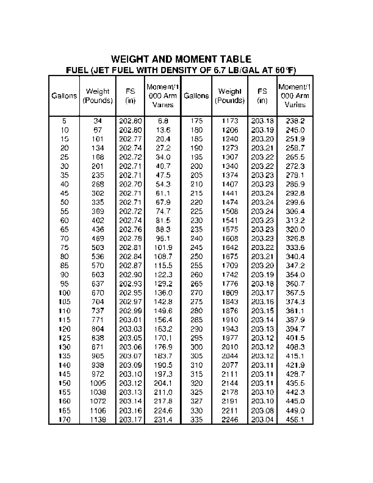
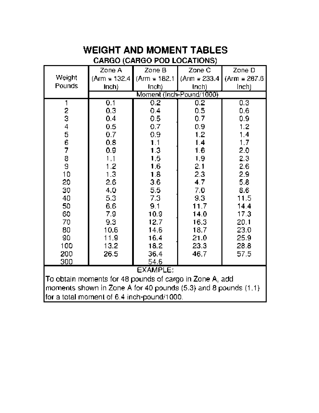
and balance, use the Sample Loading Problem, Weight and Moment
Tables, and Center of Gravity Moment Envelope as follows:
1.
Take the basic empty weight and moment from appropriate
weight and balance records carried in your airplane, and enter
them in the column titled “YOUR AIRPLANE” on the Sample
Loading Problem.
NOTE
In addition to the basic empty weight and moment noted on
these records, the C.G. arm (Fuselage Station) is also
shown, but need not be used on the Sample Loading
Problem. The moment which is shown must be divided by
1000 and this value used as the moment/1000 on the
loading problem.
2.
Use the Weight and Moment Tables to determine the moment/
1000 for each additional item to be carried, then list these on the
loading problem.
NOTE
Information on the Weight and Moment Tables for different
fuel grades is based on average fuel density at fuel
temperatures of
60°F. However, fuel weight increases
approximately
0.1 pounds per gallon for each
25°F
decrease in fuel temperature. Therefore, when
environmental conditions are such that the fuel temperature
is different than shown in the chart heading, a new fuel
weight calculation should be made using the 0.1 pounds
per gallon increase in fuel weight for each 25°F decrease in
fuel temperature. Assume the tanks are completely filled
and the fuel temperature is at 35°F (25°F below the 60°F
noted on the chart).
(Continued Next Page)
208BPHCUS-00
U.S.
6-9
SECTION 6
CESSNA
WEIGHT AND BALANCE/
MODEL 208B 867 SHP
EQUIPMENT LIST
GARMIN G1000
WEIGHT AND BALANCE (Continued)
3. Calculate the revised fuel weight by multiplying the total usable
fuel by the sum of the average density (stated on chart) plus the
increase in density estimated for the lower fuel temperature. In
this particular sample, as shown by the calculation below, the
resulting fuel weight increase due to lower fuel temperature will
be 32.0 pounds over the 2246 pounds (for 335 gallons) shown
on the chart, which might be significant in an actual loading
situation:
335 gallons X (6.7 + 0.1 pounds per gallon) = 2278 pounds
revised fuel weight.
Then calculate the revised fuel moment. The revised moment is
in direct proportion to the revised fuel weight:
X (revised moment)
= 2278 (revised weight)
456.1 (average moment)
= 2246 (average weight)
X = (456.1 X 2278) / 2246
The revised moment of X = 462.6. This value would be used on
the Sample Loading Problem as the moment/1000 in conditions
represented by this sample.
(Continued Next Page)
6-10
U.S.
208BPHCUS-00
CESSNA
SECTION 6
MODEL 208B 867 SHP
WEIGHT AND BALANCE/
GARMIN G1000
EQUIPMENT LIST
WEIGHT AND BALANCE (Continued)
NOTE
Information on the Weight and Moment Tables for crew,
passenger, and cargo is based on the pilot and front
passenger sliding seats positioned for average occupants
(e.g., Fuselage Station 135.5), the aft passenger fixed seats
(if installed) in the recommended position, and the baggage
or cargo uniformly loaded around the center (e.g., Fuselage
Station 172.1 in Zone 1) of the zone fore and aft boundaries
(e.g., Fuselage Stations 155.4 and 188.7 in Zone 1) shown
on Figure 6-11, Cabin Internal Loading Arrangements. For
loadings which may differ from these, the Loading
Arrangements figure and Sample Loading Problem lists
Fuselage Stations for these items to indicate their forward
and aft C.G. range limitations. Additional moment
calculations, based on the actual weight and C.G. arm
(Fuselage Station) of the item being loaded, must be made
if the position of the load is different from that shown on the
Weight and Moment Tables. For example, if seats are in
any position other than stated on Figure
6-11, Cabin
Internal Loading Arrangements, the moment must be
calculated by multiplying the occupant weight times the arm
in inches. A point nine inches forward of the intersection of
the seat bottom and seat back (with cushions compressed)
can be assumed to be the occupant C.G. For a reference in
determining the arm, the forward face of the raised aft
cargo floor is Fuselage Station 332.0.
Total
the weights and moments/1000 and plot these values on
the
Figure 6-18, Center of Gravity Moment Envelope to determine whether
the point falls within the envelope, and if the loading is acceptable.
WARNING
It is the responsibility of the pilot to make sure that
the airplane is correctly loaded. Operation outside
of prescribed weight and balance limitations could
result in an accident and serious or fatal injury.
(Continued Next Page)
208BPHCUS-00
U.S.
6-11
SECTION 6
CESSNA
WEIGHT AND BALANCE/
MODEL 208B 867 SHP
EQUIPMENT LIST
GARMIN G1000
WEIGHT AND BALANCE (Continued)
CLCALC
Loading calculations may also be completed using the CLCalc
application included in the CESNAV software package. CLCalc is
approved for use as an alternative source to the FAA Approved Weight
and Balance Manual to determine weight and balance data for a
particular flight. CLCalc and the Weight and Balance Manual methods
are each equally valid sources of weight and balance data; however,
the operator must use data from only one of these sources for a given
determination. Instructions for completing a loading calculation using
CLCalc are included in the Help menu of the CLCalc application.
(Continued Next Page)
6-12
U.S.
208BPHCUS-00
CESSNA
SECTION 6
MODEL 208B 867 SHP
WEIGHT AND BALANCE/
GARMIN G1000
EQUIPMENT LIST
WEIGHT AND BALANCE (Continued)
WEIGHT AND BALANCE RECORD (LOAD MANIFEST)
A Weight and Balance Record
(Load Manifest) is available for
recording the cargo loading configuration of each flight and verifying
that the airplane weight and takeoff center of gravity in terms of %
Mean Aerodynamic Chord (MAC) is acceptable. A sample of this record
is shown in this section. The procedure for using this record is
summarized below.
1. Enter flight date and number, point of departure and destination,
and airplane identification in spaces provided.
2. Enter weight of cargo in each cabin cargo zone in appropriate
ITEM WEIGHT spaces. Total cabin cargo weights in space
provided as a check that maximum allowable cabin cargo weight
of 3400 pounds is not exceeded. Refer to other portions of the
POH/AFM for additional limitations which must be observed.
3. Enter weight of cargo in cargo pod and weight of pilot, copilot,
and TKS fluid (if installed).
4. Complete ITEM INDEX column for all cargo, pilot, passenger,
and TKS fluid (if installed) by referring to adjacent WEIGHT
INDICES listing. For each cargo or personnel weight recorded
previously, read across horizontally to the vertical column having
an identical weight at the top. The number shown at this
intersection is the weight index for the recorded weight. As an
example, 300 pounds of cargo loaded in cabin Zone 1 has a
weight index of 988, and this number should be entered under
ITEM INDEX for cabin Zone 1.
(Continued Next Page)
208BPHCUS-00
U.S.
6-13
SECTION 6
CESSNA
WEIGHT AND BALANCE/
MODEL 208B 867 SHP
EQUIPMENT LIST
GARMIN G1000
WEIGHT AND BALANCE (Continued)
WEIGHT AND BALANCE RECORD (LOAD MANIFEST)
(Continued)
NOTE
If weight to be loaded does not match one of the weight
increments provided, and a more precise weight index is
needed, use the LOAD ITEM INDEX formula on the
backside of the Weight and Balance Record
(Load
Manifest) to calculate the index. However, as shown in the
sample calculation below for a 315-pound load (instead of
300 pounds) in cabin Zone 1, minor weight variables do not
affect the weight index significantly. The ARM used in the
following calculation is the centroid of cabin Zone 1 as
shown on the diagram on the backside of the record.
315 X (172.1 - 192) = -12.5
500
1000 - 12.5 = 987.5
The weight index of 987.5, when rounded to the next highest
number, would still result in the 988 given in the example above
for a 300-pounds load.
5. Add weight of pod cargo, pilot, passenger, and TKS fluid (if
installed) to sub-total weight for cabin cargo and enter this value
as the weight of the total payload; the sum of all item indices
recorded is the item index for the total payload. For calculation
purposes, enter only the last three digits of the total in the ITEM
INDEX columns.
(Continued Next Page)
6-14
U.S.
208BPHCUS-00
CESSNA
SECTION 6
MODEL 208B 867 SHP
WEIGHT AND BALANCE/
GARMIN G1000
EQUIPMENT LIST
WEIGHT AND BALANCE (Continued)
WEIGHT AND BALANCE RECORD (LOAD MANIFEST)
(Continued)
6.
Enter basic empty weight (from airplane weight and balance
information) in ITEM WEIGHT column for aircraft empty weight.
Calculate weight index using the BASIC AIRPLANE INDEX
formula on the backside of the Weight and Balance Record
(Load Manifest). The sample calculation below is for an airplane
with a basic empty weight of 5005 pounds and a C.G. arm of
185.69.
5005 X (185.69 - 192) + 500 = 436.84
500
In the aircraft empty weight spaces for the airplane in this
sample, a weight of 5005 and an index of 437 would be entered.
7.
Add aircraft empty weight and index to payload weight and index
to acquire a zero fuel weight and index. A plot of this weight and
index on the adjacent chart indicates the location of the zero fuel
weight center of gravity in terms of % MAC. A C.G. % MAC
space is provided to enter this value. If the zero fuel weight C.G.
falls well within clear area of chart envelope, the loading will
likely be acceptable. however, if the C.G. at this weight fall near
or within shaded area, a careful recheck of the loading and C.G.
is important.
8.
The weight available for takeoff fuel is the difference between
zero fuel weight and takeoff weight. A FUEL INDICES table at
bottom of Weight and Balance Record (Load Manifest) provides
an index for the weight of fuel to be carried. The fuel weight and
this index should be entered for takeoff fuel. When calculating
takeoff fuel, 35 pounds of additional fuel can be allowed as taxi
fuel under average conditions. A space for taxi fuel weight is
provided.
9.
Add takeoff fuel weight and index to zero fuel weight and index
to acquire a takeoff weight and index which can be plotted to
determine the takeoff C.G. location in terms of % MAC. A C.G. %
MAC space is provided for this value.
10. Enter 8807 pounds as the maximum allowable takeoff weight for
this airplane. The additional 35 pounds of taxi fuel provides a
maximum ramp weight of 8842 pounds.
208BPHCUS-00
U.S.
6-15
SECTION 6
CESSNA
WEIGHT AND BALANCE/
MODEL 208B 867 SHP
EQUIPMENT LIST
GARMIN G1000
WEIGHT AND BALANCE RECORD (LOAD MANIFEST)
Figure 6-3 (Sheet 1 of 2)
6-16
U.S.
208BPHCUS-00

CESSNA
SECTION 6
MODEL 208B 867 SHP
WEIGHT AND BALANCE/
GARMIN G1000
EQUIPMENT LIST
WEIGHT AND BALANCE RECORD (LOAD MANIFEST)
Figure 6-3 (Sheet 1 of 2)
208BPHCUS-00
U.S.
6-17
SECTION 6
CESSNA
WEIGHT AND BALANCE/
MODEL 208B 867 SHP
EQUIPMENT LIST
GARMIN G1000
CREW AND PASSENGER LOADING
The pilot and front passenger positions in all airplanes have six-way
adjustable seats. These seats slide forward and aft on tracks that have
adjustment holes for seat position.
The Passenger Version has aft passenger seating with two
configurations of Commuter Seating.
The first Commuter Seating configuration has three individual, fixed-
position passenger seats on the left side of the cabin, and three two
place fixed-position, bench seats located on the right side of the cabin
in a side-by-side arrangement.
The second Commuter Seating configuration includes four individual,
fixed-position, passenger seats on the left side of the cabin and four
individual, fixed-position passenger seats on the right side of the cabin
in a side-by-side arrangement.
WARNING
None of the airplane seats are approved for
installation facing aft.
6-18
U.S.
208BPHCUS-00
CESSNA
SECTION 6
MODEL 208B 867 SHP
WEIGHT AND BALANCE/
GARMIN G1000
EQUIPMENT LIST
BAGGAGE/CARGO LOADING
CABIN CARGO AREA
Cargo may be carried in the cabin of either the Cargo Version or the
Passenger Version. The cabin interior of the Cargo Version is
specifically equipped for carrying cargo. However, after seat removal
and the installation of miscellaneous equipment, the Passenger
Version will also fulfill the requirements of cargo missions. The following
paragraphs generally describe the cargo area of both versions.
To facilitate the carrying of large or bulky items, all aft seats (Passenger
Version Only) and the front passenger seat may be removed from the
airplane. If a cargo barrier and nets are available for installation,
removal of the front passenger seat may not be desired. Mission
requirements will dictate whether the barrier is to be used and the
number of seats removed. If seats are removed for hauling cargo and
the cargo barrier and nets are installed, the basic empty weight and
C.G. moment of the airplane should be adjusted so that these values
accurately represent the weight and moment of the airplane before
loading.
To calculate the new weight and moment, refer to the airplane
equipment list and acquire the weight and C.G. arm of each item of
equipment to be removed or added, then record these values on the
Sample Weight and Balance Record, to assist in the calculation. For
each item of equipment, multiply its weight by its C.G. arm to provide
the moment for that item. Subtract weights of removed items (seats)
and add weights of installed items (cargo barrier and nets) to the
original basic empty weight to provide a new basic empty weight.
Likewise, subtract the moments of removed items and add the
moments of installed items to the original moment to provide a new
airplane moment. Remember that the moment value is to be divided by
1000 to reduce the number of digits. The new basic empty weight and
moment/1000 can be used as illustrated in the Sample Loading
Problem when figuring airplane loading with the selected items of
equipment removed and/or installed.
(Continued Next Page)
208BPHCUS-00
U.S.
6-19
SECTION 6
CESSNA
WEIGHT AND BALANCE/
MODEL 208B 867 SHP
EQUIPMENT LIST
GARMIN G1000
BAGGAGE/CARGO LOADING (Continued)
CABIN CARGO AREA (Continued)
With all seats except the pilot’s seat removed, a large cabin volume is
available for baggage/cargo. If a cargo barrier is installed, the total
volume available for cargo behind the barrier is 340 cubic feet.
Cargo can be loaded through the large, almost square, two-piece cargo
door. The floor is flat from the firewall (FS 100.0) to the aft side of the
cargo door (FS 332.0), except for a small area around the rudder
pedals. This area is limited to a 200 pound per square foot maximum
allowable loading.
Between FS 332.0 and 356.0, additional cargo space is provided on a
floorboard raised approximately five inches above the main cabin floor.
The raised baggage/cargo area contains eight anchor plates where
quick-release tiedown fittings can be attached. This raised area is
limited to a maximum cargo capacity of 320 pounds.
In the front passenger seat area, FS 125.00 to 159.98, “I” section seat
tracks are installed where tiedown block assemblies can be clamped to
the tracks to serve as tiedown attachment points.
From FS 158.00 to 332.0, seat tracks are provided and designed to
receive quick-release tiedown fittings which can be snapped into the
tracks at 1.00 inch intervals.
If rope, cable or other fittings are used for tiedowns, they should be
rated at a minimum of 2100 pounds when used with all fittings noted in
Figure 6-10, Cargo Tie-Down Attachments. The only exception is the
double-stud quick-release tiedowns which require a 3150 pound rating.
(Continued Next Page)
6-20
U.S.
208BPHCUS-00
CESSNA
SECTION 6
MODEL 208B 867 SHP
WEIGHT AND BALANCE/
GARMIN G1000
EQUIPMENT LIST
BAGGAGE/CARGO LOADING (Continued)
CABIN CARGO AREA (Continued)
Strategically located nutplates are provided throughout the cabin which
allow for the installation of plywood flooring option (standard equipment
on Cargo Versions). The plywood flooring provides protection for the
floor structure, assists in the ease of loading cargo and helps with the
distribution of concentrated loads.
Maximum allowable cargo loads will be determined by the individual
zone weight limitation and by the airplane weight and C.G. limitations.
The number of tiedowns required is dependent on the load(s) to be
secured. Figure
6-10, Cargo Tie-Down Attachments, shows the
maximum allowable cargo weight for each type of cargo tiedown
attachment.
On Cargo Versions, the sidewalls in the cargo area are marked with
vertical lines to facilitate the identification of six loading zones.
Markings located on the sidewalls between the lines identify each zone
by number and display the maximum load which can be carried within
the zones. Refer to Figure 6-6, Cabin Internal Load Markings (Cargo
Version), for maximum zone weight limits.
CAUTION
The maximum load values marked in each zone are
predicated on all cargo being tied down within the
zones.
On Cargo Versions, a horizontal line labeled “75%” is prominently
marked along each sidewall as a loading reference. As indicated on a
placard on the lower cargo door, zones forward of the last loaded zone
must be at least 75% full by volume. Whenever possible, each zone
should be loaded to its maximum available volume prior to loading the
next zone. An additional placard located on the right sidewall between
Zones 5 and 6 cautions that if the load in Zone 5 exceeds 400 pounds,
a cargo partition net is required aft of the load or the load must be
secured to the floor. Refer to Figure 6-6, Cabin Internal Load Markings
(Cargo version), for additional details on installed placards and loading
requirements.
(Continued Next Page)
208BPHCUS-00
U.S.
6-21
SECTION 6
CESSNA
WEIGHT AND BALANCE/
MODEL 208B 867 SHP
EQUIPMENT LIST
GARMIN G1000
BAGGAGE/CARGO LOADING (Continued)
CABIN CARGO AREA (Continued)
CARGO BARRIER AND NETS
A cargo barrier and three barrier nets may be installed directly behind
the pilot’s and front passenger’s seats. The barrier and nets prevent
loose cargo from moving forward into the pilot’s and front passenger’s
area during an abrupt deceleration.
The barrier consists of a U-shaped divider constructed out of
honeycomb composite. The bottom portion of the barrier attaches to
the pilot and front passenger seat rails at four locations (FS 153.0). The
top portion attaches to cabin top structure at approximately FS 166.0.
The cargo barrier nets consist of three nets, one for the left sidewall,
one for the right sidewall, and one for the center. The left and right nets
fill in the space between the barrier assembly and the airplane
sidewalls. The side nets are fastened to the airplane sidewalls and the
edge of the barrier with six quick-release fasteners each, three on each
side. The center net fills in the opening in the top center of the barrier.
The center net is fastened with four fasteners, two on each side.
Horizontal lines labeled 75% are marked on the aft side of the cargo
barrier. Placards above the horizontal lines caution that the maximum
allowable load behind the barrier is 3400 pounds total, and that zones
forward of the last loaded zone must be at least 75% full by volume.
Refer to Figure 6-7, Cargo Barrier and Barrier Nets, for additional
details on installed placards and loading requirements.
(Continued Next Page)
6-22
U.S.
208BPHCUS-00
CESSNA
SECTION 6
MODEL 208B 867 SHP
WEIGHT AND BALANCE/
GARMIN G1000
EQUIPMENT LIST
BAGGAGE/CARGO LOADING (Continued)
CABIN CARGO AREA (Continued)
CARGO BARRIER AND NETS (Continued)
WARNING
•
When utilized, the cargo barrier and its attached
nets provide cargo forward crash load restraint
and protection of the pilot and front passenger;
however, the cargo must still be secured to
prevent it from shifting due to takeoff, flight,
landing,
and taxi
accelerations
and
decelerations.
•
On the passenger version, if passengers as well
as cargo, are located aft of the barrier, cargo
placement must allow movement and exit of the
passengers and the cargo must be secured for
crash load restraint conditions. Refer to Cargo
Load Restraint in this section for additional
information concerning cargo restraint with and
without a cargo barrier.
•
Make sure the barrier net fasteners are secured
for takeoff, landing, and inflight operations, and
are momentarily detached only for movement of
the nets for loading/unloading of items through
the crew area.
(Continued Next Page)
208BPHCUS-00
U.S.
6-23
SECTION 6
CESSNA
WEIGHT AND BALANCE/
MODEL 208B 867 SHP
EQUIPMENT LIST
GARMIN G1000
BAGGAGE/CARGO LOADING (Continued)
CABIN CARGO AREA (Continued)
CARGO PARTITION NETS
Cargo partition nets are available and can be installed to divide the
cargo area into convenient compartments. Partitions may be installed in
all of the five locations at FS 188.7, 246.8, 282.0, 307.0 and 332.0. The
cargo partitions are constructed of canvas with nylon webbing
reinforcement straps crisscrossing the partition for added strength. The
ends of the straps have quick-release fasteners which attach to the
floor tracks and two floor-mounted anchor plates located just forward of
the raised cargo floor and other anchor plates on the sidewalls and
ceiling. Four straps have adjustable buckles for tightening the straps
during installation of the partition. Refer to Figure 6-8, Cargo Partition
Nets, for additional details.
Zones divided by cargo partitions can be loaded without additional
tiedowns if a total loaded density for each partitioned zone does not
exceed 7.9 pounds per cubic foot and the zone is more than 75% full.
Cargo loading that does not meet these requirements must be secured
to the cabin floor.
CAUTION
The maximum cargo partition load is the sum of any
two zones. No more than two adjacent zones can be
divided by one partition. The partitions are designed to
prevent the cargo from shifting forward and aft in flight.
They should not be considered adequate to withstand
crash loads and do not replace the need for a cargo
barrier.
(Continued Next Page)
6-24
U.S.
208BPHCUS-00
CESSNA
SECTION 6
MODEL 208B 867 SHP
WEIGHT AND BALANCE/
GARMIN G1000
EQUIPMENT LIST
BAGGAGE/CARGO LOADING (Continued)
CABIN CARGO AREA (Continued)
CARGO TIEDOWNS AND ATTACHMENTS
Various tiedown belt assemblies and tiedown ring anchors are available
for securing cargo within the airplane. The belts may also be used for
tying down the airplane. A standard configuration consists of three
3000-pound rated belts with ratchet-type adjusters and six single-stud,
quick-release tiedown ring anchors.
A heavy-duty configuration consists of three 5000-pound rated belts
with ratchet-type adjusters and six double-stud, quick-release anchors.
Three 5000-pound rated belts with overcenter-type locking devices are
also available for heavy-duty use. The six single-stud and double-stud
tiedown ring anchors are also available separately. The single-stud
anchors can be attached to any tiedown point in the airplane that isn’t
placarded for attachment for partition nets only. The double-stud
anchors can be attached to the aft seat tracks only. Refer to Figure 6-
10, Cargo Tiedown Attachments, for maximum load ratings and
tiedown ring anchor spacing restrictions.
Refer to Maximum Zone/Compartment Loading table on the following
page for maximum zone weight limits.
(Continued Next Page)
208BPHCUS-00
U.S.
6-25
SECTION 6
CESSNA
WEIGHT AND BALANCE/
MODEL 208B 867 SHP
EQUIPMENT LIST
GARMIN G1000
BAGGAGE/CARGO LOADING (Continued)
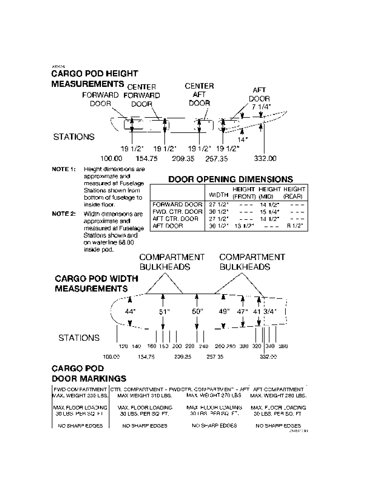
CARGO POD
The airplane can be equipped with an 111.5 cubic foot capacity cargo
pod attached to the bottom of the fuselage. The pod is divided into four
compartments (identified as Zones A, B, C, and D) by bulkheads and
has a maximum floor loading of 30 pounds per square foot and
maximum load weight limit of 1090 pounds.
Each compartment has a loading door located on the left side of the
pod. The doors are hinged at the bottom, and each has two latches.
When the latch handles are rotated to the horizontal position with the
doors closed, the doors are secured. Refer to Figure 6-5, Pod Internal
Dimension and Load Markings, and Figure 6-12, Cargo Pod Loading
Arrangements for additional information on loading cargo in the cargo
pod.
MAXIMUM ZONE/COMPARTMENT LOADINGS
Maximum zone loadings are as follows:
WEIGHT LIMITS (Pounds)
**UNSECURED
ZONE/
VOLUME
*SECURED
USING
C.G.
COMPART-
(CUBIC
BY
PARTITIONS OR
(STATION
MENT
FEET)
TIE-DOWNS IN CARGO POD LOCATION)
FUSELAGE
1
52.9
1780
415
172.1
2
109.0
3100
860
217.8
3
63.0
1900
495
264.4
4
43.5
1380
340
294.5
5
40.1
1270
315
319.5
6
31.5
320
245
344.0
CARGO POD A
23.4
- - -
230
132.4
B
31.5
- - -
310
182.1
C
27.8
- - -
270
233.4
D
28.8
- - -
280
287.6
* THIS IS THE MAXIMUM CARGO ALLOWED IN THE BAY INDICATED.
**DENSITY MUST BE 7.9 LBS/FT3 OR LESS AND BAY 75% OR MORE FULL.
6-26
U.S.
208BPHCUS-00
CESSNA
SECTION 6
MODEL 208B 867 SHP
WEIGHT AND BALANCE/
GARMIN G1000
EQUIPMENT LIST
BAGGAGE/CARGO LOADING (Continued)
CENTER OF GRAVITY PRECAUTIONS
Since the airplane can be used for cargo missions, carrying various
types of cargo in a variety of loading configurations, precautions must
be taken to protect the forward and aft C.G. limits. Load planning should
include a careful comparison of the mission requirements with the
volume and weight limitation in each loading zone and the final airplane
C.G. Cargo loaded in the forward zones may need to be balanced by
loading cargo in one or more aft zones. Conversely, loadings can not
be concentrated in the rear of the airplane, but must be compensated
by forward cargo to maintain balance. Under ideal conditions, loadings
should be accomplished with heavy items on the bottom and the load
distributed uniformly around the C.G. of the cabin cargo area zone and/
or cargo pod compartment.
Loading personnel must maintain strict accountability for loading
correctly and accurately, but may not always be able to achieve an
ideal loading. A means of protecting the C.G. aft limit is provided by
supplying an aft C.G. location warning area between 38.33% MAC and
the maximum allowable aft C.G. of 40.33% MAC. The warning area is
indicated by shading on Figure 6-17, Center of Gravity Limits, and
Figure 6-18, Center of Gravity Moment Envelope.
CAUTION
• This shaded area should be used only if accurate
C.G. determination can be obtained.
• Exercise caution while loading or unloading heavy
cargo through the cargo doors. An ideal loading in
every other respect can still cause tail tipping and
structural damage if proper weight distribution is
ignored. For example, heavy cargo loaded through
the doors and placed momentarily in Zones 4 and 5,
plus the weight of personnel required to move it to a
forward zone, could cause an out-of-balance
condition during loading.
208BPHCUS-00
U.S.
6-27
SECTION 6
CESSNA
WEIGHT AND BALANCE/
MODEL 208B 867 SHP
EQUIPMENT LIST
GARMIN G1000
CARGO LOAD RESTRAINT
PREVENTION OF MOVEMENT
Cargo restraint requires the prevention of movement in five principal
directions: forward, aft, upward (vertical), left (side), and right (side).
These movements are the result of forces exerted upon the cargo due
to acceleration or deceleration of the airplane in takeoffs and landings
as well as forces due to air turbulence in flight. Correct restraint
provides the proper relationship between airplane configuration (with or
without cargo barrier), weight of the cargo, and the restraint required.
Cargo must be tied down for flight, landing, and taxi load, and/or crash
load. When a cargo barrier is not installed, all cargo must be prevented
from movement in the five principal directions and secured to provide
crash load restraint. The maximum rated loads specified for loadings
without a cargo barrier is shown in Figure 6-10 (Sheet 1), Cargo
Tiedown Attachments, and should be used for each tiedown.
Consistent use of these loading criteria is important, and it is the
responsibility of the pilot to make sure the cargo is restrained properly.
When a cargo barrier is installed, cargo aft of the barrier must also be
secured to prevent movement in the five principal directions, but only to
the extent that shifting due to flight, landing, and taxi loads is provided.
The maximum rated loads specified for loadings with a cargo barrier
installed is shown in Figure
6-10
(Sheet
1), Cargo Tiedown
Attachments, and should be used for each tiedown. With a barrier
installed, all cargo must be loaded such that loading zones forward of
the last loaded zone must be 75% full by volume.
WARNING
In special loading arrangements which allow the
carriage of passengers as well as cargo behind the
barrier in the passenger version, all cargo must be
secured to prevent movement in the five principal
directions and provide the same crash load
restraint as though a barrier was not installed using
the maximum rated loads specified for loading
without a barrier. In this arrangement, cargo
placement must allow for movement and exit of the
passengers. The pilot must be responsible to make
sure proper load restraint in all loadings.
(Continued Next Page)
6-28
U.S.
208BPHCUS-00
CESSNA
SECTION 6
MODEL 208B 867 SHP
WEIGHT AND BALANCE/
GARMIN G1000
EQUIPMENT LIST
CARGO LOAD RESTRAINT (Continued)
PREVENTION OF MOVEMENT (Continued)
Refer to Figure 6-14, Typical Cargo Restraint Methods, for diagrams of
typical cargo tiedown methods for prevention of movement. Also, the
cargo partition nets available for the airplane can be installed at
Fuselage Stations 188.7, 246.8, 282.0, 307.0 and 332.0 to divide the
cabin cargo area into compartments. If the partitions are used, they
must be used in conjunction with the cargo barrier. Since partitions are
not designed to withstand crash loads, they cannot be considered as a
replacement for the barrier. Each partition will withstand the forward
and aft operational loads applied during takeoff, flight, and landing by
any two zones forward or aft of the partition. Use of the partitions will
allow loading of the zones without tying down the cargo if the load
density is not more than 7.9 pounds per cubic foot and the zone is more
than 75% full. Cargo loading that does not meet these requirements
must be secured to the cabin floor.
LOADING OF PIERCING OR PENETRATING ITEMS
Regardless of cargo location, items of a piercing or penetrating nature
shall be located so that other cargo is loaded between the barrier/nets,
cargo partitions, and rear wall and the piercing or penetrating items to
provide a buffer. The density of this cargo shall be sufficient to restrain
the piercing or penetrating items from passing through the barrier/nets,
partitions, and rear wall under critical emergency landing conditions. If
the condition cannot be complied with, the piercing or penetrating items
shall be tied down separately.
208BPHCUS-00
U.S.
6-29
SECTION 6
CESSNA
WEIGHT AND BALANCE/
MODEL 208B 867 SHP
EQUIPMENT LIST
GARMIN G1000
TRANSPORTATION OF HAZARDOUS MATERIALS
Special protection of the airplane and training of personnel are key
considerations in conducting approved transportation of hazardous
materials.
Protection against hazardous materials has been provided in the
fuselage bilge area under the cargo compartment from Fuselage
Station 168.0 to 356.0, and these materials may be carried in any
location within this area.
In addition to the pilot-in-command and flight crew member (if used),
other personnel such as cargo receiving and loading personnel should
be properly trained concerning the acceptance, handling, storage,
loading and unloading of hazardous materials if these materials are to
be carried. Information and regulations pertaining to the air
transportation of hazardous materials is outlined in the Code of Federal
Regulations
(CFR) Title
49 and in the International Civil Aviation
Organization (ICAO) Technical Instructions for the Safe Transport of
Dangerous Goods by Air.
EQUIPMENT LIST
For a complete list of equipment installed in the airplane as delivered
from the manufacturer, refer to the equipment list furnished with the
airplane.
6-30
U.S.
208BPHCUS-00

CESSNA
SECTION 6
MODEL 208B 867 SHP
WEIGHT AND BALANCE/
GARMIN G1000
EQUIPMENT LIST
CABIN INTERNAL DIMENSIONS
(CARGO VERSION)
Figure 6-4 (Sheet 1 of 2)
208BPHCUS-00
U.S.
6-31

SECTION 6
CESSNA
WEIGHT AND BALANCE/
MODEL 208B 867 SHP
EQUIPMENT LIST
GARMIN G1000
CABIN INTERNAL DIMENSIONS
(PASSENGER VERSION)
Figure 6-4 (Sheet 2)
6-32
U.S.
208BPHCUS-00
CESSNA
SECTION 6
MODEL 208B 867 SHP
WEIGHT AND BALANCE/
GARMIN G1000
EQUIPMENT LIST
POD INTERNAL DIMENSIONS AND LOAD MARKINGS
Figure 6-5
208BPHCUS-00
U.S.
6-33

SECTION 6
CESSNA
WEIGHT AND BALANCE/
MODEL 208B 867 SHP
EQUIPMENT LIST
GARMIN G1000
CABIN INTERNAL LOAD MARKINGS
(CARGO VERSION)
Figure 6-6
6-34
U.S.
208BPHCUS-00

CESSNA
SECTION 6
MODEL 208B 867 SHP
WEIGHT AND BALANCE/
GARMIN G1000
EQUIPMENT LIST
CARGO BARRIER AND BARRIER NETS
NOTE
• Installation of the fire extinguisher on the cargo barrier is
not shown.
• The cargo barrier and attached barrier nets must be
installed to provide forward crash load restraint.
• The quick-release fasteners which secure the center and
side barrier nets allow momentary detachment of the
nets for loading and unloading of items through the crew
area.
Figure 6-7
208BPHCUS-00
U.S.
6-35

SECTION 6
CESSNA
WEIGHT AND BALANCE/
MODEL 208B 867 SHP
EQUIPMENT LIST
GARMIN G1000
CARGO PARTITION NETS
NOTE
• Partition nets are available for installation at Fuselage Stations 188.7,
246.8, 282.0, 307.0 and 332.0.
• If partitions are used, they must be used in conjunction with the cargo
barrier. Partitions are not designed to withstand crash loads, therefore
they cannot be considered as a replacement for the barrier.
• Each partition will withstand the forward and aft operational loads applied
during takeoff, flight, and landing by any two zones forward or aft of the
partition. Use of the partitions will allow loading of the zones without tying
down the cargo if the load density is no more than 7.9 pounds per cubic
foot and the zone is more than 75% full. Cargo loading that does not meet
these requirements must be secured to the cabin floor.
Figure 6-8
6-36
U.S.
208BPHCUS-00

CESSNA
SECTION 6
MODEL 208B 867 SHP
WEIGHT AND BALANCE/
GARMIN G1000
EQUIPMENT LIST
MAXIMUM CARGO SIZES
NOTE
1. Approximately one inch clearance allowed from sidewall and
ceiling.
2. Subtract roller height and pallet thickness, if applicable.
Figure 6-9
208BPHCUS-00
U.S.
6-37

SECTION 6
CESSNA
WEIGHT AND BALANCE/
MODEL 208B 867 SHP
EQUIPMENT LIST
GARMIN G1000
CARGO TIEDOWN ATTACHMENTS
Figure 6-10 (Sheet 1 of 2)
6-38
U.S.
208BPHCUS-00

CESSNA
SECTION 6
MODEL 208B 867 SHP
WEIGHT AND BALANCE/
GARMIN G1000
EQUIPMENT LIST
CARGO TIEDOWN ATTACHMENTS
Figure 6-10 (Sheet 2)
208BPHCUS-00
U.S.
6-39

SECTION 6
CESSNA
WEIGHT AND BALANCE/
MODEL 208B 867 SHP
EQUIPMENT LIST
GARMIN G1000
CABIN INTERNAL LOADING ARRANGEMENTS
(CARGO VERSION)
NOTE
1. * Pilot or front passenger center of gravity on adjustable seats
positioned for an average occupant with the seat locking pin
at Fuselage Station 145.0. Numbers in parentheses indicate
forward and aft limits of occupant center of gravity range.
2. ** Cargo area center of gravity in Zones 1 thru 6 based on the
mid point of the zone.
3.
Vertical lines marked on the cargo area sidewalls or the
forward face of the raised floor (Fuselage Station 332.0) can
be used as a convenient reference point for determining the
location of occupant or cargo Fuselage Station.
Figure 6-11 (Sheet 1 of 3)
6-40
U.S.
208BPHCUS-00

CESSNA
SECTION 6
MODEL 208B 867 SHP
WEIGHT AND BALANCE/
GARMIN G1000
EQUIPMENT LIST
CABIN INTERNAL LOADING ARRANGEMENTS
(PASSENGER VERSION)
NOTE
1. * Pilot or front passenger center of gravity on adjustable seats
positioned for an average occupant with the seat locking pin
at FS 145.0. Numbers in parentheses indicate forward and
aft limits of occupant center of gravity range.
2. ** Cargo area center of gravity in Zones 1 thru 6 based on the
mid point of the zone.
3.
The forward face of the raised floor (FS 332.0) can be used
as a convenient reference point for determining the location
of occupant or cargo Fuselage Stations.
4.
When a cargo barrier is installed, two-place Commuter seat
4 and 5 or individual Commuter seats 3 and 4 must be
removed. Mission requirements will dictate if any aft
passenger seating is to remain installed.
Figure 6-11 (Sheet 2)
208BPHCUS-00
U.S.
6-41

SECTION 6
CESSNA
WEIGHT AND BALANCE/
MODEL 208B 867 SHP
EQUIPMENT LIST
GARMIN G1000
CABIN INTERNAL LOADING ARRANGEMENTS
(PASSENGER VERSION)
Figure 6-11 (Sheet 3)
6-42
U.S.
208BPHCUS-00

CESSNA
SECTION 6
MODEL 208B 867 SHP
WEIGHT AND BALANCE/
GARMIN G1000
EQUIPMENT LIST
CARGO POD LOADING ARRANGEMENT
NOTE
1. * Cargo bay center of gravity in Zones A, B, C, and D.
2.
Compartment bulkheads that separate Zones A and B (FS
154.75), Zones B and C (FS 209.35), and Zones C and D
(FS 257.35) can be used as a reference point for determining
the location of cargo Fuselage Stations.
Figure 6-12
208BPHCUS-00
U.S.
6-43

SECTION 6
CESSNA
WEIGHT AND BALANCE/
MODEL 208B 867 SHP
EQUIPMENT LIST
GARMIN G1000
LOADING/TIEDOWN BY ZONE AND LOAD
(OFF- LOADING SEQUENCE)
NOTE
1.
If cargo partitions are not utilized, individual loads must be
secured by adequate tiedowns over tarps.
2.
Protection against hazardous materials has been provided in
the fuselage bilge area under the cargo compartment from
FS 168.0 to 356.0. These materials can be carried in any
location within this area.
Figure 6-13
6-44
U.S.
208BPHCUS-00

CESSNA
SECTION 6
MODEL 208B 867 SHP
WEIGHT AND BALANCE/
GARMIN G1000
EQUIPMENT LIST
TYPICAL CARGO RESTRAINT METHODS
Figure 6-14
208BPHCUS-00
U.S.
6-45

SECTION 6
CESSNA
WEIGHT AND BALANCE/
MODEL 208B 867 SHP
EQUIPMENT LIST
GARMIN G1000
WEIGHT AND MOMENT TABLES
PILOT AND FRONT PASSENGER
(CARGO VERSION)
Figure 6-15 (Sheet 1 of 7)
6-46
U.S.
208BPHCUS-00

CESSNA
SECTION 6
MODEL 208B 867 SHP
WEIGHT AND BALANCE/
GARMIN G1000
EQUIPMENT LIST
Figure 6-15 (Sheet 2)
208BPHCUS-00
U.S.
6-47

SECTION 6
CESSNA
WEIGHT AND BALANCE/
MODEL 208B 867 SHP
EQUIPMENT LIST
GARMIN G1000
Figure 6-15 (Sheet 3)
6-48
U.S.
208BPHCUS-00
CESSNA
SECTION 6
MODEL 208B 867 SHP
WEIGHT AND BALANCE/
GARMIN G1000
EQUIPMENT LIST
Figure 6-15 (Sheet 4)
208BPHCUS-00
U.S.
6-49

SECTION 6
CESSNA
WEIGHT AND BALANCE/
MODEL 208B 867 SHP
EQUIPMENT LIST
GARMIN G1000
Figure 6-15 (Sheet 6)
6-50
U.S.
208BPHCUS-00
CESSNA
SECTION 6
MODEL 208B 867 SHP
WEIGHT AND BALANCE/
GARMIN G1000
EQUIPMENT LIST
Figure 6-15 (Sheet 7)
208BPHCUS-00
U.S.
6-51

SECTION 6
CESSNA
WEIGHT AND BALANCE/
MODEL 208B 867 SHP
EQUIPMENT LIST
GARMIN G1000
Figure 6-16 (Sheet 1 of 2)
6-52
U.S.
208BPHCUS-00

CESSNA
SECTION 6
MODEL 208B 867 SHP
WEIGHT AND BALANCE/
GARMIN G1000
EQUIPMENT LIST
Figure 6-16 (Sheet 2)
208BPHCUS-00
U.S.
6-53

SECTION 6
CESSNA
WEIGHT AND BALANCE/
MODEL 208B 867 SHP
EQUIPMENT LIST
GARMIN G1000
CENTER OF GRAVITY LIMITS
WARNING
It is the responsibility of the pilot to make sure that
the airplane is loaded correctly. Operation outside
of prescribed weight and balance limitations could
result in an accident and serious or fatal injury.
Figure 6-17
6-54
U.S.
208BPHCUS-00

CESSNA
SECTION 6
MODEL 208B 867 SHP
WEIGHT AND BALANCE/
GARMIN G1000
EQUIPMENT LIST
CENTER OF GRAVITY MOMENT ENVELOPE
WARNING
• Because loading personnel may not always be
able to achieve an ideal loading, a means of
protecting the C.G envelope is provided by
supplying an aft C.G. location warning (shaded
area) between 38.33% mac and the maximum aft
c.g. of
40.33% mac on the center of gravity
moment envelope. Points falling within this
shaded area should be used only if accurate C.G.
determination for cargo loadings can be
obtained.
• It is the responsibility of the pilot to make sure
that the airplane is loaded correctly. Operation
outside of prescribed weight and balance
limitations could result in an accident and
serious or fatal injury.
Figure 6-18
208BPHCUS-00
U.S.
6-55
SECTION 6
CESSNA
WEIGHT AND BALANCE/
MODEL 208B 867 SHP
EQUIPMENT LIST
GARMIN G1000
This Page Intentionally Left Blank
6-56
U.S.
208BPHCUS-00
CESSNA
SECTION 7
MODEL 208B 867 SHP AIRPLANE AND SYSTEMS DESCRIPTION
GARMIN G1000
AIRPLANE AND SYSTEMS DESCRIPTIONS
TABLE OF CONTENTS
Page
Introduction
7-7
Airframe
7-8
Cargo Pod
7-10
Flight Controls
7-11
Trim Systems
7-11
Flight Control and Trim System
7-12
Instrument Panel
7-15
Garmin Interfaces
7-15
Panel Layout
7-16
Control Pedestal
7-16
Instrument Panel
7-17
Left Sidewall Switch and Circuit Breaker Panel
7-19
Overhead Panel
7-19
Left Sidewall Switch and Circuit Breaker Panel
7-21
Annunciators
7-22
Ground Control
7-25
Minimum Turning Radius
7-26
Wing Flap System
7-27
Landing Gear System
7-29
Baggage/Cargo Compartment
7-29
Seats
7-30
Pilot's and Copilot's Seats
7-30
Aft Passengers’ Seats (Commuter) (Passenger Version)
7-31
Aft Passengers’ Seats (Utility) (Passenger Version)
7-31
Headrests
7-31
Seat Belts and Shoulder Harnesses
7-32
Seat Belts, Strap, and Shoulder Harnesses
(Pilot and Copilot seats)
7-35
Cabin Entry Doors
7-37
Crew Entry Doors
7-37
Passenger Entry Door (Passenger Version Only)
7-38
(Continued Next Page)
208BPHCUS-00
U.S.
7-1
SECTION 7
CESSNA
AIRPLANE AND SYSTEMS DESCRIPTION
MODEL 208B 867 SHP
GARMIN G1000
TABLE OF CONTENTS (Continued)
Page
Cargo Doors
7-41
Cabin Windows
7-44
Control Locks
7-45
Engine
7-46
Typical Engine Components
7-49
Engine Controls
7-49
Power Lever
7-49
Emergency Power Lever
7-50
Propeller Control Lever
7-52
Fuel Condition Lever
7-52
Quadrant Friction Lock
7-52
Engine Indicating System (EIS)
7-53
Torque Indications
7-54
Propeller RPM Indications
7-55
ITT Indication
7-55
Gas Generator RPM Indications
7-56
Fuel Flow Indications
7-56
Oil Pressure Indication
7-57
Oil Temperature Indication
7-57
New Engine Break-In and Operation
7-58
Engine Lubrication System
7-59
Firewall Oil Shutoff Valve
7-60
Ignition System
7-61
Air Induction System
7-62
Inertial Separator System
7-63
Engine Air Flow
7-64
Exhaust System
7-65
Engine Fuel System
7-65
Cooling System
7-66
Starting System
7-67
(Continued Next Page)
7-2
U.S.
208BPHCUS-00
CESSNA
SECTION 7
MODEL 208B 867 SHP AIRPLANE AND SYSTEMS DESCRIPTION
GARMIN G1000
TABLE OF CONTENTS (Continued)
Page
Engine Accessories
7-67
Oil Pump
7-68
Fuel Pump
7-68
Ng Tachometer-Generator
7-68
Propeller Tachometer-Generator
7-69
Torquemeter
7-69
Starter-Generator
7-69
Interstage Turbine Temperature Sensing System
. 7-70
Propeller Governor
7-70
Torque Limiter
7-71
Propeller Overspeed Governor
7-72
Engine Fire Detection System
7-72
Engine Gear Reduction System
7-73
Chip Detectors
7-74
Oil Breather Drain Can
7-74
Propeller
7-75
Overspeed Governor Test Switch
7-76
Fuel System
7-76
Fuel Quantity Data
7-79
Firewall Fuel Shutoff Valve
7-80
Fuel Tank Selectors
7-80
Fuel Selectors Off Warning System
7-81
Fuel Boost Pump Switch
7-82
Fuel Flow Indication
7-83
Fuel Quantity Indications
7-84
Wing Tank Fuel Low Caution Annunciator
7-84
Reservoir Fuel Low Warning Annunciator
7-85
Fuel Pressure Low Warning Annunciator
7-85
Fuel Boost Pump On Annunciator
7-85
Drain Valves
7-86
Fuel Ecology Tank
7-87
Fuel Pump Drain Reservoir
7-87
Brake System
7-88
(Continued Next Page)
208BPHCUS-00
U.S.
7-3
SECTION 7
CESSNA
AIRPLANE AND SYSTEMS DESCRIPTION
MODEL 208B 867 SHP
GARMIN G1000
TABLE OF CONTENTS (Continued)
Page
Electrical System
7-89
Standby Electrical System
7-89
Generator Control Unit
7-89
Ground Power Monitor
7-90
Battery Switch
7-90
Starter Switch
7-91
Ignition Switch
7-91
Generator Switch
7-91
Standby Alternator Power Switch
7-92
Avionics Power Switches
7-92
Avionics Standby Power Switch
7-92
Avionics Bus Tie Switch
7-93
Electrical System
7-94
External Power Switch
7-97
Circuit Breakers
7-97
Voltage and Amperage Display
7-98
Ground Service Plug Receptacle
7-98
Lighting Systems
7-99
Exterior Lighting
7-99
Navigation Lights
7-99
Landing Lights
7-99
Taxi/Recognition Lights
7-99
Strobe Lights
7-100
Flashing Beacon Light
7-100
Wing Inspection Light
7-100
Courtesy Lights
7-100
(Continued Next Page)
7-4
U.S.
208BPHCUS-00
CESSNA
SECTION 7
MODEL 208B 867 SHP AIRPLANE AND SYSTEMS DESCRIPTION
GARMIN G1000
TABLE OF CONTENTS (Continued)
Page
Interior Lighting
7-102
Garmin Displays, Optional ADF, and
HF Displays (if installed)
7-102
Standby Indicator Control Knob
7-102
LED Panels/ANNUN Control Knob
7-103
Center Flood/Map Panel Knob
7-103
Left Flood/Map Lighting Control Knob
7-103
Right Flood/Map Lighting Control Knob
7-103
Control Wheel Maplights
7-103
Cabin Lights without Timer (208B Passenger)
7-104
Cabin Lights with Timer (if installed)
7-104
Cabin Lights with Timer (Super Cargomaster)
7-105
Passenger Reading Lights (Passenger Version Only)
7-105
No Smoke/Seat Belt Sign (Passenger Version Only)
7-105
Cabin Heating, Ventilating And Defrosting System
7-106
Bleed Air Heat Switch
7-106
Temperature Selector Knob
7-107
Cabin Heating, Ventilating and
Defrosting System (Cargo Version)
7-108
Cabin Heating, Ventilating and
Defrosting System (Passenger Version)
7-109
Mixing Air Push-Pull Control
7-110
Aft/Forward Cabin Push-Pull Control
7-111
Defrost/Forward Cabin Push-Pull Control
7-111
Cabin Heat Firewall Shutoff Knob
7-112
Vent Air Control Knobs
7-112
Instrument Panel Vent Knobs
7-113
Ventilating Outlets
7-113
Oxygen System
7-113
(Continued Next Page)
208BPHCUS-00
U.S.
7-5
SECTION 7
CESSNA
AIRPLANE AND SYSTEMS DESCRIPTION MODEL 208B 867 SHP
GARMIN G1000
TABLE OF CONTENTS (Continued)
Page
Pitot-Static System And Instruments
7-114
Airspeed Indicators
7-115
Vertical Speed Indicators
7-115
Altimeter (Standby Instrument Panel)
7-115
Vacuum System and Instruments
7-116
Attitude Indicator (Standby Instrument Panel)
7-116
Low-Vacuum Warning Flag
7-116
Vacuum System
7-117
Stall Warning System
7-118
Avionics Support Equipment
7-119
Avionics Cooling Fan
7-119
Microphone-Headset Installations
7-119
Static Dischargers
7-120
12 VDC Power Outlet
7-120
Auxiliary Audio Input Jack
7-121
Cabin Features
7-122
Cabin Fire Extinguisher
7-122
Sun Visors
7-123
Chart and Storage Compartments
7-123
Miscellaneous Equipment
7-123
Engine Inlet Covers and Propeller Anchors
7-123
Crew Entry Step Assembly
7-124
Cargo Barrier and Nets
7-124
Cargo Partitions
7-125
Cargo Door Restraining Net
7-125
Cargo/Airplane Tie-down Equipment
7-125
Hoisting Rings
7-126
Relief Tube
7-126
Oil Quick-drain Valve
7-126
7-6
U.S.
208BPHCUS-00
CESSNA
SECTION 7
MODEL 208B 867 SHP AIRPLANE AND SYSTEMS DESCRIPTION
GARMIN G1000
INTRODUCTION
This section provides description and operation of the airplane and its
systems. Some equipment described herein is optional and may not be
installed in the airplane. Refer to Section 9, Supplements, for details of
other optional systems and equipment.
WARNING
Complete familiarity with the airplane and its
systems will not only increase the pilot's
proficiency and ensure optimum operation, but
could provide a basis for analyzing system
malfunctions in case an emergency is encountered.
Information in this section will assist in that
familiarization. The responsible pilot will want to be
prepared to make proper and precise responses in
every situation.
208BPHCUS-00
U.S.
7-7
SECTION 7
CESSNA
AIRPLANE AND SYSTEMS DESCRIPTION MODEL 208B 867 SHP
GARMIN G1000
AIRFRAME
The airplane is an all metal, high wing, single-engine airplane equipped
with tricycle landing gear and designed for general utility purposes.
The construction of the fuselage is of conventional aluminum bulkhead,
stringer, and skin design commonly known as semimonocoque. Major
components of structure include the front and rear carry-through spars
to which the wings are attached, a bulkhead and forgings for main
landing gear attachment and a bulkhead with attaching plates at its
base for the strut-to-fuselage attachment of the wing struts.
The externally braced wings, containing integral fuel tanks, are
constructed of a front and rear spar with formed sheet metal ribs,
doublers, and stringers. The entire structure is covered with aluminum
skin. The front spars are equipped with wing-to-fuselage and wing-to-
strut attach fittings. The aft spars are equipped with wing-to-fuselage
attach fittings. The integral fuel tanks are formed by the front and rear
spars, upper and lower skins, and inboard and outboard closeout ribs.
Extensive use of bonding is used in the fuel tank area to reduce fuel
tank sealing.
Round-nosed ailerons and single-slot type flaps are attached to the
trailing edge of the wings. The ailerons are constructed from
conventional formed sheet metal ribs and smooth aluminum skin
construction. A slot lip spoiler, mounted above the outboard end of
each flap, is of conventional construction. The left aileron incorporates
a servo tab while the right aileron incorporates a trimmable servo tab,
both mounted on the outboard end of the aileron trailing edge.
(Continued Next Page)
7-8
U.S.
208BPHCUS-00
CESSNA
SECTION 7
MODEL 208B 867 SHP AIRPLANE AND SYSTEMS DESCRIPTION
GARMIN G1000
AIRFRAME (Continued)
The empennage (tail assembly) consists of a conventional vertical
stabilizer, rudder, horizontal stabilizer, and elevator. The vertical
stabilizer consists of a forward and aft spar, formed sheet metal ribs
and reinforcements, four skin panels, formed leading edge skins, and a
dorsal fin.
The rudder is constructed of a forward and aft spar, formed sheet metal
ribs and reinforcements, and a wrap-around skin panel. The top of the
rudder incorporates a leading edge extension which contains a balance
weight.
The horizontal stabilizer is constructed of a forward and aft spar, ribs
and stiffeners, four upper and four lower skin panels, and two left and
two right wrap-around skin panels which also form the leading edges.
The horizontal stabilizer also contains dual jack screw type actuators
for the elevator trim tabs.
Construction of the elevator consists of a forward and aft spar, sheet
metal ribs, upper and lower skin panels, and wrap-around skin panels
for the leading and trailing edges. An elevator trim tab is attached to the
trailing edge of each elevator by full length piano-type hinges. Dual
pushrods from each actuator located in the horizontal stabilizer transmit
actuator movement to dual horns on each elevator trim tab to provide
tab movement. Both elevator tip leading edge extensions provide
aerodynamic balance and incorporate balance weights. A row of vortex
generators on the top of the horizontal stabilizer just forward of the
elevator enhances nose down elevator and trim authority.
208BPHCUS-00
U.S.
7-9
SECTION 7
CESSNA
AIRPLANE AND SYSTEMS DESCRIPTION MODEL 208B 867 SHP
GARMIN G1000
CARGO POD
The airplane may be equipped with a cargo pod which provides
additional cargo space. The pod attaches to the bottom of the fuselage
with screws and can be removed, if desired, for increased performance
and useful load. The pod and doors are fabricated with a Nomex inner
housing, a layer of Kevlar, and an outer layer of fiberglass. Complete
instructions for removal and installation of the cargo pod are contained
in the
208 Maintenance Manual, Chapter 25-52-00, Cargo Pod -
Maintenance Practices.
The volume of the cargo pod is 111.5 cubic feet and has a load-carrying
capacity of 1090 pounds (494 kg). The pod has aluminum bulkheads
that divide it into four separate compartments. Each compartment has a
door on the left side of the pod that is hinged at the bottom. Each door
has two handles that latch the doors in the closed position when rotated
90 degrees to the horizontal position.
7-10
U.S.
208BPHCUS-00
CESSNA
SECTION 7
MODEL 208B 867 SHP AIRPLANE AND SYSTEMS DESCRIPTION
GARMIN G1000
FLIGHT CONTROLS
The airplane's flight control system, refer to Figure 7-1, consists of
conventional aileron, rudder, and elevator control surfaces and a pair of
spoilers mounted above the outboard ends of the flaps. The control
surfaces are manually operated through mechanical linkage using a
control wheel for the ailerons, spoilers and elevator and rudder/brake
pedals for the rudder. The wing spoilers improve lateral control of the
airplane at low speeds by disrupting lift over the appropriate flap. The
spoilers are interconnected with the aileron system through a push-rod
mounted to an arm on the aileron bell crank. Spoiler travel is
proportional to aileron travel for aileron deflections in excess of 5° up.
The spoilers are retracted throughout the remainder of aileron travel.
Aileron servo tabs provide reduced maneuvering control wheel forces.
TRIM SYSTEMS
Manually operated aileron, elevator, and rudder trim systems are
provided, refer to Figure 7-1.
The aileron is trimmed by a servo tab attached to the right aileron which
is mechanically controlled by the AILERON TRIM control knob located
on the control pedestal to the left of the FUEL/OIL SHUTOFF knob.
Rotating the AILERON TRIM control knob to the right (clockwise) will
trim the right wing down; conversely, rotating it to the left
(counterclockwise) will trim the left wing down.
The elevator is trimmed through two elevator trim tabs by utilizing the
vertically mounted ELEVATOR TRIM control wheel located on left side
of the control pedestal. Forward rotation of the ELEVATOR TRIM
control wheel will trim nose-down; conversely, aft rotation will trim nose-
up. The airplane is also equipped with an electric elevator trim system.
The rudder is trimmed through the nosewheel steering bungee
connected to the rudder control system and a RUD TRIM control wheel
mounted on the control pedestal. This is accomplished by rotating the
horizontally mounted RUD TRIM control wheel either left or right to the
desired trim position. Rotating the RUD TRIM wheel to the right will trim
nose-right; conversely; rotating it to the left will trim nose-left.
208BPHCUS-00
U.S.
7-11

SECTION 7
CESSNA
AIRPLANE AND SYSTEMS DESCRIPTION MODEL 208B 867 SHP
GARMIN G1000
FLIGHT CONTROL AND TRIM SYSTEMS
Figure 7-1 (Sheet 1 of 3)
7-12
U.S.
208BPHCUS-00

CESSNA
SECTION 7
MODEL 208B 867 SHP AIRPLANE AND SYSTEMS DESCRIPTION
GARMIN G1000
FLIGHT CONTROL AND TRIM SYSTEMS
Figure 7-1 (Sheet 2 of 3)
208BPHCUS-00
U.S.
7-13

SECTION 7
CESSNA
AIRPLANE AND SYSTEMS DESCRIPTION MODEL 208B 867 SHP
GARMIN G1000
FLIGHT CONTROL AND TRIM SYSTEMS
Figure 7-1 (Sheet 3 of 3)
7-14
U.S.
208BPHCUS-00
CESSNA
SECTION 7
MODEL 208B 867 SHP AIRPLANE AND SYSTEMS DESCRIPTION
GARMIN G1000
INSTRUMENT PANEL
The instrument panel, refer to Figure 7-2, is of all metal construction
and is installed in sections so equipment can be easily removed for
maintenance. The glareshield, above and projecting aft from the
instrument panel, limits undesirable reflections on the windshield from
lighted equipment and displays mounted in the instrument panel.
Additional controls and displays are mounted on a control pedestal
extending from the center of the instrument panel to the floor, on a
separate panel mounted on the left sidewall, and on an overhead panel.
GARMIN INTERFACES
The interfaces to the Garmin system are three Garmin Display Units
(GDUs), an audio panel, and an autopilot mode controller. The three
GDUs are configured as two Primary Flight Displays (PFDs) and one
Multifunction Flight Display (MFD). Refer to the Garmin G1000 CRG for
specific operating information on all Garmin equipment.
The PFDs, centered above the control wheels in front of the pilot and
copilot, show the primary flight instruments and display any Crew Alert
System
(CAS) annunciations, messages and alerts. During
reversionary operation (MFD or PFD 1 failure) or when the DISPLAY
BACKUP switch is selected, the Engine Indication System (EIS) is
shown on the PFD.
The MFD, located between the two PFDs, depicts EIS information
along the left side of the display and shows navigation, terrain, lightning
and traffic data on the moving map. Flight management or display
configuration information can be shown on the MFD in place of the
moving map pages.
The Garmin audio panel is located between the pilot PFD and the MFD.
It integrates all of the communication and navigation digital audio
signals, intercom system and marker beacon controls. A pushbutton
switch labeled DISPLAY BACKUP allows manual selection of
reversionary mode for the PFDs and MFD.
The Garmin autopilot mode controller, located above the MFD, is the
pilot interface with the autopilot system.
208BPHCUS-00
U.S.
7-15
SECTION 7
CESSNA
AIRPLANE AND SYSTEMS DESCRIPTION MODEL 208B 867 SHP
GARMIN G1000
PANEL LAYOUT
To the left of the pilot PFD is a switch panel which has many of the
switches necessary to operate the airplane systems. At lower left are a
circuit breaker panel for avionics systems, the left fresh air outlet and
pull knob, test switches for prop overspeed, fire detection, and fuel
selection warning systems, microphone and headset jacks and an
alternate static source valve.
Below the MFD are standby indicators for airspeed, attitude, altitude,
and torque. Below these indicators are the parking brake, light dimming
controls, inertial separator control, and cabin heat controls. Provisions
are included for optional air conditioning controls and HF and ADF
displays.
At lower right are the map compartment, right fresh air outlet and pull
knob, and microphone and headset jacks. At upper right are the hour
meter and ELT remote switch. Mounted above the glare shield is a
magnetic compass. For details concerning the instruments, switches,
and controls on this panel, refer in this section to the description of the
systems to which these items are related.
CONTROL PEDESTAL
A control pedestal, extending from the center of the instrument panel to
the floor, contains the EMERGENCY POWER lever, POWER lever,
PROP RPM lever, FUEL CONDITION lever, WING FLAPS selector and
position indicator, elevator, rudder and aileron trim controls with
position indicators, the FUEL/OIL SHUTOFF knob, CABIN HEAT
FIREWALL SHUTOFF control, a microphone, 12VDC power outlet, and
an auxiliary audio input jack
Equipment mounted on this panel is illustrated in Figure 7-2. For details
concerning the instruments, switches, and controls on the pedestal,
refer to the description of the systems to which these items are related.
7-16
U.S.
208BPHCUS-00

CESSNA
SECTION 7
MODEL 208B 867 SHP AIRPLANE AND SYSTEMS DESCRIPTION
GARMIN G1000
INSTRUMENT PANEL
Figure 7-2 (Sheet 1 of 2)
208BPHCUS-00
U.S.
7-17
SECTION 7
CESSNA
AIRPLANE AND SYSTEMS DESCRIPTION MODEL 208B 867 SHP
GARMIN G1000
INSTRUMENT PANEL
1.
Switch Panel
2.
Primary Flight Display (PFD), Pilot
3.
Audio Panel
4.
Multi-Function Display (MFD)
5.
Autopilot Mode Controller
6.
Magnetic Compass
7.
Airspeed Indicator (Backup)
8.
Attitude Indicator (Backup)
9.
Altimeter (Backup)
10.
Torque Indicator (Backup)
11.
HF Radio Control Head (if installed)
12.
Primary Flight Display (PFD), Co-pilot
13.
Flight Hourmeter
14.
ELT Remote Switch
15.
Instrument Panel Ventilation Outlet
16.
Instrument Panel Ventilation Control
17.
Right Auxiliary Mic and Phone Jacks
18.
Map Compartment
19.
Co-Pilots Control Wheel Location
20.
Cabin Heat Controls
21.
ADF Receiver (if installed)
22.
WING FLAPS Selector Lever and Position Indicator
23.
PROP RPM Control Lever
24.
Quadrant Friction Lock
25.
FUEL CONDITION Lever
26.
FUEL/OIL SHUTOFF Control Knob
27.
RUD TRIM Control Wheel and Position Indicator
28.
CABIN HEAT FIREWALL SHUTOFF Control Knob
29.
AILERON TRIM Control Knob and Position Indicator
30.
ELEVATOR TRIM Control Wheel and Position Indicator
31.
EMERGENCY POWER Lever
32.
Air Conditioning Switches (if installed)
33.
POWER Lever
34.
INERTIAL SEPARATOR Control
35.
Lighting Rheostats
36.
PARKING BRAKE Handle
37.
Pilot’s Control Wheel Location
38.
Avionics Circuit Breaker Panel
39.
ALT STATIC AIR Source Valve
40.
Pilot’s Auxiliary Mic and Phone Jacks
41.
FUEL SELECT OFF/FIRE DETECT Warning TEST SWITCH
42.
OVERSPEED GOVERNOR Test Switch
43.
Instrument Panel Ventilation Control
44.
Instrument Panel Ventilation Outlet
Figure 7-2 (Sheet 2 of 2)
7-18
U.S.
208BPHCUS-00
CESSNA
SECTION 7
MODEL 208B 867 SHP AIRPLANE AND SYSTEMS DESCRIPTION
GARMIN G1000
LEFT SIDEWALL SWITCH AND CIRCUIT BREAKER
PANEL
Most of the engine control switches and non-avionics circuit breakers
are located on a separate panel mounted on the left cabin sidewall
adjacent to the pilot. Switches and controls on this panel are illustrated
in Figure 7-4, the Left Sidewall Switch and Circuit Breaker Panel. For
details concerning the instruments, switches, and controls on this
panel, refer to the ELECTRICAL EQUIPMENT descriptions in this
section.
OVERHEAD PANEL
The overhead panel, located above and between the pilot and copilot,
contains FUEL TANK SELECTORS control valves, OXYGEN control
lever and pressure gage
(if installed), vent outlets and controls,
overhead lighting, and STBY FLAP MOTOR control switches.
Equipment mounted on this panel is illustrated in Figure 7-3, Overhead
Panel. For details concerning the instruments, switches, and controls
on the overhead panel, refer in this section to the description of the
systems to which these items are related.
208BPHCUS-00
U.S.
7-19

SECTION 7
CESSNA
AIRPLANE AND SYSTEMS DESCRIPTION MODEL 208B 867 SHP
GARMIN G1000
OVERHEAD PANEL
Figure 7-3
7-20
U.S.
208BPHCUS-00

CESSNA
SECTION 7
MODEL 208B 867 SHP AIRPLANE AND SYSTEMS DESCRIPTION
GARMIN G1000
LEFT SIDEWALL SWITCH AND CIRCUIT BREAKER
PANEL
Figure 7-4
208BPHCUS-00
U.S.
7-21
SECTION 7
CESSNA
AIRPLANE AND SYSTEMS DESCRIPTION MODEL 208B 867 SHP
GARMIN G1000
ANNUNCIATORS
1.
OIL PRESS LOW (RED) - Indicates engine oil pressure is less
than 40 PSI.
2.
VOLTAGE LOW (RED) - Indicates electrical system bus voltage
is less than 24.0 volts prior to engine start or less than 24.5 volts
with engine running and power is being supplied from the battery.
3.
VOLTAGE HIGH (RED) - Indicates electrical system bus voltage
is greater than 32.0 volts.
4.
ENGINE FIRE (RED) - Indicates an excessive temperature
condition and/or fire has occurred in the engine compartment.
5.
RSVR FUEL LOW (RED) - Indicates the fuel level in the reservoir
is approximately one-half or less. With the fuel reservoir full, there
is adequate fuel for approximately 3 minutes of maximum rated
power or approximately 9 minutes at idle power.
6.
EMERG PWR LVR (RED) - Indicates when the EMERGENCY
POWER lever is out of the stowed (NORMAL) position prior to
and during the engine start (ITT in the OFF and STRT modes
ONLY).
7.
FUEL SELECT OFF (RED) - Indicates LEFT and RIGHT FUEL
TANK SELECTORS are both OFF at any time, or LEFT FUEL
TANK SELECTOR is OFF when right tank is low, or RIGHT FUEL
TANK SELECTOR is OFF when the left tank is low; or that either
LEFT or RIGHT FUEL TANK SELECTORS are OFF when
STARTER switch is ON. It can also indicate that the START
CONT and/or FUEL SEL WARN circuit breaker has been pulled.
8.
GENERATOR OFF (AMBER) - Indicates that the generator is not
connected to the electrical bus with engine running.
9.
DOOR UNLATCHED (AMBER) - Indicates the upper cargo door
and/or upper aft passenger door (passenger version only) are not
latched.
10.L FUEL LOW (AMBER) - Indicates fuel quantity in the left fuel
tank is 25 gallons (170 lbs) or less.
11.EMERG PWR LVR (AMBER) - Indicates when the EMERGENCY
POWER lever is out of the stowed (NORMAL) position while
engine is running (Non-Start).
(Continued Next Page)
7-22
U.S.
208BPHCUS-01
CESSNA
SECTION 7
MODEL 208B 867 SHP AIRPLANE AND SYSTEMS DESCRIPTION
GARMIN G1000
ANNUNCIATORS (Continued)
12.R FUEL LOW (AMBER) - Indicates fuel quantity in the right fuel
tank is 25 gallons (170 lbs) or less.
13.L-R FUEL LOW (AMBER) Indicates fuel quantity in both the left
and right fuel tanks is 25 gallons (170 pounds) or less.
14.FUEL BOOST ON (AMBER) - Indicates the auxiliary fuel pump is
operating.
15.STBY PWR INOP (AMBER) - Indicates electrical power is not
available from the standby alternator.
16.FUEL PRESS LOW (AMBER) - Indicates fuel pressure in the fuel
manifold assembly is below 2.5 PSI.
17.STARTER ON (AMBER) - Indicates the starter-generator is
operating in starter mode.
18.CHIP DETECT (AMBER) Indicates that metal chips have been
detected in either or both the accessory gearbox or reduction
gearbox.
19.L P/S HEAT (AMBER) - Indicates that either the left side pitot/
static vane heater system has malfunctioned or that the LEFT
PITOT HEAT circuit breaker is pulled.
20.R P/S HEAT (AMBER) - Indicates that either the right side pitot/
static vane heater system has malfunctioned or that the RIGHT
PITOT HEAT circuit breaker is pulled.
21.L-R P/S HEAT (AMBER) - Indicates that either both pitot/static
vane heater systems (left and right) have malfunctioned or that
both the LEFT and RIGHT PITOT HEAT circuit breakers are
pulled.
22.STALL HEAT (AMBER) - Indicates that the stall warning heater
system has malfunctioned or the STALL WARN circuit breaker is
pulled in conditions below 19°C (66°F) or above 52°C (125°F).
(Continued Next Page)
208BPHCUS-00
U.S.
7-23
SECTION 7
CESSNA
AIRPLANE AND SYSTEMS DESCRIPTION MODEL 208B 867 SHP
GARMIN G1000
ANNUNCIATORS (Continued)
23.GENERATOR AMPS (AMBER) - Indicates that the generator
output is less than -10 amps or greater than 200 amps (-15/300
with 300 amp starter generator).
24.ALTNR AMPS (AMBER) - Indicates that the alternator output is
less than -10 amps or greater than 75 amps.
25.IGNITION ON (WHITE) - Indicates electrical power is being
supplied to the engine ignition system.
26.STBY PWR ON (WHITE) - Indicates that the standby alternator is
generating electrical power.
27.SPD NOT AVAIL (WHITE) - Indicates that the “SPD” button was
pressed on Autopilot Mode Control panel.
28.TORQUE GAGE (WHITE) - Indicates a miscompare between
either the Pressure Altitude or OAT sensors. This annunciation
will be accompanied with a static torque gage dynamic redline.
7-24
U.S.
208BPHCUS-00
CESSNA
SECTION 7
MODEL 208B 867 SHP AIRPLANE AND SYSTEMS DESCRIPTION
GARMIN G1000
GROUND CONTROL
Effective ground control while taxiing is accomplished through
nosewheel steering by using the rudder pedals; left rudder pedal to
steer left and right rudder pedal to steer right. When a rudder pedal is
depressed, a spring loaded steering bungee, which is connected to the
nose gear and to the rudder bars, will turn the nosewheel through an
arc of approximately 15° each side of center. By applying either left or
right brake, the degree of turn may be increased up to 51.5° each side
of center.
Moving the airplane by hand is most easily accomplished by attaching
a towbar (stowed in aft cargo compartment) to the nose gear fork axle
holes. If a towbar is not available, or pushing is required, use the wing
struts as push points. Do not use the propeller blades or spinner to
push or pull the airplane. If the airplane is to be towed by vehicle, never
turn the nosewheel beyond the steering limit marks either side of
center. If excess force is exerted beyond the turning limit, a red over-
travel indicator block
(frangible stop) will fracture and the block,
attached to a cable, will fall into view alongside the nose strut. This
should be checked routinely during preflight inspection to prevent
operation with a damaged nose gear.
The minimum turning radius of the airplane, using differential braking
and nosewheel steering during taxi, is approximately 33.65 feet, refer
to Figure 7-5, Minimum Turning Radius.
208BPHCUS-00
U.S.
7-25

SECTION 7
CESSNA
AIRPLANE AND SYSTEMS DESCRIPTION MODEL 208B 867 SHP
GARMIN G1000
MINIMUM TURNING RADIUS
Figure 7-5
7-26
U.S.
208BPHCUS-00
CESSNA
SECTION 7
MODEL 208B 867 SHP AIRPLANE AND SYSTEMS DESCRIPTION
GARMIN G1000
WING FLAP SYSTEM
The wing flaps are large span, single-slot type, refer to Figure 7-6, Wing
Flap System, and incorporate a trailing edge angle and leading edge
vortex generators to reduce stall speed and provide enhanced lateral
stability. The flaps are driven by an electric motor. They are extended or
retracted by positioning the WING FLAPS selector lever on the control
pedestal to the desired flap deflection position. The selector lever is
moved up or down in a slotted panel that provides mechanical stops at
the TO/APR position. For flap deflections greater than TO/APR, move
the selector lever to the right to clear the stop and position it as desired.
A scale and white-tipped pointer on the left side of the selector lever
provides a flap position indication. The wing flap system is protected by
a “pull-off” type circuit breaker, labeled FLAP MOTOR, on the left
sidewall switch and circuit breaker panel.
A standby system can be used to operate the flaps in the event the
primary system should malfunction. The standby system consists of a
standby motor, a guarded standby flap motor switch and a standby flap
motor up/down switch located on the overhead panel. Both switches
have guards which are safetied in the closed position, with breakable
copper wire.
The guarded STBY FLAP MOTOR switch has NORM and STBY
positions. The guarded NORM position of the switch permits operation
of the flaps using the control pedestal mounted selector; the STBY
position is used to disable the primary flap motor when the standby flap
motor system is operated.
The STBY FLAP MOTOR UP/DOWN switch has UP, center OFF and
DOWN positions. The switch is guarded in the center off position. To
operate the flaps with the standby system, lift the guard breaking safety
wire, and place the STBY FLAP MOTOR switch in STBY position; then,
lift the guard, breaking safety wire and actuate the STBY FLAP
MOTOR UP/DOWN switch momentarily to UP or DOWN, as desired.
Observe the flap position indicator to obtain the desired flap position.
Since the standby flap system does not have limit switches, actuation
of the STBY FLAP MOTOR UP/DOWN switch should be terminated
before the flaps reach full up or down travel. After actuation of the
standby flap motor system, switch guards should be resafetied to the
closed position by maintenance personnel when maintenance action is
accomplished. The standby flap system is protected by a “pull-off” type
circuit breaker, labeled STBY FLAP MOTOR, located on the left
sidewall switch and circuit breaker panel.
208BPHCUS-00
U.S.
7-27

SECTION 7
CESSNA
AIRPLANE AND SYSTEMS DESCRIPTION MODEL 208B 867 SHP
GARMIN G1000
WING FLAP SYSTEM
Figure 7-6
7-28
U.S.
208BPHCUS-00
CESSNA
SECTION 7
MODEL 208B 867 SHP AIRPLANE AND SYSTEMS DESCRIPTION
GARMIN G1000
LANDING GEAR SYSTEM
The landing gear is of the tricycle type with a steerable nosewheel and
two main wheels. Shock absorption is provided by the tubular spring-
steel main landing gear struts, an interconnecting spring-steel tube
between the two main landing gear struts, and the nose gear oil-filled
shock strut and spring-steel drag link. Each main gear wheel is
equipped with a hydraulically-actuated single-disc brake on the inboard
side of each wheel. To improve operation from unpaved runways, and
in other conditions, the standard nose gear fork can be replaced with a
three-inch extended nose gear fork. Oversized wheels are available to
facilitate operations from unimproved runways.
BAGGAGE/CARGO COMPARTMENT
In the passenger version, the space normally used for baggage
consists of the raised area from the back of the cargo doors to the aft
cabin bulkhead. Access to the baggage area is gained through the
cargo doors, the aft passenger door or from within the cabin. Quick
release tiedown ring/strap assemblies are provided for securing
baggage and are attached to baggage floor anchor plates provided in
the airplane. When utilizing the airplane as a cargo carrier, refer to
Section
6 for complete cargo loading details. When loading aft
passengers in the passenger version, they should not be placed in the
baggage area unless the airplane is equipped with special seating for
this area. Also any material that might be hazardous to the airplane or
occupants should not be placed anywhere in the airplane. Refer to
Section 6, Weight and Balance, Figure 6-4 and 6-5 for baggage/cargo
area and door dimensions.
208BPHCUS-00
U.S.
7-29
SECTION 7
CESSNA
AIRPLANE AND SYSTEMS DESCRIPTION MODEL 208B 867 SHP
GARMIN G1000
SEATS
Standard seating consists of both a pilot’s and copilot’s six-way
adjustable seat. Additional cabin seating is available in the passenger
version in two different commuter configurations and one utility
configuration. One commuter configuration consists of three rows of
two-place fixed seats and two (or three) rows of one-place fixed seats.
A second commuter configuration consists of four rows of one-place
fixed seats on each side of the cabin. The utility configuration consists
of four rows of one-place, fixed-position collapsible seats on each side
of the cabin.
WARNING
None of the airplane seats are approved for
installation facing aft.
PILOT’S AND COPILOT’S SEATS
The six-way adjustable pilot’s or copilots seats may be moved forward
or aft, adjusted for height, and the seat back angle changed. Position
the seat by pulling on the small T-handle under the center of the seat
bottom and slide the seat into position; then release the handle, and
check that the seat is locked in place by attempting to move the seat
and by noting that the small pin on the end of the T-handle sticks out.
The seat is not locked if the pin is retracted or only partially extends.
Raise or lower the seat by rotating a large crank under the front right
corner of the seat. Seat back angle is adjusted by rotating a small crank
under the front left corner of the seat. The seat bottom angle will
change as the seat back angle changes, providing proper support.
Seats are equipped with armrests which can be moved to the side and
raised to a position beside the seat back for stowage.
7-30
U.S.
208BPHCUS-00
CESSNA
SECTION 7
MODEL 208B 867 SHP AIRPLANE AND SYSTEMS DESCRIPTION
GARMIN G1000
AFT PASSENGERS’ SEATS (COMMUTER) (Passenger
Version)
The third, sixth and eleventh seats of one commuter configuration and
all aft seats of the second commuter configuration are individual fixed
position seats with fixed seat backs. Seats for the fourth and fifth,
seventh and eighth, and ninth and tenth positions of the first commuter
configuration are two-place, fixed position bench type seats with fixed
seat backs. All seats are fastened with quick-release fasteners in the
fixed position to the seat tracks. The seats are lightweight and quick
removable to facilitate cargo hauling.
AFT PASSENGERS’ SEATS (UTILITY) (Passenger Version)
Individual collapsible seats are available for the aft eight passenger
positions. The seats, when not in use, are folded into a compact space
for stowage in the aft baggage area. When desired, the seats can be
unfolded and installed in the passenger area. The seats are readily
fastened with quick-release fasteners to the seat tracks in any one of
the eight seat positions.
HEADRESTS
Headrests are available for all pilot and passenger seat configurations,
except the utility aft passenger seats. To adjust a pilot’s seat or copilot
seat headrest, apply enough pressure to it to raise or lower it to the
desired level. The aft passenger seat headrests are not adjustable.
208BPHCUS-00
U.S.
7-31

SECTION 7
CESSNA
AIRPLANE AND SYSTEMS DESCRIPTION MODEL 208B 867 SHP
GARMIN G1000
SEAT BELTS AND SHOULDER HARNESSES
PILOT’S AND COPILOT’S SEAT
(Typical)
Figure 7-7 (Sheet 1 of 3)
7-32
U.S.
208BPHCUS-00

CESSNA
SECTION 7
MODEL 208B 867 SHP AIRPLANE AND SYSTEMS DESCRIPTION
GARMIN G1000
SEAT BELTS AND SHOULDER HARNESSES
AFT PASSENGERS’ SEATS
(Individual Commuter Seating Shown)
Figure 7-7 (Sheet 2 of 3)
208BPHCUS-00
U.S.
7-33

SECTION 7
CESSNA
AIRPLANE AND SYSTEMS DESCRIPTION MODEL 208B 867 SHP
GARMIN G1000
SEAT BELTS AND SHOULDER HARNESSES
AFT PASSENGERS’ SEATS
(Dual Commuter Seating Shown)
Figure 7-7 (Sheet 3 of 3)
7-34
U.S.
208BPHCUS-00
CESSNA
SECTION 7
MODEL 208B 867 SHP AIRPLANE AND SYSTEMS DESCRIPTION
GARMIN G1000
SEAT BELTS AND SHOULDER HARNESSES
All seat positions are equipped with seat belts and shoulder harnesses.
The pilot’s and copilot’s seat positions are equipped with shoulder
harnesses with inertia reels.
WARNING
Failure to correctly use seat belts and shoulder
harnesses could result in serious or fatal injury in
the event of an accident.
SEAT BELTS, STRAP, AND SHOULDER HARNESSES
(PILOT AND COPILOT SEATS)
Both the pilot’s and copilot’s seat positions are equipped with a
five-point restraint system which combines the function of conventional
type seat belts, a crotch strap, and an inertial reel equipped
double-strap shoulder harness in a single assembly. The seat belts and
crotch strap attach to fittings on the lower seat frame and the inertia
reel for the shoulder harness attaches to the frame of the seat back.
The right half of the seat belt contains the buckle, which is the
connection point for the left belt half, crotch strap, and shoulder
harnesses. The left belt, crotch strap, and shoulder harnesses are fitted
with links which insert into the buckle. Both halves of the seat belt have
adjusters with narrow straps to enable the belt halves to be lengthened
prior to fastening.
(Continued Next Page)
208BPHCUS-00
U.S.
7-35
SECTION 7
CESSNA
AIRPLANE AND SYSTEMS DESCRIPTION MODEL 208B 867 SHP
GARMIN G1000
SEAT BELTS AND SHOULDER HARNESSES
(Continued)
SEAT BELTS, STRAP, AND SHOULDER HARNESSES
(PILOT AND COPILOT SEATS) (Continued)
To use the restraint system, lengthen each half of the belt as necessary
by pulling the buckle (or connecting link) to the lap with one hand while
pulling outward on the narrow adjuster strap with the other hand. Insert
the left belt link into the left slot of the buckle. Bring the crotch strap
upward and insert the link into the bottom slot in the buckle. Finally,
position each strap of the shoulder harness over the shoulders and
insert their links into the upper slots in the buckle. the seat belts should
be tightened for a snug fit by grasping the free end of each belt and
pulling up and inward.
During flight operations, the inertia reel allows complete freedom of
upper body movement; however, in the event of a sudden deceleration,
the reel will lock automatically to protect the occupant.
WARNING
Failure to correctly use seat belts and shoulder
harnesses could result in serious or fatal injury in
the event of an accident.
Release of the belts, strap, and shoulder harnesses is accomplished by
simply twisting the front section of the buckle in either direction and
pulling all connecting links free.
7-36
U.S.
208BPHCUS-00
CESSNA
SECTION 7
MODEL 208B 867 SHP AIRPLANE AND SYSTEMS DESCRIPTION
GARMIN G1000
CABIN ENTRY DOORS
Entry to, and exit from the airplane is accomplished through a door on
each side of the cabin at the pilot’s and copilot’s positions and, on the
Passenger Version only, through a two-piece, airstair-type door on the
right side of the airplane aft of the wing, refer to Section 6, Weight and
Balance, Figure 6-4, Cabin Internal Dimensions, for cabin and cabin
entry door dimensions. A cargo door on the left side of the airplane aft
of the wing, also can be used for cabin entry.
CREW ENTRY DOORS
The left door for crew entry has a conventional exterior door handle, a
key-operated door lock, a conventional interior door handle, a lock
override knob, and an openable vent window. The right crew door has a
conventional interior and exterior door handle and manually-operated
inside door lock. To open either crew door from outside the airplane (if
unlocked), rotate the handle down and forward to the OPEN position.
To close the door from inside the airplane, use the conventional door
handle and door pull. The inside door handle is a three-position handle
with OPEN, CLOSE and LATCHED positions. Place the handle in the
CLOSE position and pull the door shut; then rotate the handle forward
to the LATCHED position. When the handle is rotated to the LATCHED
position, an over-center action will hold it in that position.
CAUTION
Failure to correctly close and latch the left and right
crew entry doors may cause the doors to open in flight.
A lock override knob on the inside of the left crew door provides a
means of overriding the outside door lock from inside the airplane. To
operate the override, pull the knob and rotate it in the placarded
direction to unlock or lock the door. Both crew doors should be latched
before flight, and should not be opened intentionally during flight. To
lock the crew doors when leaving the airplane, lock the right door with
the manually operated inside door lock, close the left door, and, using
the key, lock the door.
208BPHCUS-00
U.S.
7-37