Cessna 208B Grand Caravan EX. Airplane Flight Manual (2012) - page 8

SECTION 9 - SUPPLEMENTS
CESSNA
SUPPLEMENT 1
MODEL 208B 867 SHP
GARMIN G1000
PERFORMANCE (Continued)
ENROUTE TOOL FOR EXITING ICING (Continued)
Figure S1-1
(Continued Next Page)
FAA APPROVED
S1-50
U.S.
208BPHCUS-S1-00
CESSNA
SECTION 9 - SUPPLEMENTS
MODEL 208B 867 SHP
SUPPLEMENT 1
GARMIN G1000
PERFORMANCE (Continued)
ENROUTE TOOL FOR EXITING ICING (Continued)
EXAMPLE USE OF ICING SERVICE CEILING CHART (Use Figure
S1-1 for both examples)
Direct Route: KSLC to KCPR (KSLC to OCS to DDY to KCPR)
Takeoff Weight:
7850 Pounds
MEA:
18,000 Feet/19,000 Feet for direction of flight
OAT at Altitude:
-10°C
Weight at Altitude:
7750 Pounds
PREFLIGHT PLANNING
Per Figure S1-1, initial operation is in Area C, indicating that prolonged
exposure to icing conditions will not allow the airplane to climb to this
altitude.
ENROUTE LIMITATIONS
If icing is encountered the pilot must exit icing immediately since
enroute operation fell in Area C.
Alternate Route: KSLC to KCPR (KSLC to FBR to OGD to DDY to
KCPR)
Takeoff Weight:
7850 Pounds
MEA:
16,000 Feet/17,000 Feet for direction of flight
OAT at Altitude:
-10°C
Weight at Altitude:
7750 Feet
PREFLIGHT PLANNING
Per Figure S1-1, initial operation in Area A. Depending on severity of
icing, the airplane should be able to reach this altitude in a climb.
ENROUTE LIMITATIONS
If icing conditions are encountered, it is recommended that the pilot exit
the icing conditions as soon as practical. The pilot should monitor
airspeed closely to assure compliance with other exit icing criteria.
FAA APPROVED
208BPHCUS-S1-00
U.S.
S1-51
SECTION 9 - SUPPLEMENTS
CESSNA
SUPPLEMENT 1
MODEL 208B 867 SHP
GARMIN G1000
PERFORMANCE (Continued)
LANDING
When the airplane has encountered icing conditions, flap deflection is
limited to a maximum deflection of TO/APR.
An icing condition is defined as visually observing ice accumulation or
flight in temperatures at 5°C (41°F) or below when any type of visible
moisture is present.
1. Reference recommended 50 foot airspeed with ice on airframe
in the Normal Procedures of this supplement; correct the
applicable Short Field Landing Distance as follows for the
appropriate flap setting:
a. WING FLAPS UP LANDING - Multiply POH/AFM Total
Landing Distance by 2.2.
b. WING FLAPS TO/APR LANDING - Multiply POH/AFM Total
Landing Distance by 2.1.
CAUTION
The notes found on the Short Field Landing Distance
table in the POH/AFM are not applicable for airplanes
with residual ice.
FAA APPROVED
S1-52
U.S.
208BPHCUS-S1-00

CESSNA
SECTION 9 - SUPPLEMENTS
MODEL 208B 867 SHP
SUPPLEMENT 1
GARMIN G1000
WEIGHT AND BALANCE
CARGO POD LOADING ARRANGEMENTS
TKS TANK INSTALLED
NOTE
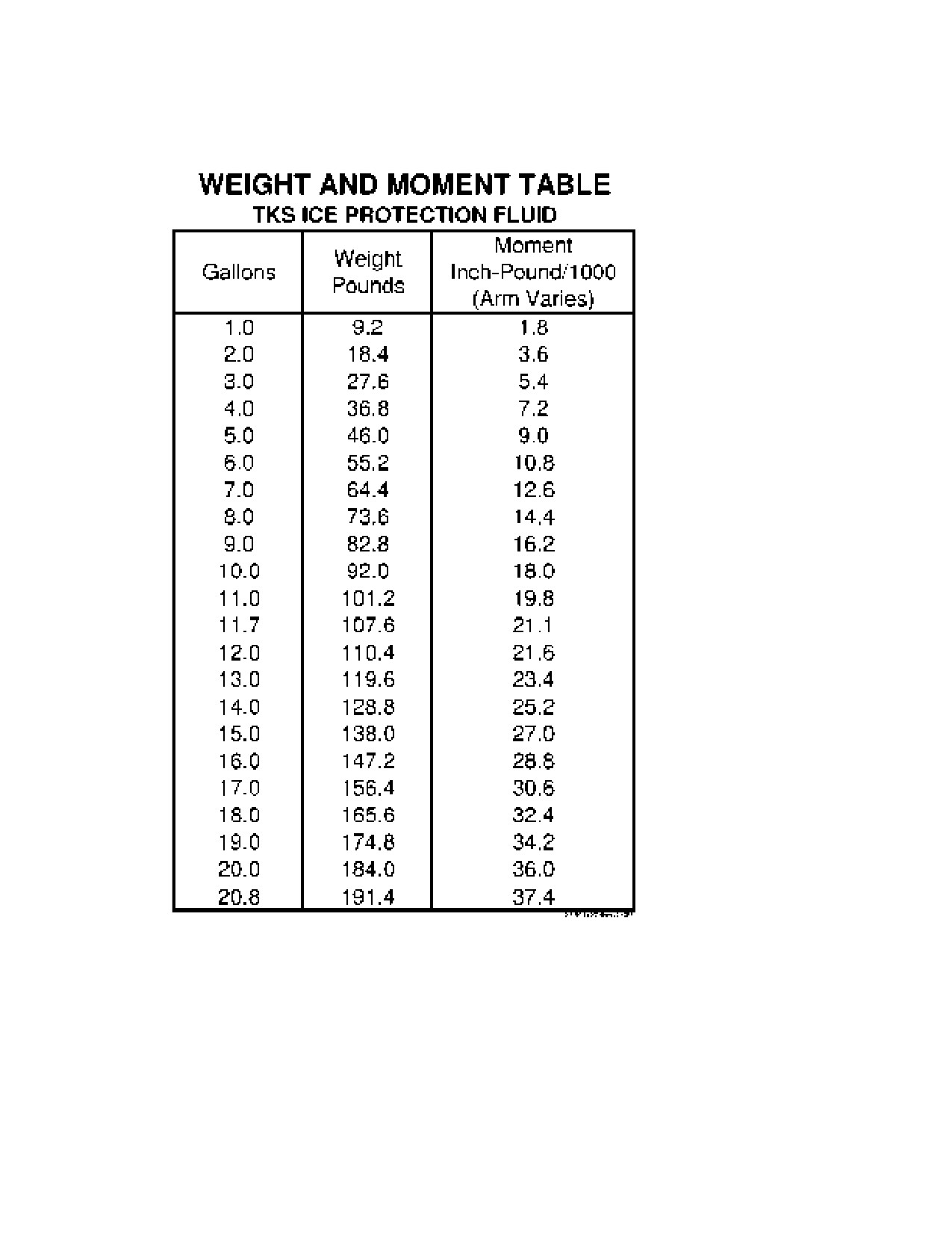
The 195.77 inch station reference for TKS is for the fluid
and tank installation and is not valid for computing the C.G.
for the TKS Zone.
Figure S1-2
FAA APPROVED
208BPHCUS-S1-00
U.S.
S1-53
SECTION 9 - SUPPLEMENTS
CESSNA
SUPPLEMENT 1
MODEL 208B 867 SHP
GARMIN G1000
WEIGHT AND BALANCE (Continued)
Figure S1-3
FAA APPROVED
S1-54
U.S.
208BPHCUS-S1-00
CESSNA
SECTION 9 - SUPPLEMENTS
MODEL 208B 867 SHP
SUPPLEMENT 1
GARMIN G1000
WEIGHT AND BALANCE (Continued)
WEIGHING PROCEDURES
1. In preparation to weighing and calculating the empty weight of
the TKS Ice Protection System equipped Cessna Caravan; the
TKS Ice Protection System must be drained of all fluid. Drain
fluid from tank through the drain valve on the left side of the tank
sump. When drained, no appreciable unusable fluid will remain
in the tank.
2. After draining all appreciable fluid from the tank, follow the
preparation and weighing instructions as specified in Section 6,
Weight and Balance of the POH/AFM.
FAA APPROVED
208BPHCUS-S1-00
U.S.
S1-55

SECTION 9 - SUPPLEMENTS
CESSNA
SUPPLEMENT 1
MODEL 208B 867 SHP
GARMIN G1000
WEIGHT AND BALANCE (Continued)
Figure S1-4 (Sheet 1 of 2)
FAA APPROVED
S1-56
U.S.
208BPHCUS-S1-00

CESSNA
SECTION 9 - SUPPLEMENTS
MODEL 208B 867 SHP
SUPPLEMENT 1
GARMIN G1000
WEIGHT AND BALANCE (Continued)
Figure S1-4 (Sheet 2)
FAA APPROVED
208BPHCUS-S1-00
U.S.
S1-57
SECTION 9 - SUPPLEMENTS
CESSNA
SUPPLEMENT 1
MODEL 208B 867 SHP
GARMIN G1000
AIRPLANE SYSTEMS AND DESCRIPTIONS
SYSTEM DESCRIPTION
The TKS Ice Protection System includes laser-drilled titanium porous
panels for the leading edges of the wings, horizontal and vertical
stabilizers, lift struts, propeller fluid slinger ring and windshield fluid
spray bar. Refer to Figures S1-5 and S1-6 for system installation and
fluid schematic.
The outer skin of the ice protection panels are manufactured with
titanium, which provides excellent strength, durability, light weight, and
corrosion resistance.
The panel skin is perforated by laser drilling holes, 0.0025 inches in
diameter, 800 per square inch. The porous areas of the titanium panels
are designed to assure fluid coverage from best rate of climb speed to
maximum operating speed.
The back plates of the panels are also manufactured out of titanium
and are formed to create reservoirs for the ice protection fluid, allowing
fluid supply to the entire porous area. A porous membrane between the
outer skin and the reservoir assure even flow and distribution through
the entire porous area of the panel.
The porous panels are bonded or attached as a cuff over a leading
edge. Panels are bonded to the airframe with a two-part, flexible
adhesive.
Fluid is supplied to the panels and propeller by two positive
displacement, constant volume metering pumps. The pumps provide
various flow rates to the panels and propeller. Single pump operation, a
combined mode, and timed pumping provide a range of flow rates for
different icing conditions.
Fluid for the windshield spray bar system is provided by an on-demand
gear pump. The spray bar may be activated as needed to clear forward
vision through the windshield.
(Continued Next Page)
FAA APPROVED
S1-58
U.S.
208BPHCUS-S1-00

CESSNA
SECTION 9 - SUPPLEMENTS
MODEL 208B 867 SHP
SUPPLEMENT 1
GARMIN G1000
AIRPLANE SYSTEMS AND DESCRIPTIONS (Continued)
SYSTEM DESCRIPTION (Continued)
TKS ICE PROTECTION SYSTEM INSTALLATION
Figure S1-5
(Continued Next Page)
FAA APPROVED
208BPHCUS-S1-00
U.S.
S1-59

SECTION 9 - SUPPLEMENTS
CESSNA
SUPPLEMENT 1
MODEL 208B 867 SHP
GARMIN G1000
AIRPLANE SYSTEMS AND DESCRIPTIONS (Continued)
TKS ICE PROTECTION SYSTEM FLUID SCHEMATIC
Figure S1-6
FAA APPROVED
S1-60
U.S.
208BPHCUS-S1-00
CESSNA
SECTION 9 - SUPPLEMENTS
MODEL 208B 867 SHP
SUPPLEMENT 1
GARMIN G1000
AIRPLANE SYSTEMS AND DESCRIPTIONS (Continued)
SYSTEM DESCRIPTION (Continued)
The fluid passes through microfilters prior to distribution to the porous
panels and propeller. The filter assures all contaminants are removed
from the fluid and prevents panel blockage.
A system of nylon tubing carries the fluid to proportioning units located
in the wings and tail of the airplane. The proportioning units divide the
flow into the volumetric requirements of each panel or device supplied
through the unit. Each panel and device is fed again with nylon tubing.
The TKS Ice Protection System tank is located in the cargo pod and
serviced through a single filler located on the left side of the pod, near
the left main landing gear. The tank has a maximum capacity of 20.8
gallons (78.7 l). It is the pilot’s responsibility to make sure that an
adequate quantity of TKS fluid is carried for the planned mission. A
minimum of 11.7 gallons (44.3 l) in the tank is required before takeoff if
the system is to be considered operational for dispatch into known icing
conditions. This minimum dispatch quantity must be determined by
visual inspection of the sight gage located on the filler end of the TKS
fluid tank, refer to Figure S1-10.
CAUTION
The sight gage is the only approved means of assuring
adequate fluid quantity prior to flight into known or
forecast icing conditions. The fluid level ball must be
above the minimum dispatch quantity line,11.7 U.S.
Gallons, (44.3 l) with the airplane level to make sure
proper indication.
The TKS fluid quantity is also measured by a sensor which transmits an
electrical signal to the level indicator. The fluid quantity indicator gage is
displayed on the MFD, refer to Figure S1-9.
(Continued Next Page)
FAA APPROVED
208BPHCUS-S1-00
U.S.
S1-61
SECTION 9 - SUPPLEMENTS
CESSNA
SUPPLEMENT 1
MODEL 208B 867 SHP
GARMIN G1000
AIRPLANE SYSTEMS AND DESCRIPTIONS (Continued)
SYSTEM DESCRIPTION (Continued)
The EIS strip on the MFD displays TKS (anti-ice) fluid quantity and time
remaining feature to aid the pilot as to the amount of fluid/time available
for ice protection. The system uses a series of colors to alert the pilot
as to how much time is remaining based on fluid quantity and ANTI-ICE
FLUID CONTROL switch position. Green readout informs the pilot of at
least 20 minutes of ice protection with the PRIMARY switch in NORM; 8
minutes with the PRIMARY switch in HIGH.
ANTI-ICE fluid quantity and time values displayed against an amber
background with black text alerts the pilot of less than 20 minutes of ice
protection with the PRIMARY switch in NORM; less than 8 minutes with
the PRIMARY switch in HIGH.
ANTI-ICE fluid quantity and time values displayed against a Red/White
(reverse video) background alerts the pilot of less than 0.5 gallon of
fluid. That equates to 5 minutes of ice protection with the PRIMARY
switch in NORM; less than 2 minutes with the PRIMARY switch in
HIGH.
When BACKUP is selected, the time remaining function is unreliable
and must not be used.
A wing inspection light, controlled by the WING LIGHT switch, is
provided to illuminate the leading edge of the left wing during night
operation.
FAA APPROVED
S1-62
U.S.
208BPHCUS-S1-00
CESSNA
SECTION 9 - SUPPLEMENTS
MODEL 208B 867 SHP
SUPPLEMENT 1
GARMIN G1000
AIRPLANE SYSTEMS AND DESCRIPTIONS (Continued)
TKS ICE PROTECTION SYSTEM OPERATION,
INDICATION AND MESSAGING
The TKS Ice Protection system is operated with three toggle switches.
These switches are located in the ANTI-ICE section of the lower left
pilot’s instrument panel, refer to Figure S1-7. Control of the TKS Ice
Protection System, ice detection light, pitot/static, Low Airspeed
Awareness, and stall vane heat are included in this row of switches.
Primary control of the system is accomplished through three switches
labeled PRIMARY, MAX FLOW, and BACKUP. These switches activate
the primary modes of ice protection, including Normal (NORM) and
HIGH, Maximum (MAX FLOW AIRFRAME) and WINDSHIELD, and
BACKUP, refer to Detail A of Figure S1-7.
Normal mode is activated by selecting the NORM position (center) on
the PRIMARY mode switch. NORM mode is the lowest fluid flow rate of
the system. The flow rate is achieved by running both metering pumps
of the system on a continuous repeat cycle of operation. The two
pumps will run for approximately 20 seconds, then deactivate. After 100
seconds of inactivity, the pumps will again activate for the 20 second
operation period. This on-off cycle of operation will continue until OFF
is selected on the PRIMARY mode switch.
HIGH mode is activated by selecting HIGH (up) on the PRIMARY mode
switch. HIGH mode is achieved by running one metering pump
continuously. Like NORM mode, the HIGH mode may be terminated by
selecting OFF on the PRIMARY mode switch.
Maximum flow (MAX FLOW) mode is provided for combating heavy or
extreme icing conditions. For MAX FLOW mode to operate, the
PRIMARY switch must be in either NORM or HIGH. With either of these
modes operating, MAX FLOW mode may be activated by selecting the
AIRFRAME position (spring-loaded up) on the MAX FLOW switch. The
MAX FLOW switch is spring-loaded and will immediately return to the
center position.
(Continued Next Page)
FAA APPROVED
208BPHCUS-S1-00
U.S.
S1-63
SECTION 9 - SUPPLEMENTS
CESSNA
SUPPLEMENT 1
MODEL 208B 867 SHP
GARMIN G1000
AIRPLANE SYSTEMS AND DESCRIPTIONS (Continued)
TKS ICE PROTECTION SYSTEM OPERATION,
INDICATION AND MESSAGING (Continued)
Activation of MAX FLOW AIRFRAME mode will run both metering
pumps continuously for a period of two minutes. At the end of two
minutes, the system will return to the mode of operation selected with
the PRIMARY mode switch. MAX FLOW mode will terminate operation
after:
1. The timer turns the mode OFF after two minutes, or
2. The PRIMARY mode switch is selected to OFF.
CAUTION
Each two minute use of MAX FLOW AIRFRAME mode
consumes approximately one gallon of ice protection
fluid, representing 5% of the total fluid capacity of the
ice protection system. Use MAX FLOW AIRFRAME
mode only when in heavy or extreme icing conditions. If
conditions require MAX FLOW AIRFRAME use, exit the
icing conditions immediately.
The windshield system may be activated by selecting the
WINDSHIELD position
(spring-loaded down) on the MAX FLOW
switch. The MAX FLOW switch is spring-loaded and will immediately
return to the center position. The windshield pump will run for
approximately four seconds after release of the switch. If the MAX
FLOW switch is continuously held in the WINDSHIELD position, the
windshield pump will continue to run when held down and four seconds
after the switch is released.
The windshield de-icing system is designed for intermittent operation to
establish pilot's forward vision as conditions require. The timer interval
is designed to provide an optimum burst of fluid for clearing the
windshield of ice. Momentary selection and release of the
WINDSHIELD switch will achieve the desired result.
(Continued Next Page)
FAA APPROVED
S1-64
U.S.
208BPHCUS-S1-00

CESSNA
SECTION 9 - SUPPLEMENTS
MODEL 208B 867 SHP
SUPPLEMENT 1
GARMIN G1000
TKS ICE PROTECTION SYSTEM OPERATION,
INDICATION AND MESSAGING
Figure S1-7
FAA APPROVED
208BPHCUS-S1-00
U.S.
S1-65
SECTION 9 - SUPPLEMENTS
CESSNA
SUPPLEMENT 1
MODEL 208B 867 SHP
GARMIN G1000
AIRPLANE SYSTEMS AND DESCRIPTIONS (Continued)
TKS ICE PROTECTION SYSTEM OPERATION,
INDICATION AND MESSAGING (Continued)
WARNING
The windshield pump is rated for intermittent use
only. Continuous operation may damage the pump.
Do not operate the WINDSHIELD position of the
MAX FLOW switch continuously longer than 6
seconds. Allow at least a total of
10 seconds
between operations.
The final operational mode of the system is the BACKUP mode.
BACKUP mode is achieved by selecting the ON position (up) on the
BACKUP switch. BACKUP mode activates the second metering pump
(opposite of the pump used in HIGH mode) and runs continuously like
HIGH mode. BACKUP mode is independent and isolated from the
other ice protection operational modes. It is provided as a redundant
capability in the event the normal operational modes are rendered
inoperable.
If BACKUP mode is selected in flight as prescribed in the Emergency
Procedures of this supplement, then the PRIMARY Switch should be
set to the OFF position, and the PRI ANTI-ICE circuit breaker pulled to
deactivate the PRIMARY system.
CAUTION
Other than the prescribed preflight steps outlined in the
Normal Procedures of this supplement, BACKUP mode
should never be used during normal operations. It is
intended for emergency use only (as detailed in the
Emergency Procedures of this supplement). When
operating the TKS Ice Protection System under normal
procedures, assure that the BACKUP Switch is
selected to OFF.
(Continued Next Page)
FAA APPROVED
S1-66
U.S.
208BPHCUS-S1-00

CESSNA
SECTION 9 - SUPPLEMENTS
MODEL 208B 867 SHP
SUPPLEMENT 1
GARMIN G1000
AIRPLANE SYSTEMS AND DESCRIPTIONS (Continued)
TKS ICE PROTECTION SYSTEM OPERATION,
INDICATION AND MESSAGING
(Continued)
For the four modes of airframe ice protection operation, the resulting
endurance with a full tank of fluid is:
MAXIMUM FLUID ENDURANCE
PRIMARY NORM selected
3 hours, 25 minutes
PRIMARY HIGH selected
1 hour, 20 minutes
BACKUP selected
1 hour, 20 minutes
MAX FLOW AIRFRAME selected
40 minutes
SYSTEMS ENDURANCE CHARACTERISTICS
Figure S1-8
FAA APPROVED
208BPHCUS-S1-00
U.S.
S1-67

SECTION 9 - SUPPLEMENTS
CESSNA
SUPPLEMENT 1
MODEL 208B 867 SHP
GARMIN G1000
AIRPLANE SYSTEMS AND DESCRIPTIONS (Continued)
TKS ICE PROTECTION SYSTEM OPERATION,
INDICATION AND MESSAGING (Continued)
SYSTEM FLUID QUANTITY INDICATIONS
Figure S1-9
As stated earlier, the only approved means for determining the proper
fluid quantity for dispatch into known icing conditions is the tank sight
gage. The sight gage is located on the left side of the fluid tank, near
the filler assembly. As illustrated in Figure S1-10, the sight gage may be
viewed through the cargo pod door located ahead of the filler.
To assure the minimum dispatch quantity is achieved, specific steps
must be taken. First, the airplane must be sitting in a wings level
attitude. If the airplane rests on a slope, the nose must be pointed up or
down the slope. Second, the volume of fluid in the tank must be such
that the bottom of the fluid ball is above the minimum dispatch line.
When both conditions have been met, the tank contains the minimum
quantity of fluid for flight into known icing.
(Continued Next Page)
FAA APPROVED
S1-68
U.S.
208BPHCUS-S1-00

CESSNA
SECTION 9 - SUPPLEMENTS
MODEL 208B 867 SHP
SUPPLEMENT 1
GARMIN G1000
AIRPLANE SYSTEMS AND DESCRIPTION (Continued)
TKS ICE PROTECTION SYSTEM OPERATION,
INDICATION AND MESSAGING (Continued)
FLUID TANK SIGHT GAGE
Figure S1-10
(Continued Next Page)
FAA APPROVED
208BPHCUS-S1-00
U.S.
S1-69
SECTION 9 - SUPPLEMENTS
CESSNA
SUPPLEMENT 1
MODEL 208B 867 SHP
GARMIN G1000
AIRPLANE SYSTEMS AND DESCRIPTIONS (Continued)
TKS ICE PROTECTION SYSTEM OPERATION,
INDICATION AND MESSAGING (Continued)
The operational state of the TKS ice protection system may be
monitored within the pilot’s and copilot’s PFD in the G1000 system.
System status is constantly monitored and feedback is provided
through various annunciations displayed in the annunciator window,
located to the right of the vertical speed tape of each pilot’s PFD, refer
to Figure S1-11.
TKS SYSTEM ANNUNCIATIONS
Figure S1-11
When the system is turned on using the PRIMARY mode switch, by
selecting either NORM or HIGH the white A-ICE NORM or white A-ICE
HIGH advisory message appears in the annunciation window. The
appropriate white message, A-ICE NORM or A-ICE HIGH, will remain
displayed independent of system operational conditions or status. The
advisory message is not active in the BACKUP mode.
The amber A-ICE PRESS HI annunciator is triggered by the high
pressure sensor located on the system equipment/tank assembly. If the
amber A-ICE PRESS HI annunciator is triggered, the system fluid filters
should be replaced.
Activation of the amber A-ICE FLUID LO annunciator means a low fluid
level condition exists and that at least 20 minutes of ice protection fluid
endurance remains when the system is operated in NORM mode.
(Continued Next Page)
FAA APPROVED
S1-70
U.S.
208BPHCUS-S1-00
CESSNA
SECTION 9 - SUPPLEMENTS
MODEL 208B 867 SHP
SUPPLEMENT 1
GARMIN G1000
AIRPLANE SYSTEMS AND DESCRIPTIONS (Continued)
TKS ICE PROTECTION SYSTEM OPERATION,
INDICATION AND MESSAGING (Continued)
NOTE
When the amber A-ICE FLUID LO annunciator comes ON
cross-check the anti-ice fluid quantity indication
(A-ICE
GAL) to verify a low fluid level condition exists. This system
is designed to trigger the annunciator when anti-ice fluid
quantity reaches two (2) U.S. gallons.
The red A-ICE PRESS LOW annunciator is tied to the two low pressure
sensors in the tail of the airplane. A low pressure condition on either
sensor will trigger the red A-ICE PRESS LOW annunciator, indicating
that system pressure is too low for normal system operation and may
be indicative of potential substandard ice protection performance.
In BACKUP mode, the red A-ICE PRESS LOW annunciator is armed
immediately upon selecting BACKUP ON. If a low pressure condition
exists, the red A-ICE PRESS LOW annunciator will display immediately
on both PFDs warning the crew to exit icing conditions immediately.
NOTE
With BACKUP selected ON, the red A-ICE PRESS LOW
annunciator will momentarily appear and remain ON until
system pressure is sufficient to inhibit the annunciator.
The red A-ICE PRESS LOW annunciator is inhibited for a period of
time in both PRIMARY modes of NORM and HIGH. When HIGH is
selected, any red A-ICE PRESS LOW annunciator will be inhibited for
15 seconds. After the 15 second period, any low pressure condition will
trigger the red A-ICE PRESS LOW annunciator. Selecting PRIMARY
OFF will reset the CAS inhibiting functions.
(Continued Next Page)
FAA APPROVED
208BPHCUS-S1-00
U.S.
S1-71
SECTION 9 - SUPPLEMENTS
CESSNA
SUPPLEMENT 1
MODEL 208B 867 SHP
GARMIN G1000
AIRPLANE SYSTEMS AND DESCRIPTIONS (Continued)
TKS ICE PROTECTION SYSTEM OPERATION,
INDICATION AND MESSAGING (Continued)
Likewise, selecting NORM will also inhibit the red A-ICE PRESS LOW
annunciator for a
15 second period, but the signal inhibiting will
continue with the on-off cycling of the pump. When the pumps are
activated for their 20 second cycle ON, the red A-ICE PRESS LOW
annunciator will be inhibited. After 15 seconds of operation of both
pumps, any low pressure condition will trigger the red A-ICE PRESS
LOW annunciator. When the pumps turn off, the inhibiting circuit is
reset for the next on-off pump cycle of the NORM mode. If a low
pressure condition exists, the operator will see periodic triggering of the
red A-ICE PRESS LOW annunciator for approximately 6 seconds every
2 minutes.
Inhibiting the red A-ICE PRESS LOW annunciator in HIGH and NORM
modes has been implemented to avoid nuisance CAS alerts.
PITOT/STATIC HEAT SYSTEMS
A left and right pitot-static heat system is installed to assure proper
airspeed indications in the event icing conditions are encountered. The
system is designed to prevent ice formation rather than remove it. The
pitot-static heat system consists of a heating element in each pitot-
static tube, a two-position toggle switch, labeled P/S HEAT/LOW A/S
AWARE, on the ANTI-ICE switch panel, and two pull-off type circuit
breakers, labeled LEFT PITOT HEAT and RIGHT PITOT HEAT, on the
left sidewall switch and circuit breaker panel. When the P/S HEAT/LOW
A/S AWARE switch is turned on, elements in both pitot-static tubes are
heated electrically to maintain proper operation in icing conditions.
Both pitot and static systems are monitored by the G1000 system for
insufficient current and alerting is provided to the flight crew by a single
chime and an amber L P/S HEAT, R P/S HEAT, or L-R P/S HEAT
annunciation.
(Continued Next Page)
FAA APPROVED
S1-72
U.S.
208BPHCUS-S1-00
CESSNA
SECTION 9 - SUPPLEMENTS
MODEL 208B 867 SHP
SUPPLEMENT 1
GARMIN G1000
AIRPLANE SYSTEMS AND DESCRIPTIONS (Continued)
LOW AIRSPEED AWARENESS SYSTEM
The Low Airspeed Awareness (LAA) system is designed to warn the
pilot when airspeed falls below 97.5 + 2.2 knots while operating in icing
conditions. The system consists of an annunciator with a white or
amber background and black letters, which reads BELOW ICING MIN
SPD.
LAA ANNUNCIATOR
Figure S1-12
This annunciator is mounted in the instrument panel directly in front of
the pilot, and is activated by an airspeed switch plumbed off the pilot’s
pitot and static lines. A remote mounted relay box provides logic for the
annunciator, and for the stall warning horn, which provides an aural
alert. Power is supplied from the LEFT PITOT HEAT and RIGHT PITOT
HEAT Circuit Breakers and through the P/S HEAT/LOW A/S AWARE
Switch. This switch has two positions, ON and OFF and the Low
Airspeed Awareness System is powered only when the P/S HEAT/
LOW A/S AWARE switch is ON and at least one of the two circuit
breakers is IN.
(Continued Next Page)
FAA APPROVED
208BPHCUS-S1-00
U.S.
S1-73
SECTION 9 - SUPPLEMENTS
CESSNA
SUPPLEMENT 1
MODEL 208B 867 SHP
GARMIN G1000
AIRPLANE SYSTEMS AND DESCRIPTIONS (Continued)
LOW AIRSPEED AWARENESS SYSTEM (Continued)
When the P/S HEAT/LOW A/S AWARE switch is turned ON prior to
takeoff, the BELOW ICING MIN SPD annunciator will be illuminated
white, indicating that the airspeed is below 97.5 + 2.2 knots. Once the
airspeed exceeds 97.5 + 2.2 knots, the BELOW ICING MIN SPD
annunciator will extinguish. If the airspeed falls back below 97.5 + 2.2
knots, the BELOW ICING MIN SPD annunciator will flash between
amber and white and the stall warning horn will sound intermittently
until the airspeed is increased above 97.5 + 2.2 knots.
Pressing the flashing BELOW ICING MIN SPD annunciator, which
incorporates a momentary switch, silences the stall warning horn and
causes the annunciator to stop flashing. The annunciator will remain
illuminated solid white as long as the airspeed is below 97.5 + 2.2
knots. The autopilot must be disengaged when the flashing amber and
white annunciation is activated.
The BELOW ICING MIN SPD annunciator brightness is controlled by
the LED PANELS/ANNUN rheostat located on the lower part of the
instrument panel to the left of the control pedestal. For daytime
operations the rheostat should be rotated full counter-clockwise to the
DAY position to make sure it is visible in bright light conditions. For all
other lighting conditions, the LED PANELS/ANNUN rheostat can be
adjusted clockwise to control lighting intensity.
FAA APPROVED
S1-74
U.S.
208BPHCUS-S1-00
CESSNA
SECTION 9 - SUPPLEMENTS
MODEL 208B 867 SHP
SUPPLEMENT 1
GARMIN G1000
AIRPLANE SYSTEMS AND DESCRIPTIONS (Continued)
ICE DETECTION AND WING INSPECTION LIGHTS
The windshield ice detection and wing inspection lights are used at
night, or in conditions of poor visibility, to detect the presence of ice
accumulating on the lower center portion of the windshield and leading
edge of the left wing.
The windshield ice detection light is located on the left side of the
windshield center post. This light would typically be used first to visually
detect the presence of ice accumulating on the windshield. The
windshield ice detection light is activated anytime the NAV Switch is in
the ON position.
The wing inspection light is flush-mounted in the left wing leading edge-
to-fuselage fairing to help detect ice on the wing at night by lighting the
leading edge of the wing. The system consists of the wing inspection
light, a two-position toggle switch located on the anti-ice switch panel
and a pull-off type circuit breaker, labeled WING ICE DET LIGHT,
located on the left sidewall circuit breaker panel. The WING LIGHT
switch is spring-loaded to the OFF, or down position, and must be held
in the ON or up position to activate the light.
ENGINE INERTIAL SEPARATOR, STANDBY ELECTRICAL,
AND HEATED STALL WARNING SYSTEMS
Refer to Section 7, Airplane and System Description of the POH/AFM
for descriptions of these standard/required equipment items.
FAA APPROVED
208BPHCUS-S1-00
U.S.
S1-75
SECTION 9 - SUPPLEMENTS
CESSNA
SUPPLEMENT 1
MODEL 208B 867 SHP
GARMIN G1000
HANDLING, SERVICING, AND MAINTENANCE
PROLONGED OUT OF SERVICE CARE
DURING FLYABLE STORAGE
Make sure that the TKS fluid tank contains at least the minimum takeoff
quantity of fluid and that all system components are filled with fluid.
Refer to Limitations, Minimum Dispatch Fluid, of this supplement for
minimum takeoff fluid quantity. Monthly, operate pump(s) until all air is
purged from components and pipelines. Check and/or refill the TKS
fluid tank to the minimum dispatch fluid level for takeoff.
SERVICING
ICE PROTECTION FLUID TANK
Refer to Limitations, Approved Ice Protection Fluid, in this supplement
for a list of approved TKS ice protection fluid type. The filler cap is
located on the left side of the cargo pod. To prevent the possibility of
contaminated fluid, always clean the top of fluid containers before
dispensing, and if required maintain a clean measuring vessel solely for
ice protection fluid. Secure the filler cap immediately after filling. Tank
vents are included in the pallet.
ICE PROTECTION FLUID STRAINER
The ice protection fluid strainers of the metering pumps should not
require cleaning unless there is a definite indication of foreign matter in
the TKS fluid tank.
ICE PROTECTION FLUID FILTERS
An amber A-ICE HIGH PRESS annunciator in flight, or during ground
testing, may indicate the need for filter element replacement.
(Continued Next Page)
FAA APPROVED
S1-76
U.S.
208BPHCUS-S1-00
CESSNA
SECTION 9 - SUPPLEMENTS
MODEL 208B 867 SHP
SUPPLEMENT 1
GARMIN G1000
HANDLING, SERVICING, AND MAINTENANCE
(Continued)
SERVICING (Continued)
POROUS LEADING EDGE PANEL CLEANING
CAUTION
Porous panels contain a plastic membrane which may
be damaged by certain solvents, particularly Methyl
Ethyl Ketone, Lacquer thinner and other types of
thinners. Mask panels when painting airplane or when
using solvents for other purposes in the proximity of the
porous panels. Refer to the Maintenance Manual for
detailed information on cleaning/painting interior and
exterior painted surfaces on the airplane.
Only the following fluids are approved for cleaning the TKS leading
edge porous panels.
1. Water (with soap or detergents)
2. Approved TKS Ice Protection System Fluids
3. Aviation Gasoline
4. Aviation Turbine Fuel
5. Isopropyl Alcohol
6. Ethyl Alcohol
7. Industrial Methylated Spirit
The porous panels may be washed with mild soap and water using a
brush or lint free cloth.
Refer to the Maintenance Manual for more detailed information on
handling, service, and maintenance.
FAA APPROVED
208BPHCUS-S1-00
U.S.
S1-77
SECTION 9 - SUPPLEMENTS
CESSNA
SUPPLEMENT 1
MODEL 208B 867 SHP
GARMIN G1000
This Page Intentionally Left Blank
FAA APPROVED
S1-78
U.S.
208BPHCUS-S1-00

CESSNA MODEL 208B
867 SHP - GARMIN G1000
Serials 208B2197 and 208B5000 and On
SUPPLEMENT 2
ARTEX ME406
EMERGENCY LOCATOR TRANSMITTER (ELT)
SERIAL NO.
REGISTRATION NO.
This supplement must be inserted into Section 9 of the Pilot's Operating Handbook
and FAA Approved Airplane Flight Manual when the Artex ME406 Emergency
Locator Transmitter (ELT) is installed.
19 DECEMBER 2012
COPYRIGHT © 2012
CESSNA AIRCRAFT COMPANY
WICHITA, KANSAS, USA
208BPHCUS-S2-00
U.S.
S2-1
SECTION 9 - SUPPLEMENTS
CESSNA
SUPPLEMENT 2
MODEL 208B 867 SHP
GARMIN G1000
SUPPLEMENT 2
ARTEX ME406 EMERGENCY LOCATOR TRANSMITTER
(ELT)
Use the Log of Effective Pages to determine the current status of this
supplement.
Pages affected by the current revision are indicated by an asterisk (*)
preceding the page number.
Supplement Status
Date
Original Issue
19 December 2012
LOG OF EFFECTIVE PAGES
Page
Page
Revision
Number
Status
Number
S2-1 thru S2-8
Original
0
FAA APPROVED
S2-2
U.S.
208BPHCUS-S2-00
CESSNA
SECTION 9 - SUPPLEMENTS
MODEL 208B 867 SHP
SUPPLEMENT 2
GARMIN G1000
SERVICE BULLETIN CONFIGURATION LIST
The following is a list of Service Bulletins that are applicable to the
operation of the airplane, and have been incorporated into this
supplement. This list contains only those Service Bulletins that are
currently active.
Airplane Serial
Revision
Incorporated
Number Title
Effectivity
Incorporated
in Airplane
FAA APPROVED
208BPHCUS-S2-00
U.S.
S2-3
SECTION 9 - SUPPLEMENTS
CESSNA
SUPPLEMENT 2
MODEL 208B 867 SHP
GARMIN G1000
ARTEX ME406 EMERGENCY LOCATOR
TRANSMITTER (ELT)
GENERAL
The Artex ME406 Emergency Locator Transmitter (ELT) installation
uses a solid-state
2-frequency transmitter powered by an internal
lithium battery. The ME406 is also equipped with an instrument panel-
mounted remote switch assembly, that includes a red warning light, and
an external antenna mounted on the top of the tailcone. The remote
switch assembly is installed along the upper right side of the instrument
panel and controls ELT operating modes from the flight crew station.
When the remote switch is set to the ARM position, the transmitter is
energized only when the internal G switch senses longitudinal inertia
forces per TSO-C91a/TSO-C126. When the remote switch is set to the
ON position, the transmitter is immediately energized.
The ME406 transmitter unit is located in the dorsal fin. On the ELT
transmitter unit is a panel containing an ARM/ON Switch and a
transmitter warning light.
The ELT installation uses two different warnings to tell the pilot when
the ELT is energized. The aural warning is an unusual buzzing sound
that is easily heard by the pilot. The visual warning is a flashing red light
directly above the remote switch that shows the pilot that the ELT has
been activated.
When the ME406 is energized, the ELT transmits the standard swept
tone signal on the international VHF frequency of 121.5 MHz until
battery power is gone. The 121.5 MHz signal is mainly used to pinpoint
the beacon during search and rescue operations, and is monitored by
general aviation, commercial aircraft, and government agencies.
In addition, for the first 24 hours of the ELT being energized, a 406.028
MHz signal is transmitted at 50 second intervals. This transmission
lasts 440 milliseconds and contains identification data programmed into
the ELT and is received by COSPAS/SARSAT satellites. The
transmitted data may include the Aircraft ID, ELT Serial Number,
Country Code, and COSPAS/SARSAT ID.
(Continued Next Page)
FAA APPROVED
S2-4
U.S.
208BPHCUS-S2-00

CESSNA
SECTION 9 - SUPPLEMENTS
MODEL 208B 867 SHP
SUPPLEMENT 2
GARMIN G1000
ARTEX ME406 ELT CONTROL PANEL
1.
ELT PANEL SWITCH (Two-Position Toggle Switch):
a. ARM
(OFF)
- Turns OFF and ARMS transmitter for
automatic activation if G switch senses a predetermined
deceleration level.
b. ON
- Activates transmitter instantly. The ON position
bypasses the automatic activation switch. The RED warning
light on ELT panel and on the remote switch assembly
mounted on the instrument panel should come on.
2.
TRANSMITTER WARNING LIGHT - Light comes on RED to
indicate the transmitter is transmitting a distress signal.
3.
ANTENNA RECEPTACLE - Connects to the antenna mounted
on top of tailcone.
4.
15-PIN D-SUB RECEPTACLE - Connects to the ELT remote
switch assembly located on the upper right side of the instrument
panel.
5.
REMOTE SWITCH ASSEMBLY - (Two-Position Rocker Switch):
a. ARM
(OFF)
- Turns OFF and ARMS transmitter for
automatic activation if G switch senses a predetermined
deceleration level.
b. ON
- Remotely activates the transmitter for test or
emergency situations. The RED warning light above the
rocker switch comes on to indicate that the transmitter is
transmitting a distress signal.
Figure S2-1
FAA APPROVED
208BPHCUS-S2-00
U.S.
S2-5
SECTION 9 - SUPPLEMENTS
CESSNA
SUPPLEMENT 2
MODEL 208B 867 SHP
GARMIN G1000
OPERATING LIMITATIONS
There are no additional airplane operating limitations when the Artex
ME406 ELT is installed.
The airplane owner or operator must register the ME406 ELT with the
applicable Civil Aviation Authority before use to make sure that the
identification code transmitted by the ELT is in the COSPAS/SARSAT
database. Refer to www.cospas-sarsat.org for registration information.
Refer to 14 CFR 91.207 for ELT inspection requirements. The ME406
must be inspected and tested by an approved technician using the
correct test equipment under the appropriate Civil Aviation Authorities
approved conditions.
FAA APPROVED
S2-6
U.S.
208BPHCUS-S2-00
CESSNA
SECTION 9 - SUPPLEMENTS
MODEL 208B 867 SHP
SUPPLEMENT 2
GARMIN G1000
EMERGENCY PROCEDURES
If a forced landing is necessary, set the remote switch to the ON
position before landing. This is very important in remote or
mountainous terrain. The red warning light above the remote switch will
flash and the aural warning will be heard.
After a landing when search and rescue aid is needed, use the ELT as
follows:
NOTE
The ELT remote switch assembly could be inoperative if
damaged during a forced landing. If inoperative, the inertia
G switch will activate automatically. However, to turn the
ELT OFF and ON again requires manual switching of the
ELT panel switch which is located on the ELT unit.
1.
MAKE SURE THE ELT IS ENERGIZED:
a. If the red warning light above the remote switch is not
flashing, set the remote switch to the ON position.
b. Listen for the aural warning. If the COM radio(s) operate and
can be energized safely (no threat of fire or explosion),
energize a COM radio and set the frequency to 121.5 MHz.
The ELT tone should be heard on the COM radio if the ELT
is working correctly. When done, de-energize the COM
radio(s) to conserve the airplane battery power.
c. Make sure that nothing is touching or blocking the ELT
antenna.
2.
AFTER RESCUE - Set the remote switch to the ARM position to
de-energize the ELT. If the remote switch does not function, set
the switch on the ME406 (in the dorsal fin) to the ARM position.
FAA APPROVED
208BPHCUS-S2-00
U.S.
S2-7
SECTION 9 - SUPPLEMENTS
CESSNA
SUPPLEMENT 2
MODEL 208B 867 SHP
GARMIN G1000
NORMAL PROCEDURES
When operating in a remote area or over hazardous terrain, it is
recommended that the ELT be inspected by an approved technician
more frequently than required by 14 CFR 91.207.
NORMAL OPERATION
1. Check that the remote switch (on the upper right instrument
panel) is set to the ARM position.
Normal operation of the ME406 from the co-pilot station is only to de-
energize and arm the ELT after it has been accidentally energized (no
emergency).
The ELT can be energized by a lightning strike or hard landing. If the
red light above the remote switch is flashing and the aural warning is
heard, the ELT is energized. Check for the emergency signal on a COM
radio set to 121.5 MHz. To stop the transmissions, set the remote
switch to the ON position momentarily and then set to the ARM
position. Tell the nearest Air Traffic Control facility about the accidental
transmissions as soon as possible to hold search and rescue work to a
minimum.
PERFORMANCE
There is no change to the airplane performance when the Artex ME406
ELT is installed.
FAA APPROVED
S2-8
U.S.
208BPHCUS-S2-00
CESSNA MODEL 208B
867 SHP - GARMIN G1000
Serials 208B2197 and 208B5000 and On
SUPPLEMENT 3
ARTEX C406-N
EMERGENCY LOCATOR TRANSMITTER (ELT)
SERIAL NO.
REGISTRATION NO.
This supplement must be inserted into Section 9 of the Pilot's Operating Handbook
and FAA Approved Airplane Flight Manual when the Artex C406-N Emergency
Locator Transmitter (ELT) is installed.
19 DECEMBER 2012
COPYRIGHT © 2012
CESSNA AIRCRAFT COMPANY
WICHITA, KANSAS, USA
208BPHCUS-S3-00
U.S.
S3-1
SECTION 9 - SUPPLEMENTS
CESSNA
SUPPLEMENT 3
MODEL 208B 867 SHP
GARMIN G1000
SUPPLEMENT 3
ARTEX C406-N EMERGENCY LOCATOR
TRANSMITTER (ELT)
Use the Log of Effective Pages to determine the current status of this
supplement.
Pages affected by the current revision are indicated by an asterisk (*)
preceding the page number.
Supplement Status
Date
Original Issue
19 December 2012
LOG OF EFFECTIVE PAGES
Page
Page
Revision
Number
Status
Number
S3-1 thru S3-8
Original
0
FAA APPROVED
S3-2
U.S.
208BPHCUS-S3-00
CESSNA
SECTION 9 - SUPPLEMENTS
MODEL 208B 867 SHP
SUPPLEMENT 3
GARMIN G1000
SERVICE BULLETIN CONFIGURATION LIST
The following is a list of Service Bulletins that are applicable to the
operation of the airplane, and have been incorporated into this
supplement. This list contains only those Service Bulletins that are
currently active.
Airplane Serial
Revision
Incorporated
Number Title
Effectivity
Incorporated
in Airplane
FAA APPROVED
208BPHCUS-S3-00
U.S.
S3-3
SECTION 9 - SUPPLEMENTS
CESSNA
SUPPLEMENT 3
MODEL 208B 867 SHP
GARMIN G1000
ARTEX C406-N EMERGENCY LOCATOR
TRANSMITTER (ELT)
GENERAL
The Artex C406-N Emergency Locator Transmitter (ELT) installation
uses a solid-state
3-frequency transmitter powered by an internal
lithium battery. The navigation function of the C406-N ELT receives
power from the airplane’s main battery thru AVIONICS BUS 1. The
C406-N is also equipped with an instrument panel-mounted remote
switch assembly, that includes a red warning light, and an external
antenna mounted on the top of the tailcone. The remote switch
assembly is installed along the upper right side of the instrument panel
and controls ELT operating modes from the flight crew station. When
the remote switch is set to the ARM position, the transmitter is
energized only when the internal G Switch senses longitudinal inertia
forces per TSO-C91a/TSO-C126. When the remote switch is set to the
ON position, the transmitter is immediately energized.
The C406-N transmitter unit is located in the dorsal fin (right side). On
the ELT transmitter unit is a panel containing an ON/OFF Switch and a
transmitter warning light.
The ELT installation uses two different warnings to tell the pilot when
the ELT is energized. The aural warning is an unusual buzzing sound
that is easily heard by the pilot. The visual warning is a flashing red light
directly above the remote switch that shows the pilot that the ELT has
been activated.
When the C406-N is energized, the ELT transmits the standard swept
tone signal on the international VHF frequency of 121.5 MHz and UHF
frequency of 243.0 MHz until battery power is gone. The 121.5 MHz
signal is mainly used to pinpoint the beacon during search and rescue
operations, and is monitored by general aviation, commercial aircraft,
and government agencies.
In addition, for the first 24 hours of the ELT being energized, a 406.028
MHz signal is transmitted at 50 second intervals. This transmission
lasts 440 milliseconds and contains identification data programmed into
the ELT and is received by COSPAS/SARSAT satellites. The
transmitted data may include the Aircraft ID, GPS coordinates, ELT
Serial Number, Country Code, and COSPAS/SARSAT ID.
(Continued Next Page)
FAA APPROVED
S3-4
U.S.
208BPHCUS-S3-00

CESSNA
SECTION 9 - SUPPLEMENTS
MODEL 208B 867 SHP
SUPPLEMENT 3
GARMIN G1000
ARTEX C406-N ELT CONTROL PANEL
1.
ELT PANEL SWITCH (Two-Position Toggle Switch):
a. ARM
(OFF)
- Turns OFF and ARMS transmitter for
automatic activation if G Switch senses a predetermined
deceleration level.
b. ON
- Activates transmitter instantly. The ON position
bypasses the automatic activation switch. The RED
warning light on ELT panel and on the remote switch
assembly mounted on the instrument panel should come
on.
2.
TRANSMITTER WARNING LIGHT - Light comes on RED to
indicate the transmitter is transmitting a distress signal.
3.
ANTENNA RECEPTACLE - Connects to the antenna mounted
on top of tailcone.
4.
REMOTE CABLE JACK - Connects to the ELT remote switch
assembly located on the upper right side of the instrument panel.
5.
REMOTE SWITCH ASSEMBLY - (Two-Position Rocker Switch):
a. ARM
(OFF)
- Turns OFF and ARMS transmitter for
automatic activation if G Switch senses a predetermined
deceleration level.
b. ON
- Remotely activates the transmitter for test or
emergency situations. The RED warning light above the
rocker switch comes on to indicate that the transmitter is
transmitting a distress signal.
Figure S3-1
FAA APPROVED
208BPHCUS-S3-00
U.S.
S3-5
SECTION 9 - SUPPLEMENTS
CESSNA
SUPPLEMENT 3
MODEL 208B 867 SHP
GARMIN G1000
OPERATING LIMITATIONS
There are no additional airplane operating limitations when the Artex
C406-N ELT is installed.
The airplane owner or operator must register the C406-N ELT with the
applicable Civil Aviation Authority before use to make sure that the
identification code transmitted by the ELT is in the COSPAS/SARSAT
database. Refer to www.cospas-sarsat.org for registration information.
Refer to 14 CFR 91.207 for ELT inspection requirements. The C406-N
must be inspected and tested by an approved technician using the
correct test equipment under the appropriate Civil Aviation Authorities
approved conditions.
FAA APPROVED
S3-6
U.S.
208BPHCUS-S3-00
CESSNA
SECTION 9 - SUPPLEMENTS
MODEL 208B 867 SHP
SUPPLEMENT 3
GARMIN G1000
EMERGENCY PROCEDURES
If a forced landing is necessary, set the remote switch to the ON
position before landing. This is very important in remote or
mountainous terrain. The red warning light above the remote switch will
flash and the aural warning will be heard.
After a landing when search and rescue aid is needed, use the ELT as
follows:
NOTE
The ELT remote switch assembly could be inoperative if
damaged during a forced landing. If inoperative, the inertia
G Switch will activate automatically. However, to turn the
ELT OFF and ON again requires manual switching of the
ELT panel switch which is located on the ELT unit.
1. MAKE SURE THE ELT IS ENERGIZED:
a. If the red warning light above the remote switch is not
flashing, set the remote switch to the ON position.
b. Listen for the aural warning. If the COM radio(s) operate and
can be energized safely (no threat of fire or explosion),
energize a COM radio and set the frequency to 121.5 MHz.
The ELT tone should be heard on the COM radio if the ELT
is working correctly. When done, de-energize the COM
radio(s) to conserve the airplane battery power.
c. Make sure that nothing is touching or blocking the ELT
antenna.
2. AFTER RESCUE - Set the remote switch to the ARM position to
de-energize the ELT. If the remote switch does not function, set
the switch on the C406-N (in the dorsal fin) to the ARM position.
FAA APPROVED
208BPHCUS-S3-00
U.S.
S3-7
SECTION 9 - SUPPLEMENTS
CESSNA
SUPPLEMENT 3
MODEL 208B 867 SHP
GARMIN G1000
NORMAL PROCEDURES
When operating in a remote area or over hazardous terrain, it is
recommended that the ELT be inspected by an approved technician
more frequently than required by 14 CFR 91.207.
NORMAL OPERATION
1. Check that the remote switch (on the upper right instrument
panel) is set to the ARM position.
Normal operation of the C406-N from the co-pilot station is only to
de-energize and arm the ELT after it has been accidentally energized
(no emergency).
The ELT can be energized by a lightning strike or hard landing. If the
red light above the remote switch is flashing and the aural warning is
heard, the ELT is energized. Check for the emergency signal on a COM
radio set to 121.5 MHz. To stop the transmissions, set the remote
switch to the ON position momentarily and then set to the ARM
position. Tell the nearest Air Traffic Control facility about the accidental
transmissions as soon as possible to hold search and rescue work to a
minimum.
PERFORMANCE
There is no change to the airplane performance when the Artex
C406-N ELT is installed.
FAA APPROVED
S3-8
U.S.
208BPHCUS-S3-00

CESSNA MODEL 208B
867 SHP - GARMIN G1000
Serials 208B2197 and 208B5000 and On
SUPPLEMENT 4
GARMIN G1000
SYNTHETIC VISION TECHNOLOGY (SVT)
SERIAL NO.
REGISTRATION NO.
This supplement must be inserted into Section 9 of the Pilot's Operating Handbook
and FAA Approved Airplane Flight Manual when the Garmin G1000 Synthetic
Vision Technology (SVT) is installed.
19 DECEMBER 2012
COPYRIGHT © 2012
CESSNA AIRCRAFT COMPANY
WICHITA, KANSAS, USA
208BPHCUS-S4-00
U.S.
S4-1
SECTION 9 - SUPPLEMENTS
CESSNA
SUPPLEMENT 4
MODEL 208B 867 SHP
GARMIN G1000
SUPPLEMENT 4
GARMIN G1000 SYNTHETIC VISION TECHNOLOGY
Use the Log of Effective Pages to determine the current status of this
supplement.
Pages affected by the current revision are indicated by an asterisk (*)
preceding the page number.
Supplement Status
Date
Original Issue
19 December 2012
LOG OF EFFECTIVE PAGES
Page
Page
Revision
Number
Status
Number
S4-1 thru S4-6
Original
0
FAA APPROVED
S4-2
U.S.
208BPHCUS-S4-00
CESSNA
SECTION 9 - SUPPLEMENTS
MODEL 208B 867 SHP
SUPPLEMENT 4
GARMIN G1000
SERVICE BULLETIN CONFIGURATION LIST
The following is a list of Service Bulletins that are applicable to the
operation of the airplane, and have been incorporated into this
supplement. This list contains only those Service Bulletins that are
currently active.
Airplane Serial
Revision
Incorporated
Number Title
Effectivity
Incorporated
in Airplane
FAA APPROVED
208BPHCUS-S4-00
U.S.
S4-3
SECTION 9 - SUPPLEMENTS
CESSNA
SUPPLEMENT 4
MODEL 208B 867 SHP
GARMIN G1000
GARMIN G1000 SYNTHETIC VISION TECHNOLOGY
GENERAL
The Garmin G1000 Synthetic Vision Technology (SVT) is primarily
composed of a computer-generated, forward looking attitude aligned
view of the topography immediately in front of the airplane from the
pilot’s perspective. The SVT information is shown on the Primary Flight
Display
(PFD) and offers a three dimensional view of potentially
hazardous terrain, obstacles and traffic complete with the requisite red
or yellow shading overlaid. For complete system description and
operation, refer to the Garmin G1000 Cockpit Reference Guide (CRG).
NOTE
Not all airport runways are depicted with SVT.
OPERATING LIMITATIONS
The G1000 limitations listed in Section 2, of the POH apply when using
SVT. In addition, SVT is not available in locations north of 75° North
latitude or south of 60° South latitude due to the absence of terrain data
in these geographical areas.
Airplane maneuvering in any flight phase shall not be based solely on
information from the G1000 SVT. SVT shall not be used as the primary
means of terrain, obstacle or traffic avoidance.
The G1000 SVT shall not be used for primary flight guidance.
Descent below published IFR minimums shall not be predicated upon
the use of G1000 SVT.
The G1000 SVT Pathways are not a substitute for standard course and
altitude deviation information provided by the primary lateral and
vertical guidance.
(Continued Next Page)
FAA APPROVED
S4-4
U.S.
208BPHCUS-S4-00
CESSNA
SECTION 9 - SUPPLEMENTS
MODEL 208B 867 SHP
SUPPLEMENT 4
GARMIN G1000
OPERATING LIMITATIONS (Continued)
The following limitation applies only to EASA registered airplanes:
• The G1000 SVT Pathways shall not be used while the
Flight Director is in use. Pathways guidance must be
deselected to reduce PFD display clutter when the Flight
Director is displayed.
The current Garmin G1000 Cockpit Reference Guide Part number for
SVT that must be available to the pilot during flight is displayed on the
MFD AUX group, SYSTEM STATUS page.
EMERGENCY PROCEDURES
There is no change to the airplane emergency procedures when the
Garmin G1000 Synthetic Vision Technology is installed.
ABNORMAL PROCEDURES
G1000 SVT PATHWAYS MALFUNCTION OR ERRONEOUS
LATERAL AND/OR VERTICAL GUIDANCE
If G1000 SVT Pathways malfunctions or provides an erroneous
indication contrary to the primary lateral and vertical guidance, use the
following procedure to turn off SVT Pathways:
1. PFD Softkey
PRESS (on PFD bezel)
2. SYN VIS Softkey
PRESS (on PFD bezel)
3. Pathway Softkey
PRESS (on PFD bezel)
(verify SVT Pathway guidance is removed from the PFD display)
FAA APPROVED
208BPHCUS-S4-00
U.S.
S4-5
SECTION 9 - SUPPLEMENTS
CESSNA
SUPPLEMENT 4
MODEL 208B 867 SHP
GARMIN G1000
NORMAL PROCEDURES
There is no change to the airplane normal procedures when the Garmin
G1000 Synthetic Vision Technology is installed.
PERFORMANCE
There is no change to the airplane performance when the Garmin
G1000 Synthetic Vision Technology is installed.
WEIGHT AND BALANCE
There is no change to the airplane weight and balance when the
Garmin G1000 Synthetic Vision Technology is installed.
FAA APPROVED
S4-6
U.S.
208BPHCUS-S4-00

CESSNA MODEL 208B
867 SHP - GARMIN G1000
Serials 208B2197 and 208B5000 and On
SUPPLEMENT 5
CONFIGURATION DEVIATION LIST (CDL)
SERIAL NO.
REGISTRATION NO.
This supplement must be inserted into Section 9 of the Pilot's Operating Handbook
and FAA Approved Airplane Flight Manual.
19 DECEMBER 2012
COPYRIGHT © 2012
CESSNA AIRCRAFT COMPANY
WICHITA, KANSAS, USA
208BPHCUS-S5-00
U.S.
S5-1
SECTION 9 - SUPPLEMENTS
CESSNA
SUPPLEMENT 5
MODEL 208B 867 SHP
GARMIN G1000
SUPPLEMENT 5
CONFIGURATION DEVIATION LIST (CDL)
Use the Log of Effective Pages to determine the current status of this
supplement.
Pages affected by the current revision are indicated by an asterisk (*)
preceding the page number.
Supplement Status
Date
Original Issue
19 December 2012
LOG OF EFFECTIVE PAGES
Page
Page
Revision
Number
Status
Number
S5-1 thru S5-6
Original
0
FAA APPROVED
S5-2
U.S.
208BPHCUS-S5-00
CESSNA
SECTION 9 - SUPPLEMENTS
MODEL 208B 867 SHP
SUPPLEMENT 5
GARMIN G1000
SERVICE BULLETIN CONFIGURATION LIST
The following is a list of Service Bulletins that are applicable to the
operation of the airplane, and have been incorporated into this
supplement. This list contains only those Service Bulletins that are
currently active.
Airplane Serial
Revision
Incorporated
Number Title
Effectivity
Incorporated
in Airplane
FAA APPROVED
208BPHCUS-S5-00
U.S.
S5-3
SECTION 9 - SUPPLEMENTS
CESSNA
SUPPLEMENT 5
MODEL 208B 867 SHP
GARMIN G1000
CONFIGURATION DEVIATION LIST
GENERAL
This supplement is part of, and must be placed in, the Pilots Operating
Handbook and basic FAA Approved Airplane Flight Manual (POH/
AFM). The information contained herein supplements the information of
the POH/AFM. For limitations, procedures and performance
information not contained in this supplement, consult the POH/AFM.
This supplement, Configuration Deviation List
(CDL) contains
additional certification limitations for operations without secondary
airframe parts.
OPERATING LIMITATIONS
1.
When the airplane is operated using the CDL, it must be
operated in accordance with the limitations specified in the
POH/AFM, as amended in the CDL.
2.
The associated limitations must be listed on a placard affixed in
the cockpit in clear view of the pilot in command and other
appropriate crew member(s).
3.
The pilot in command must be notified of each operation with a
missing part(s) by listing the missing part(s) in the flight or
dispatch release. If a flight or dispatch release system is not
used, other appropriate means can be used to notify the pilot in
command.
4.
The operator must list in the airplane logbook an appropriate
notation covering the missing part(s).
5.
If an additional part is lost in flight, the airplane may not depart
the airport at which it landed following this event, until it again
complies with the limitations of the CDL. This, of course, does
not preclude the issuance of a ferry permit to allow the airplane
to be flown to a point where the necessary repairs or
replacements can be made.
6.
Flight into known or forecasted icing conditions is prohibited with
missing TKS Leading Edge Vortex Generator(s).
FAA APPROVED
S5-4
U.S.
208BPHCUS-S5-00
CESSNA
SECTION 9 - SUPPLEMENTS
MODEL 208B 867 SHP
SUPPLEMENT 5
GARMIN G1000
CONFIGURATION DEVIATION LIST
The numbering and designation of systems in the CDL appendix is
based on Air Transport Association (ATA) Specification Number 2200.
The parts within each system are identified by functional description
and, when necessary, by part numbers.
ATA
System or Unit
1. Number Installed
2. Number Required for Dispatch
Requirements for Flight
57
Wings
1. TKS Leading Edge
20
16
No more than two non-adjacent
Vortex Generators
vortex generators per wing may be
missing. Flight into known or forecast
icing is prohibited.*
* The performance decrement is negligible.
FAA APPROVED
208BPHCUS-S5-00
U.S.
S5-5
SECTION 9 - SUPPLEMENTS
CESSNA
SUPPLEMENT 5
MODEL 208B 867 SHP
GARMIN G1000
EMERGENCY PROCEDURES
There is no change to the airplane emergency procedures when
utilizing the Configuration Deviation List (CDL).
NORMAL PROCEDURES
There is no change to the airplane normal procedures when utilizing
the Configuration Deviation List (CDL).
PERFORMANCE
There is no change to the airplane performance when utilizing the
Configuration Deviation List (CDL).
WEIGHT AND BALANCE
There is no change to the airplane weight and balance when utilizing
the Configuration Deviation List (CDL).
FAA APPROVED
S5-6
U.S.
208BPHCUS-S5-00

CESSNA MODEL 208B
867 SHP - GARMIN G1000
Serials 208B2197 and 208B5000 and On
SUPPLEMENT 6
OXYGEN SYSTEM
SERIAL NO.
REGISTRATION NO.
This supplement must be inserted into Section 9 of the Pilot's Operating Handbook
and FAA Approved Airplane Flight Manual when the Oxygen System is installed.
19 DECEMBER 2012
COPYRIGHT © 2012
CESSNA AIRCRAFT COMPANY
WICHITA, KANSAS, USA
208BPHCUS-S6-00
U.S.
S6-1
SECTION 9 - SUPPLEMENTS
CESSNA
SUPPLEMENT 6
MODEL 208B 867 SHP
GARMIN G1000
SUPPLEMENT 6
OXYGEN SYSTEM
Use the Log of Effective Pages to determine the current status of this
supplement.
Pages affected by the current revision are indicated by an asterisk (*)
preceding the page number.
Supplement Status
Date
Original Issue
19 December 2012
LOG OF EFFECTIVE PAGES
Page
Page
Revision
Number
Status
Number
S6-1 thru S6-10
Original
0
FAA APPROVED
S6-2
U.S.
208BPHCUS-S6-00
CESSNA
SECTION 9 - SUPPLEMENTS
MODEL 208B 867 SHP
SUPPLEMENT 6
GARMIN G1000
SERVICE BULLETIN CONFIGURATION LIST
The following is a list of Service Bulletins that are applicable to the
operation of the airplane, and have been incorporated into this
supplement. This list contains only those Service Bulletins that are
currently active.
Airplane Serial
Revision
Incorporated
Number Title
Effectivity
Incorporated
in Airplane
FAA APPROVED
208BPHCUS-S6-00
U.S.
S6-3
SECTION 9 - SUPPLEMENTS
CESSNA
SUPPLEMENT 6
MODEL 208B 867 SHP
GARMIN G1000
OXYGEN SYSTEM
GENERAL
The oxygen system provides supplemental oxygen necessary for
continuous flight at high altitude. The oxygen system contains two ports
in the cockpit with either an extra 8 (10 total) or extra 15 (17 total) in the
cabin.
The small capacity oxygen cylinder of 51 cubic foot supplies oxygen to
the two-port system. The larger capacity oxygen cylinder of 117 cubic
foot supplies oxygen to the 10-port or 17-port system. The oxygen
cylinder is located in the fuselage tailcone. Cylinder pressure is
reduced to an operating pressure of 70 PSI by a pressure regulator
attached to the cylinder. A shutoff valve is included as part of the
regulator assembly. The system also contains an altitude compensating
regulator located between the pressure regulator and the oxygen
supply lines, which varies the flow of oxygen to the masks, depending
on altitude. An oxygen cylinder filler valve is located on the right side of
the airplane (under a cover plate), at the forward end of the tailcone.
Cylinder pressure is indicated by a pressure gage located on the
overhead console above the pilot’s and copilot’s seats. Two oxygen
outlets are provided in the cabin ceiling, one each just outboard of the
pilot’s and copilot’s seats. Two permanent microphone-equipped masks
are provided for the pilot and copilot. Both masks are the partial
rebreathing type equipped with vinyl plastic hoses and flow indicators.
The oxygen hoses are the high-flow type and are color coded with a
blue band adjacent to the plug-in fitting.
(Continued Next Page)
FAA APPROVED
S6-4
U.S.
208BPHCUS-S6-00
CESSNA
SECTION 9 - SUPPLEMENTS
MODEL 208B 867 SHP
SUPPLEMENT 6
GARMIN G1000
GENERAL (Continued)
NOTE
The pilot’s and copilot’s masks are equipped with a
microphone to facilitate use of the radio when using
oxygen. An adapter cord is furnished with the
microphone-equipped mask to mate the mask microphone
lead to the microphone jack located on the left or right side
of the instrument panel. To connect the oxygen mask
microphone, connect the mask lead to the adapter cord and
plug the cord into the microphone jack. If an optional
microphone-headset combination has been in use, the
microphone lead from this equipment is already plugged
into the microphone jack. It will be necessary to disconnect
this lead from the microphone jack so that the adapter cord
from the oxygen mask microphone can be plugged into the
jack. A push-to-talk switch is incorporated on each control
wheel to operate the corresponding microphone.
A remote OXYGEN control lever is located in the overhead console
above the pilot’s and copilot’s seats and is used to shutoff the supply of
oxygen to the system when not in use. The control lever is
mechanically connected to the shutoff valve at the cylinder. The
OXYGEN control lever is ON when the lever is in the full forward
position and OFF when in the full aft position. With the exception of the
shutoff function, the system is completely automatic and requires no
manual regulation for change of altitude.
The oxygen cylinder, when fully charged, contain either 51 or 117 cubic
feet of aviator’s breathing oxygen (Spec. No. MIL-O-27210) under a
pressure of 1960 PSI at 70°F (20°C). Filling pressures will vary due to
ambient temperature in the filling area and the temperature rise
resulting from compression of the oxygen. Filling to 1960 PSI may not
result in a properly filled cylinder. Fill to pressures indicated in Figure
S6-1, Oxygen Filling Pressures, for ambient temperatures.
(Continued Next Page)
FAA APPROVED
208BPHCUS-S6-00
U.S.
S6-5

SECTION 9 - SUPPLEMENTS
CESSNA
SUPPLEMENT 6
MODEL 208B 867 SHP
GARMIN G1000
GENERAL (Continued)
WARNING
Oil, grease, or other lubricants in contact with
oxygen create a serious fire hazard and such
contact must be avoided when handling oxygen
equipment.
OXYGEN FILLING PRESSURES
Figure S6-1
OPERATING LIMITATIONS
There are no additional airplane operating limitations when the Oxygen
System is installed.
EMERGENCY PROCEDURES
There is no change to the airplane emergency procedures when the
Oxygen System is installed.
FAA APPROVED
S6-6
U.S.
208BPHCUS-S6-00
CESSNA
SECTION 9 - SUPPLEMENTS
MODEL 208B 867 SHP
SUPPLEMENT 6
GARMIN G1000
NORMAL PROCEDURES
Prior to flight, check to be sure that there is an adequate oxygen supply
for the trip by noting the oxygen pressure gage reading and the
appropriate Oxygen Duration Chart for your airplane. Refer to Figure
S6-2 for the 51 cubic feet capacity bottle and Figure S6-3 for the larger
117 cubic feet bottle. Make sure that there are enough face masks and
hoses for each passenger and that they are readily accessible and in
good working condition.
The Oxygen Duration Chart should be used in determining the usable
duration (in hours) of the oxygen supply in your airplane. The following
procedure outlines the method of finding the duration from the chart.
1. Note the available oxygen bottle size and pressure shown on
the pressure gage.
2. Locate this pressure on the scale on the left side of the
appropriate chart, then go across the chart horizontally to the
right until you intersect the line representing the altitude at which
the flight will be conducted. After intersecting the line, drop down
vertically to the bottom of the chart and read the duration in
hours given on the scale. This duration is for one person only
and will have to be divided by the number of persons using
oxygen to obtain the total duration in hours.
3. As an example of the above procedure, 1700 PSI of pressure
will safely sustain the pilot, flying at 20,000 feet altitude, for 6
hours (51 cubic foot bottle). If the copilot’s seat is occupied, the
total duration at 20,000 feet altitude for two people is 3 hours.
NOTE
Oxygen gage quantities below 200 PSI are not reliable. At
this reduced pressure, flow rates are not predictable.
For FAA requirements concerning supplemental oxygen, Refer to 14
CFR 91.211.
It is recommended that supplemental oxygen be used by all occupants
when cruising above 12,500 feet. It is often advisable to use oxygen at
altitudes lower than 12,500 feet under conditions of night flying, fatigue,
or periods of physiological or emotional disturbances. Also, habitual
and excessive use of tobacco or alcohol will usually necessitate the use
of oxygen at less than 10,000 feet.
(Continued Next Page)
FAA APPROVED
208BPHCUS-S6-00
U.S.
S6-7

SECTION 9 - SUPPLEMENTS
CESSNA
SUPPLEMENT 6
MODEL 208B 867 SHP
GARMIN G1000
OXYGEN DURATION CHART
51 CUBIC FEET CAPACITY
Figure S6-2
FAA APPROVED
S6-8
U.S.
208BPHCUS-S6-00

CESSNA
SECTION 9 - SUPPLEMENTS
MODEL 208B 867 SHP
SUPPLEMENT 6
GARMIN G1000
OXYGEN DURATION CHART
117 CUBIC FEET CAPACITY
Figure S6-3
FAA APPROVED
208BPHCUS-S6-00
U.S.
S6-9
SECTION 9 - SUPPLEMENTS
CESSNA
SUPPLEMENT 6
MODEL 208B 867 SHP
GARMIN G1000
NORMAL PROCEDURES (Continued)
When ready to use the oxygen system, proceed as follows:
1. Mask and Hose
SELECT
Adjust mask to face and adjust metallic nose strap for snug
mask fit.
WARNING
Do not permit smoking when using oxygen. Oil,
grease, soap, lipstick, lip balm, and other fatty
materials constitute a serious fire hazard when in
contact with oxygen. Be sure hands and clothing
are oil-free before handling oxygen equipment.
2. Oxygen Hose
PLUG INTO OUTLET
(nearest to the seat you are occupying)
NOTE
When the oxygen system is turned ON, oxygen will flow
continuously at the proper rate of flow for any altitude
without any manual adjustments.
3. OXYGEN Control Lever
ON
4. Face Mask Hose Flow Indicator
CHECK
Oxygen is flowing if the green indicator is being forced toward
the mask.
5. Oxygen Hose
UNPLUG FROM OUTLET
(when discontinuing use of oxygen)
NOTE
This automatically stops the flow of oxygen.
6. OXYGEN Control Lever
OFF
(when oxygen is no longer required)
PERFORMANCE
There is no change to the airplane performance when the Oxygen
System is installed.
FAA APPROVED
S6-10
U.S.
208BPHCUS-S6-00

CESSNA MODEL 208B
867 SHP - GARMIN G1000
Serials 208B2197 and 208B5000 and On
SUPPLEMENT 7
AIR CONDITIONING SYSTEM
SERIAL NO.
REGISTRATION NO.
This supplement must be inserted into Section 9 of the Pilot's Operating Handbook
and FAA Approved Airplane Flight Manual when the Air Conditioning System is
installed.
19 DECEMBER 2012
COPYRIGHT © 2012
CESSNA AIRCRAFT COMPANY
WICHITA, KANSAS, USA
208BPHCUS-S7-00
U.S.
S7-1
SECTION 9 - SUPPLEMENTS
CESSNA
SUPPLEMENT 7
MODEL 208B 867 SHP
GARMIN G1000
SUPPLEMENT 7
AIR CONDITIONING SYSTEM
Use the Log of Effective Pages to determine the current status of this
supplement.
Pages affected by the current revision are indicated by an asterisk (*)
preceding the page number.
Supplement Status
Date
Original Issue
19 December 2012
LOG OF EFFECTIVE PAGES
Page
Page
Revision
Number
Status
Number
S7-1 thru S7-12
Original
0
FAA APPROVED
S7-2
U.S.
208BPHCUS-S7-00
CESSNA
SECTION 9 - SUPPLEMENTS
MODEL 208B G1000
SUPPLEMENT 7
GARMIN G1000
SERVICE BULLETIN CONFIGURATION LIST
The following is a list of Service Bulletins that are applicable to the
operation of the airplane, and have been incorporated into this
supplement. This list contains only those Service Bulletins that are
currently active.
Airplane Serial
Revision
Incorporated
Number Title
Effectivity
Incorporated
in Airplane
FAA APPROVED
208BPHCUS-S7-00
U.S.
S7-3
SECTION 9 - SUPPLEMENTS
CESSNA
SUPPLEMENT 7
MODEL 208B 867 SHP
GARMIN G1000
AIR CONDITIONING SYSTEM
GENERAL
The air conditioning system provides comfortable cabin temperatures
during hot weather operations, both on the ground or in flight. In this
system, a belt-driven compressor is located on the engine accessory
section. Three evaporator units with integral blowers are located one
each in the left and right wing root area, and one in the tailcone behind
the aft cabin bulkhead. The evaporator units direct cooled air to a series
of overhead outlets in the cabin headliner. The system condenser is
mounted in the engine compartment beneath the engine and is
provided with an inlet and outlet in the lower left side of the engine
cowling to supply cooling airflow through the condenser. Refrigerant
lines under the floorboards and in the fuselage sides interconnect the
compressor, evaporators, and the condenser.
Controls for the air conditioning system are located at the lower edge of
the instrument panel directly above the control pedestal. Controls
consist of one three-position, toggle-type air conditioning switch, and
three two-position, toggle-type fan switches, refer to Figure S7-1.
Placing the three-position switch, labeled OFF, VENTILATE, COOL,
from the OFF position to the COOL position starts the system
compressor and evaporator fans. Placing the switch in the VENTILATE
position activates only the system evaporator fans, providing uncooled
ventilating air to the cabin. The three two-position switches, all labeled
AC FANS, provide separate HIGH or LOW speed control of each
evaporator fan. System electrical protection is provided by four 15-
ampere “pull-off” type circuit breakers, labeled LEFT VENT BLWR,
RIGHT VENT BLWR, AFT VENT BLWR, and AIR COND CONT,
located on the left sidewall switch and circuit breaker panel.
(Continued Next Page)
FAA APPROVED
S7-4
U.S.
208BPHCUS-S7-00
CESSNA
SECTION 9 - SUPPLEMENTS
MODEL 208B G1000
SUPPLEMENT 7
GARMIN G1000
GENERAL (Continued)
AIR CONDITIONING SWITCH PANEL
Figure S7-1
When the air conditioning system is operating, cooled air is supplied to
the cabin through 15 overhead adjustable outlets (two each above the
pilot and copilot, 11 directly above the rear-seat passengers, and four
directing air forward from the aft cabin bulkhead). The pilot’s and
passenger’s overhead outlets are the swivel type for optimum
positioning, and airflow volume is controlled by rotating the outlet
nozzle, which controls an internal valve. The four aft cabin outlets are
directionally adjustable.
Access for servicing the system is provided through the engine cowling
to the receiver/dryer and through a floorboard inspection cover behind
the front passenger’s seat to the sight glass and Schrader valves.
FAA APPROVED
208BPHCUS-S7-00
U.S.
S7-5

SECTION 9 - SUPPLEMENTS
CESSNA
SUPPLEMENT 7
MODEL 208B 867 SHP
GARMIN G1000
GENERAL (Continued)
AIR CONDITIONING SYSTEM
Figure S7-2
FAA APPROVED
S7-6
U.S.
208BPHCUS-S7-00
CESSNA
SECTION 9 - SUPPLEMENTS
MODEL 208B G1000
SUPPLEMENT 7
GARMIN G1000
OPERATING LIMITATIONS
AIR CONDITIONING
When the takeoff torque setting is less than 2397 foot-pounds, the air
conditioner must be turned off for any takeoff or landing under those
conditions. Refer to Section 5, Performance, Figure 5 - 8, Maximum
Engine Torque For Takeoff, for takeoff torque values.
PLACARDS
INTERIOR PLACARDS
FLIGHT CREW AREA
In full view of the pilot on the instrument panel.
In full view of the pilot on the instrument panel.
FAA APPROVED
208BPHCUS-S7-00
U.S.
S7-7
SECTION 9 - SUPPLEMENTS
CESSNA
SUPPLEMENT 7
MODEL 208B 867 SHP
GARMIN G1000
EMERGENCY PROCEDURES
There is no change to the airplane emergency procedures when the Air
Conditioning System is installed.
NORMAL PROCEDURES
PREFLIGHT INSPECTION
During the preflight (walk around) inspection, open cabin doors to aid in
cool-down of the cabin before flight. Air conditioning system
components should be inspected as follows:
1. Compressor
CHECK
(verify condition)
2. Drive Belt
CHECK
(verify condition and tension)
3. Hoses
CHECK
Check hoses for evidence of damage or leaks from compressor
to the condenser and evaporators.
4. Condenser Inlet/Outlet
CHECK
(on lower left side of cowling)
Check for installation, condition, and blockage.
FAA APPROVED
S7-8
U.S.
208BPHCUS-S7-00
CESSNA
SECTION 9 - SUPPLEMENTS
MODEL 208B G1000
SUPPLEMENT 7
GARMIN G1000
NORMAL PROCEDURES (Continued)
OPERATION ON GROUND
After preflight inspection and engine start, use the following procedures
for reducing hot cabin temperatures prior to takeoff after AVIONICS No.
1 and No. 2 Switches have been turned OFF.
1. VENT Controls
PUSHED IN
2. VENT AIR Control Knobs
CLOSE
(overhead console)
3. Overhead Air Outlets
OPEN
4. FUEL CONDITION Lever
ADVANCE
(Ng 55% minimum)
5. AIR CONDITIONING AC FANS Switches
HIGH
6. AIR CONDITIONING Switch
COOL
CAUTION
Under extremely hot OAT and/or high ground elevation
conditions, the idle ITT may exceed the maximum idle
ITT limitation of
700°C. Advance the FUEL
CONDITION Lever toward HIGH IDLE to increase the
idle Ng% as required to maintain a satisfactory ITT
(700°C or lower).
NOTE
• For increased cooling during ground static conditions,
increase Ng to 60-65% for a higher air conditioning
compressor RPM.
• Ground operation of the air conditioner with the propeller
in beta range for prolonged periods will cause the air
conditioning compressor pressure safety switch to
disengage the compressor clutch, and therefore should
be avoided.
• If the temperature of the air coming from the outlets does
not start to cool within a minute or two, the system may
be malfunctioning and should be turned off.
7. AIR CONDITIONING AC FANS Switches
LOW
(as desired after initial cool down)
FAA APPROVED
208BPHCUS-S7-00
U.S.
S7-9
SECTION 9 - SUPPLEMENTS
CESSNA
SUPPLEMENT 7
MODEL 208B 867 SHP
GARMIN G1000
NORMAL PROCEDURES (Continued)
BEFORE TAKEOFF
1. AIR CONDITIONING Switch
OFF or VENTILATE
(if takeoff torque is below 2397 ft-lbs)
Refer to Section 5, Performance, Figure 5 - 8, Maximum Engine
Torque For Takeoff, for takeoff torque settings.
IN FLIGHT (CRUISE, CLIMB, AND DESCENT)
Initially, it may be desirable to operate the system with the air
conditioner fans on HIGH for fast cool-down. Later in the flight,
operation of the fans on LOW speed and opening of the overhead vent
air controls may be more comfortable.
During extended flight when temperature and humidity are extremely
high, the evaporator coils may frost over. Normally, the compressor
cycles off when temperatures in the evaporators nears 32°F (0°C). If
frost does form as evidenced by reduced cooling airflow, turn the AIR
CONDITIONING Switch to VENTILATE and select the HIGH speed AC
FANS position. This should increase evaporator discharge temperature
sufficiently to clear the frost.
NOTE
A high-pressure safety switch in the air conditioning system
disengages the compressor clutch and stops system
operation in the event the system becomes overloaded.
The system will cycle on again when the pressure reduces.
However, if cooling ability cannot be restored within a
reasonable amount of time, the system may be
malfunctioning and should be turned off.
The blower portion of the system may be used anytime air circulation
(outside or cabin air) is desired. This is accomplished by placing the
AIR CONDITIONING Switch in the VENTILATE position and placing
the AC FANS Switches in LOW or HIGH positions as desired.
FAA APPROVED
S7-10
U.S.
208BPHCUS-S7-00
CESSNA
SECTION 9 - SUPPLEMENTS
MODEL 208B G1000
SUPPLEMENT 7
GARMIN G1000
NORMAL PROCEDURES (Continued)
BEFORE LANDING
1. AIR CONDITIONING Switch
OFF or VENTILATE
(if takeoff torque under landing conditions would be set below
2397 FT-LBS)
AFTER LANDING
1. AIR CONDITIONING Switch
AS DESIRED
PERFORMANCE
There is a 25 FPM reduction in climb performance, 1 to 2 KTAS
decrease in cruise performance, and approximately 1% increase in fuel
required for a given trip as a result of the air conditioner installation.
This reduction in climb and cruise performance may be eliminated by
installation of the condenser duct inlet and exit cover plates during
flights when the air conditioner will not be used.
When the air conditioner is operating
(compressor engaged), the
following additional performance changes are also applicable:
TAKEOFF
The air conditioner installation has no appreciable effect on takeoff
distances.
FAA APPROVED
208BPHCUS-S7-00
U.S.
S7-11
SECTION 9 - SUPPLEMENTS
CESSNA
SUPPLEMENT 7
MODEL 208B 867 SHP
GARMIN G1000
PERFORMANCE (Continued)
CLIMB
When climbing at altitudes above the critical altitude (if at maximum
climb ITT limit and torque below 2397 FT-LBS), there is a 25 FPM loss
in maximum rate of climb.
CRUISE
When cruising at altitudes where the maximum allowable cruise power
is below the torque limit, reduce this setting by 40 FT-LBS when the air
conditioner is operating, refer to Section
5, Performance, Cruise
Performance charts, for allowable cruise power torque limits. This
reduced power setting will result in an approximate 2 KTAS decrease in
maximum cruise performance and a slight increase
(1%) in fuel
required for a given trip.
FAA APPROVED
S7-12
U.S.
208BPHCUS-S7-00

CESSNA MODEL 208B
867 SHP - GARMIN G1000
Serials 208B2197 and 208B5000 and On
SUPPLEMENT 8
300 AMP STARTER GENERATOR
SERIAL NO.
REGISTRATION NO.
This supplement must be inserted into Section 9 of the Pilot's Operating Handbook
and FAA Approved Airplane Flight Manual when the 300 Amp Starter Generator is
installed.
19 DECEMBER 2012
COPYRIGHT © 2012
CESSNA AIRCRAFT COMPANY
WICHITA, KANSAS, USA
208BPHCUS-S8-00
U.S.
S8-1
SECTION 9 - SUPPLEMENTS
CESSNA
SUPPLEMENT 8
MODEL 208B 867 SHP
GARMIN G1000
SUPPLEMENT 8
300 AMP STARTER GENERATOR
Use the Log of Effective Pages to determine the current status of this
supplement.
Pages affected by the current revision are indicated by an asterisk (*)
preceding the page number.
Supplement Status
Date
Original Issue
19 December 2012
LOG OF EFFECTIVE PAGES
Page
Page
Revision
Number
Status
Number
S8-1 thru S8-8
Original
0
FAA APPROVED
S8-2
U.S.
208BPHCUS-S8-00
CESSNA
SECTION 9 - SUPPLEMENTS
MODEL 208B 867 SHP
SUPPLEMENT 8
GARMIN G1000
SERVICE BULLETIN CONFIGURATION LIST
The following is a list of Service Bulletins that are applicable to the
operation of the airplane, and have been incorporated into this
supplement. This list contains only those Service Bulletins that are
currently active.
Airplane Serial
Revision
Incorporated
Number Title
Effectivity
Incorporated
in Airplane
FAA APPROVED
208BPHCUS-S8-00
U.S.
S8-3
SECTION 9 - SUPPLEMENTS
CESSNA
SUPPLEMENT 8
MODEL 208B 867 SHP
GARMIN G1000
300 AMP STARTER GENERATOR
GENERAL
The starter generator is mounted on the top of the accessory case at
the rear of the engine. The starter generator is a 28 volt, 300 amp
engine-driven unit that functions as a motor for engine starting, and
after engine start, as a generator for the airplane electrical system.
When operating as a starter, a speed sensing switch in the starter
generator will automatically shutdown the starter, thereby providing
overspeed protection and automatic shutoff. The starter generator is air
cooled by an integral fan, and by ram air drawn from the engine
cowling.
Amperage is shown on the GEN AMPS readout of the EIS System
page.
An amber GENERATOR AMPS annunciation along with an amber
background GEN AMPS readout of the EIS system page indicates a
limitation has been exceeded, refer to Operating Limitations contained
in this supplement.
FAA APPROVED
S8-4
U.S.
208BPHCUS-S8-00
CESSNA
SECTION 9 - SUPPLEMENTS
MODEL 208B 867 SHP
SUPPLEMENT 8
GARMIN G1000
OPERATING LIMITATIONS
ON GROUND
MOST LIMITING OF THE FOLLOWING:
1. Do not exceed 105 amps as indicated by the GEN AMPS
indicator with engine power setting at 55 - 64% Ng.
2. Do not exceed 170 amps as indicated by the GEN AMPS
indicator with engine power settings at or above 65% Ng.
or
3. The maximum generator load listed below as a function Ng, air
conditioning and bleed air heat position.
MAXIMUM GENERATOR LOAD - GROUND OPERATIONS
AIR CONDITIONING - OFF,
AIR CONDITIONING - ON,
BLEED AIR HEAT - ON or OFF
BLEED AIR HEAT - OFF
Ng
AMPS
Ng
AMPS
55%
95
55%
50
60%
105
60%
105
65%
170
65%
170
Figure S8-1
FAA APPROVED
208BPHCUS-S8-00
U.S.
S8-5
SECTION 9 - SUPPLEMENTS
CESSNA
SUPPLEMENT 8
MODEL 208B 867 SHP
GARMIN G1000
OPERATING LIMITATIONS (Continued)
IN FLIGHT
MOST LIMITING OF THE FOLLOWING:
1. The 300 amp starter generator is certified to produce 300 amps
up to 18,000 feet MSL. Above 18,000 feet MSL the 300 amp
starter generator is limited to a maximum load of 250 amps as
indicated by the GEN AMPS indicator when operating at a
speeds below 100 KIAS.
or
2. The maximum generator load listed below as a function Ng, air
conditioning and bleed air heat position.
MAXIMUM GENERATOR LOAD - FLIGHT OPERATIONS
AIR CONDITIONING - OFF,
AIR CONDITIONING - ON,
BLEED AIR HEAT - ON or OFF
BLEED AIR HEAT - OFF
Ng
AMPS
Ng
AMPS
65%
175
65%
190
72%
270
72%
250
>80%
300
>80%
300
Figure S8-2
FAA APPROVED
S8-6
U.S.
208BPHCUS-S8-00
CESSNA
SECTION 9 - SUPPLEMENTS
MODEL 208B 867 SHP
SUPPLEMENT 8
GARMIN G1000
EMERGENCY PROCEDURES
There is no change to the airplane emergency procedures when the
300 Amp Starter Generator is installed.
ABNORMAL PROCEDURES
There is no change to the airplane abnormal procedures when the 300
Amp Starter Generator is installed.
NORMAL PROCEDURE
STARTING ENGINE (Battery Start)
After engine start, the amber GENERATOR AMPS annunciator may
come on while the battery is recharging. This is normal and should go
out after approximately two minutes. Advancing the FUEL CONDITION
lever to HIGH IDLE will reduce the time the amber GENERATOR
AMPS annunciator is shown and will help with starter/generator
cooling.
PERFORMANCE
There is no change to the airplane performance when the 300 Amp
Starter Generator is installed.
FAA APPROVED
208BPHCUS-S8-00
U.S.
S8-7
SECTION 9 - SUPPLEMENTS
CESSNA
SUPPLEMENT 8
MODEL 208B 867 SHP
GARMIN G1000
This Page Intentionally Left Blank
FAA APPROVED
S8-8
U.S.
208BPHCUS-S8-00
CESSNA MODEL 208B
867 SHP - GARMIN G1000
Serials 208B2197 and 208B5000 and On
SUPPLEMENT 9
BENDIX/KING KR87
AUTOMATIC DIRECTION FINDER (ADF)
SERIAL NO.
REGISTRATION NO.
This supplement must be inserted into Section 9 of the Pilot's Operating Handbook
and FAA Approved Airplane Flight Manual when the Bendix/King KR 87 Automatic
Direction Finder (ADF) is installed.
19 DECEMBER 2012
COPYRIGHT © 2012
CESSNA AIRCRAFT COMPANY
WICHITA, KANSAS, USA
208BPHCUS-S9-00
U.S.
S9-1
SECTION 9 - SUPPLEMENTS
CESSNA
SUPPLEMENT 9
MODEL 208B 867 SHP
GARMIN G1000
SUPPLEMENT 9
BENDIX/KING KR87 AUTOMATIC DIRECTION
FINDER (ADF)
Use the Log of Effective Pages to determine the current status of this
supplement.
Pages affected by the current revision are indicated by an asterisk (*)
preceding the page number.
Supplement Status
Date
Original Issue
19 December 2012
LOG OF EFFECTIVE PAGES
Page
Page
Revision
Number
Status
Number
S9-1 thru S9-14
Original
0
FAA APPROVED
S9-2
U.S.
208BPHCUS-S9-00
CESSNA
SECTION 9 - SUPPLEMENTS
MODEL 208B 867 SHP
SUPPLEMENT 9
GARMIN G1000
SERVICE BULLETIN CONFIGURATION LIST
The following is a list of Service Bulletins that are applicable to the
operation of the airplane, and have been incorporated into this
supplement. This list contains only those Service Bulletins that are
currently active.
Airplane Serial
Revision
Incorporated
Number Title
Effectivity
Incorporated
in Airplane
FAA APPROVED
208BPHCUS-S9-00
U.S.
S9-3
SECTION 9 - SUPPLEMENTS
CESSNA
SUPPLEMENT 9
MODEL 208B 867 SHP
GARMIN G1000
BENDIX/KING KR87 AUTOMATIC DIRECTION
FINDER (ADF)
GENERAL
The Bendix/King Digital ADF is a panel-mounted, digitally tuned
automatic direction finder. It is designed to provide continuous 1-kHz
digital tuning in the frequency range of
200-kHz to 1799-kHz and
eliminates the need for mechanical band switching. The system has a
receiver, a built-in electronic timer, a bearing pointer shown on the
G1000 Horizontal Situation Indicator (HSI), and a KA-44B combined
loop and sense antenna. Controls and displays for the Bendix/King
Digital ADF are shown and described in Figure S9-1. The Garmin GMA
1347 Audio Panel is used to control audio output. Audio panel
operation is described in the Garmin G1000 Cockpit Reference Guide.
The Bendix/King Digital ADF can be used for position plotting and
homing procedures, and for aural reception of amplitude modulated
(AM) signals.
The flip-flop frequency display allows switching between preselected
standby and active frequencies by pushing the frequency transfer
button. Both preselected frequencies are stored in a nonvolatile
memory circuit (no battery power required) and displayed in large,
easy-to-read, self-dimming gas discharge numbers. The active
frequency is continuously displayed in the left window, while the right
window will display either the standby frequency or the selected
readout from the built-in electronic timer.
The built-in electronic timer has two timing functions that operate
independently. An automatic flight timer starts when the unit is turned
on. This timer counts up to 59 hours and 59 minutes. An elapsed timer
will count up or down for up to 59 minutes and 59 seconds. When a
preset time interval has been programmed and the countdown reaches
:00, the display will flash for 15 seconds. Because both the flight timer
and elapsed timer operate independently, it is possible to monitor either
one without disrupting the other. The push button controls are internally
lighted. The light intensity is controlled by the AVIONICS dimmer
control knob.
(Continued Next Page)
FAA APPROVED
S9-4
U.S.
208BPHCUS-S9-00

CESSNA
SECTION 9 - SUPPLEMENTS
MODEL 208B 867 SHP
SUPPLEMENT 9
GARMIN G1000
BENDIX/KING KR87 AUTOMATIC DIRECTION
FINDER (ADF)
Figure S9-1
FAA APPROVED
208BPHCUS-S9-00
U.S.
S9-5
SECTION 9 - SUPPLEMENTS
CESSNA
SUPPLEMENT 9
MODEL 208B 867 SHP
GARMIN G1000
GENERAL (Continued)
1.
ANT/ADF MODE ANNUNCIATOR - Antenna (ANT) is selected
when the ADF button is in the OUT position. This mode improves
the audio reception and is usually used for station identification.
The bearing pointer is deactivated and will park in the 90° relative
position. Automatic Direction Finder (ADF) mode is selected by
pushing the ADF button. This mode activates the bearing pointer
and will point in the direction of the station relative to the aircraft
heading.
2.
ACTIVE FREQUENCY DISPLAY - The frequency to which the
ADF is tuned is displayed here. The active ADF frequency can be
changed directly when either of the timer functions is selected.
3.
BFO (Beat Frequency Oscillator) ANNUNCIATOR - The BFO
mode is activated and annunciated by pushing the BFO button.
When BFO mode is active, the carrier wave and its morse code
identifier can be heard.
NOTE
CW signals (Morse Code) are unmodulated and no audio
will be heard without use of BFO. This type of signal is not
used in the United States air navigation. It is used in some
foreign countries and marine beacons.
4.
STANDBY FREQUENCY/FLIGHT TIME OR ELAPSED TIME
DISPLAY - When FRQ is shown, the STANDBY frequency is
shown in the right display. The STANDBY frequency is selected
using the frequency select knobs. The selected STANDBY
frequency is put into the active frequency window by pushing the
frequency transfer button. Either the standby frequency, the flight
timer, or the elapsed time is shown in this position. The flight
timer and elapsed timer replace the standby frequency which
goes into blind memory to be called back at any time by pushing
the FRQ button (item 10). Flight time or elapsed time are shown
and annunciated by depressing the FLT/ET button.
5.
FLIGHT TIMER AND ELAPSED TIMER MODE ANNUNCIATION
- Either the elapsed time
(ET) or flight time
(FLT) mode is
annunciated here.
(Continued Next Page)
FAA APPROVED
S9-6
U.S.
208BPHCUS-S9-00
CESSNA
SECTION 9 - SUPPLEMENTS
MODEL 208B 867 SHP
SUPPLEMENT 9
GARMIN G1000
GENERAL (Continued)
6. FREQUENCY SELECT KNOBS - Selects the standby frequency
when FRQ is displayed and directly selects the active frequency
whenever either of the time functions is selected. The frequency
selector knobs may be turned either clockwise or
counterclockwise. The small knob is pulled out to tune the 1's.
The small knob is pushed in to tune the 10's. The outer knob
tunes the 100's with rollover into the 1000's up to 1799. These
knobs are also used to set the desired time when the elapsed
timer is used in the countdown mode.
7. ON/OFF/VOLUME CONTROL SWITCH
(ON/OFF/VOL)
-Controls power and audio output level. Turn the control switch
clockwise from the OFF position to energize the receiver and
increase audio volume. The KR87 has audio muting which
causes the audio output to be muted unless the receiver is locked
on a valid station.
8. SET/RESET ELAPSED TIMER BUTTON (SET/RST) - The SET/
RST button resets the elapsed timer whether it is being displayed
or not.
9. FLIGHT TIMER/ELAPSED TIMER MODE SELECTOR BUTTON
(FLT/ET) - The FLT/ET button selects either Flight Timer mode or
Elapsed Timer mode when pushed.
10.FREQUENCY TRANSFER BUTTON (FRQ) - The FRQ transfer
button interchanges the active and standby frequencies when
pushed.
11.BFO (Beat Frequency Oscillator) BUTTON - The BFO button
selects the BFO mode when pushed in. (See note under item 3).
12.ADF BUTTON - The ADF button selects either the ANT mode or
the ADF mode. The ANT mode is selected when the ADF button
is in the OUT position. The ADF mode is selected when the ADF
button is pushed in.
13.LUBBER LINE - Indicates magnetic heading of the airplane.
14.ROTATING COMPASS ROSE (HSI COMPASS CARD) - The
rotating compass rose turns as the heading of the airplane
changes. The magnetic heading of the airplane is under the
lubber line.
15.BEARING POINTER - Shows magnetic bearing to the station.
16.BEARING INFORMATION WINDOW - Shows the type of pointer
that is being used as the ADF bearing pointer. If ADF is not
shown, push the BRG1 or BRG2 softkey until ADF is shown.
FAA APPROVED
208BPHCUS-S9-00
U.S.
S9-7
SECTION 9 - SUPPLEMENTS
CESSNA
SUPPLEMENT 9
MODEL 208B 867 SHP
GARMIN G1000
OPERATING LIMITATIONS
Refer to Section
2 of the Pilot's Operating Handbook and FAA
Approved Flight Manual (POH/AFM).
EMERGENCY PROCEDURES
There is no change to the airplane emergency procedures when the
Bendix/King KR 87 Automatic Direction Finder (ADF) is installed.
NORMAL PROCEDURES
TO OPERATE AS AN AUTOMATIC DIRECTION FINDER:
1. OFF/VOL Control
ON
2. Frequency Selector Knobs
SELECT
(desired frequency in the standby frequency display)
3. FRQ Button
PUSH
(to move the desired frequency from the standby to the active
position)
4. ADF Selector Button (on audio control panel)
SELECT
(as desired)
5. OFF/VOL Control
SET
(to desired volume level and identify that desired station is being
received)
6. PFD Softkey
PUSH
(to show BRG1 and BRG2 softkeys)
7. BRG1 or BRG2 Softkey
PUSH
(push until ADF shows in Bearing Information Window)
8. ADF Button
SELECT ADF
(mode and note magnetic bearing on HSI)
(Continued Next Page)
FAA APPROVED
S9-8
U.S.
208BPHCUS-S9-00
CESSNA
SECTION 9 - SUPPLEMENTS
MODEL 208B 867 SHP
SUPPLEMENT 9
GARMIN G1000
NORMAL PROCEDURES (Continued)
ADF TEST (PREFLIGHT or IN FLIGHT):
1. ADF Button
SELECT ANT
(mode and note pointer moves to 90° position)
2. ADF Button
SELECT ADF
Make sure pointer moves without hesitation to the station
bearing. Excessive pointer sluggishness, wavering or reversals
indicate a signal that is too weak or a system malfunction.
TO OPERATE BFO:
1. OFF/VOL Control
ON
2. BFO Button
PRESS ON
3. ADF Selector Button (on audio control panel)
SET
(to desired mode)
4. VOL Control
ADJUST
(to desired listening level)
NOTE
A 1000-KHz tone and Morse Code identifier is heard in the
audio output when a CW signal is received.
TO OPERATE FLIGHT TIMER:
1. OFF/VOL Control
ON
2. FLT/ET Mode Button
PRESS
(once or twice until FLT is annunciated)
Timer will already be counting since it is activated by turning the
unit on.
3. OFF/VOL Control
OFF then ON
(if it is desired to reset the flight timer)
(Continued Next Page)
FAA APPROVED
208BPHCUS-S9-00
U.S.
S9-9
SECTION 9 - SUPPLEMENTS
CESSNA
SUPPLEMENT 9
MODEL 208B 867 SHP
GARMIN G1000
NORMAL PROCEDURES (Continued)
TO OPERATE AS A COMMUNICATIONS RECEIVER ONLY:
1. OFF/VOL Control
ON
2. ADF Button
SELECT ANT MODE
3. Frequency Selector Knobs
SELECT
(desired frequency in the standby frequency display)
4. FRQ Button
PRESS
(to move the desired frequency from the standby to the active
position)
5. ADF Selector Button (on audio control panel)
SET
(to desired mode)
6. VOL Control
ADJUST
(to desired listening level)
TO OPERATE ELAPSED TIME TIMER-COUNT UP MODE:
1. OFF/VOL Control
ON
2. FLT/ET Mode Button
PRESS
(once or twice until ET is annunciated)
3. SET/RST Button
PRESS
(momentarily to reset elapsed timer to zero)
NOTE
The Standby Frequency which is in memory while Flight
Time or Elapsed Time modes are being displayed may be
called back by pushing the FRQ button, then transferred to
active by pushing the FRQ button again.
(Continued Next Page)
FAA APPROVED
S9-10
U.S.
208BPHCUS-S9-00
CESSNA
SECTION 9 - SUPPLEMENTS
MODEL 208B 867 SHP
SUPPLEMENT 9
GARMIN G1000
NORMAL PROCEDURES (Continued)
TO OPERATE ELAPSED TIME TIMER COUNT DOWN
MODE:
1. OFF/VOL Control
ON
2. FLT/ET Mode Button
PRESS
(once or twice until ET is annunciated)
3. SET/RST Button
PRESS
(until the ET annunciation begins to flash)
4. FREQUENCY SELECTOR KNOBS
SET
(desired time in the elapsed time display)
The small knob is pulled out to tune the 1's. The small knob is
pushed in to tune the 10's. The outer knob tunes minutes up to
59 minutes.
NOTE
Selector knobs remain in the time set mode for 15 seconds
after the last entry or until the SET/RST, FLT/ET or FRQ
button is pressed.
5. SET/RST Button
PRESS
(to start countdown)
When the timer reaches :00, it will start to count up as display
flashes for 15 seconds)
NOTE
While FLT or ET are displayed, the active frequency on the
left side of the window may be changed, by using the
frequency selector knobs, without any effect on the stored
standby frequency or the other modes.
(Continued Next Page)
FAA APPROVED
208BPHCUS-S9-00
U.S.
S9-11
SECTION 9 - SUPPLEMENTS
CESSNA
SUPPLEMENT 9
MODEL 208B 867 SHP
GARMIN G1000
NORMAL PROCEDURES (Continued)
ADF OPERATION NOTES:
ERRONEOUS ADF BEARING DUE TO RADIO FREQUENCY
PHENOMENA:
In the U.S., the Federal Communications Commission (FCC), which
assigns AM radio frequencies, occasionally will assign the same
frequency to more than one station in an area. Certain conditions, such
as Night Effect, may cause signals from such stations to overlap. This
should be taken into consideration when using AM broadcast stations
for navigation.
Sunspots and atmospheric phenomena may occasionally distort
reception so that signals from two stations on the same frequency will
overlap. For this reason, it is always wise to make positive identification
of the station being tuned, by switching the function selector to ANT
and listening for station call letters.
ELECTRICAL STORMS:
In the vicinity of electrical storms, an ADF indicator pointer tends to
swing from the station tuned toward the center of the storm.
NIGHT EFFECT:
This is a disturbance particularly strong just after sunset and just after
dawn. An ADF indicator pointer may swing erratically at these times. If
possible, tune to the most powerful station at the lowest frequency. If
this is not possible, take the average of pointer oscillations to determine
station bearing.
MOUNTAIN EFFECT:
Radio waves reflecting from the surface of mountains may cause the
pointer to fluctuate or show an erroneous bearing. This should be taken
into account when taking bearings over mountainous terrain.
COASTAL REFRACTION:
Radio waves may be refracted when passing from land to sea or when
moving parallel to the coastline. This also should be taken into account.
FAA APPROVED
S9-12
U.S.
208BPHCUS-S9-00
CESSNA
SECTION 9 - SUPPLEMENTS
MODEL 208B 867 SHP
SUPPLEMENT 9
GARMIN G1000
PERFORMANCE
There is no change in airplane performance when the Bendix/King KR
87 Automatic Direction Finder
(ADF) is installed. However, the
installation of an externally mounted antenna or related external
antennas, will result in a minor reduction in cruise performance.
FAA APPROVED
208BPHCUS-S9-00
U.S.
S9-13