Military reference books and manuals (2009-2023, Volume 8) - page 40

TM 8000-10/1D
SCOUT SNIPER DAY SCOPE (SSDS)
TAMCN N/A
NSN 1240-01-533-1854
ID 89072C
TM8K-070
DESCRIPTION AND FUNCTION
The Scout Sniper Day Scope (SSDS) is replacing the 10X Unertl Sniper Scope with a variable power scope
telescope on rifles throughout the United States Marine Corps. The SSDS is a variable power scope that provides
the scout/sniper with the capability to clearly, easily, and quickly acquire and engage targets out to the maximum
effective range of the host weapon. The SSDS allows for the use of properly matched adjustment cams to fire
from 100 yards to the maximum effective range for the M40A3 firing M118LR ammunition and the M82A3 firing
MK211 Raufoss ammunition. It is waterproof up to 33 feet and has a first focal plane, USMC mil-dot duplex type
reticle. The SSDS mounts on existing MIL-STD-1913 rail systems on the M40A3 and M82A3 sniper rifles. It has
an adjustable magnification ranging from 3X to 15X and contains a USMC mil-dot duplex type reticle.
TECHNICAL CHARACTERISTICS
Magnification
3X to 15X
Weight
2 lb, 3 oz
Mil-dot Reticle
0.2 mm round dot duplex
Eye Relief
3 in. to 5 in.
(7.62 cm to 12.7 cm)
Battery Type
3 VDC CR2032 Lithium
MAJOR COMPONENTS
Qty
Item
1
Sight Assembly
ASSOCIATED COMPONENTS
• Soft Carrying Case
• Lens Cleaning Kit
• Lens Covers
REFERENCES
• SSDS COTS TM
4-19

TM 8000-10/1D
VISIBLE LIGHT ILLUMINATOR REPLACEMENT (VLIR), AN/PVS-29
TAMCN E00387B
NSN 5855-01-552-3289
ID 11452A
TM8K-073
DESCRIPTION AND FUNCTION
This VLIR is a compact, lightweight, combat flashlight that projects a wide-angle beam with a concentrated
central beam of white light for searching, acquisition, identification, and momentary dazzling of targets in any low-
light environment. The VLIR can be used in either the hand-held or weapon-mounted mode. The VLIR mounts to
the M16A4 service rifle, M4A1 Close Quarter Battle Weapon, and the M1014 shotgun via an integral MIL-STD-
1913 rail attachment and Rail Adapter System (RAS).
TECHNICAL CHARACTERISTICS
Weight
11.5 oz (.32 kg) w/o batteries
Battery Type
CR123A 3.0 V Lithium (two
Range
> 100 yd (100 m)
needed) or AA (six needed)
Waterproof
To 66 ft (20.11 m)
Output Power Visible:
Length
8.125 in. (20.6 cm)
High 125 Lumens (60 min)
Width
2.8 in. (7.1 cm)
Ultra High 225 Lumens (20 min)
Height
1.6 in. (4 cm)
MAJOR COMPONENTS
Qty
Item
Qty
Item
1
Cable Switch, Membrane
2
Strap, Retention
1
Filter, Black
1
Filter, Red
1
Filter, Opaque
1
Manual, Operators
6
Batteries (AA)
3
Batteries (Lithium)
1
Carrying Bag
3
Fastener Tape, Loop
1
Jack Plug
ASSOCIATED COMPONENTS
• Beam Diffuser
• Filters; Blue, Red and Infrared
REFERENCES
• TM 11452A-OR/1, Operator’s Manual, AN/PVS-29.
• See SL-1-2 for a complete listing of applicable publications.
4-20

TM 8000-10/1D
INFRARED ZOOM LASER ILLUMINATOR DESIGNATOR (IZLID) 1000P-A1
TAMCN E00067B
NSN 5855-01-502-6414
ID 11173A
TM8K-074
DESCRIPTION AND FUNCTION
The IZLID is a Class 4 infrared laser pointer and illuminator for use with night vision or infrared sensitive
camera systems. The beam is adjustable from tight pinpoint (0.1 mrad) to a wide flood beam (13.4 mrad) with a
quick twist of the lens. A multi-position switch allows the laser to operate at three different power levels. LOW
(500 mW), HIGH (900 mW), and PULSE (1,000 mW @ 304 Hz).
TECHNICAL CHARACTERISTICS
Weight
1 lb, 7 oz
Output Power:
Divergence:
Low
500 mV (max)
Narrow
0.263 mrad
High
950 mV
Wide
6.7 mrad
Pulse
1,000 mV
Wavelength
860 ± 10 Nm
Pulse Duration
145 ms
Length
10.75 in. (27.3 cm)
Battery Type
AA Alkaline (four needed)
Width
2 in. diameter (5.0 cm)
Waterproof
To 66 ft (20.11 m)
MAJOR COMPONENTS
Qty
Item
Qty
Item
1
Case, Carry
1
Mount, Sight
1
Cover, Flip Lens
4
Batteries (AA)
1
Switch, Remote Fire
1
Plug, Arming
ASSOCIATED COMPONENTS
• LENSPEN
• Loctite, Blue 587
• Paper, Lens
• Kit, Lens Cleaning
• Grease, Silicone
REFERENCES
• TM 11173A-OR/1A, Operator’s Manual, Infrared Zoom Laser Illuminator Designator (IZLID).
• See SL-1-2 for a complete listing of applicable publications.
4-21

TM 8000-10/1D
NON-LETHAL VISUAL HAILING DEVICE (GBD-IIIC), LA-9/P
TAMCN E00537B
NSN 5860-01-544-7175
ID 11352A
TM8K-075
DESCRIPTION AND FUNCTION
The GBD-IIIC is an equipment mounted non-lethal visual disruption system. It is a Class IIIB (ANSI Class
3b) laser that emits a concentrated beam of visible green light. This laser device performs two functions: to pro-
vide a decisive hail and warning signal in excess of 1,000 m and to visually disrupt the critical task of a targeted
subject. This laser device is weapon mountable and can be zeroed to the weapon with an optional ELCAN mount.
Intended Operators: Marines engaged in AT/FP missions.
Weapon Platforms: The GBD-IIIC should be used in weapon-mounted mode. The GBD-IIIC mounts to the
M16A2/A4 service rifle, M4A1 Close Quarter Battle Weapon, and the M1014 shotgun via an integral MIL-STD-
1913 rail attachment bracket.
TECHNICAL CHARACTERISTICS
Weight
24 oz (.68 kg)
Waterproof
To 66 ft (20.11 m)
Length
10.5 in. (26.6 cm)
Wavelength
532 ± 10 Nm
Width
1.7 in. diameter (4.3 cm)
Battery Type
AA Alkaline (four needed)
Output Power
80-250 mW, 140 mW typical
MAJOR COMPONENTS
Qty
Item
Qty
Item
1
Case, Carry
1
Mount, Sight (ELCAN)
4
Batteries (AA)
1
Plug, Interlock
1
Switch, Remote Fire
ASSOCIATED COMPONENTS
• LENSPEN
• Grease, Silicone
• Loctite, Blue 587
REFERENCES
• TM 11352A-OI, Operator’s Manual, Non-Lethal Visual Hailing Device (GBD-IIIC).
• See SL-1-2 for a complete listing of applicable publications.
4-22
TM 8000-10/1D
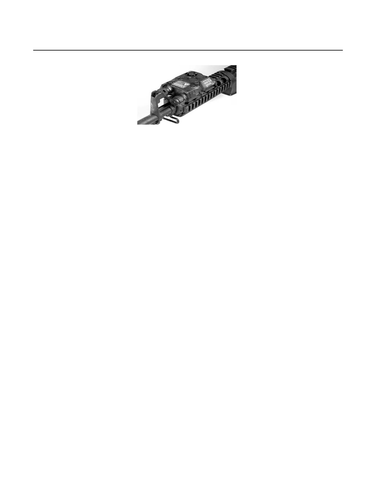
AN/PEQ-15 ADVANCED TARGET POINTER ILLUMINATOR AIMING LIGHT (ATPIAL)
TAMCN E17987G
NSN 5855-01-534-5931
ID 10470B
TM8K-076
DESCRIPTION AND FUNCTION
The ATPIAL provides a highly collimated beam of infrared energy for weapon aiming and an adjustable
focus infrared beam for target illumination. This Class 3b laser device also provides a highly collimated beam of
visible energy for weapon aiming. The ATPIAL has low profile aiming and illumination borelight adjusters. This
device is 50% smaller and lighter than the TPIAL. The system comes with a MIL-STD-1913 rail grabber interface
using the integral rail grabber bracket. The ATPIAL is the successor to the AN/PEQ-2A.
Intended Operators: One per individual and crew-served weapon in Ground Combat Element; one per
night vision goggles for Wing and MLG units.
Weapon Platforms: The ATPIAL has an integral rail grabber bracket that mounts to any weapon using the
standard MIL-STD-1913 rail, which includes the M4/M16 A4 rifles, M249, M240, M2, and MK 19. The ATPIAL can
also be used as a handheld illuminator/pointer.
TECHNICAL CHARACTERISTICS
Weight
7.5 oz (21.0 Kg)
Output Power
4.0 mW (±1.0 mW)
Battery Type
DL123A Lithium 3.0 V
Waterproof
To 19.68 ft (6 m)
(one needed)
Wavelength
605 to 665 Nm
Length
4.5 in. (11.43 cm)
Range
82 ft (25 m)
Width
2.8 in. (7.11 cm)
Divergence
0.5 mrad
Height
1.6 in. (4.06 cm)
MAJOR COMPONENTS
Qty
Item
Qty
Item
1
Case, Soft Carry
5
Generators, Pattern
1
Battery, DL123A (Lithium)
1
Strap, Retaining
1
Switch, Remote Cable
ASSOCIATED COMPONENTS
• Kit, Lens Cleaning
• Switch, Cable, 20-in.
• Switch, Cable, 25-in.
• Switch, Cable, 28-in.
• Borelight, Laser
REFERENCES
• TM 10470B-OI/1, Operator and Unit Maintenance Manual, Advanced Target Pointer Illuminator Aiming Light,
AN/PEQ-15.
• See SL-1-2 for a complete listing of applicable publications.
4-23
TM 8000-10/1D
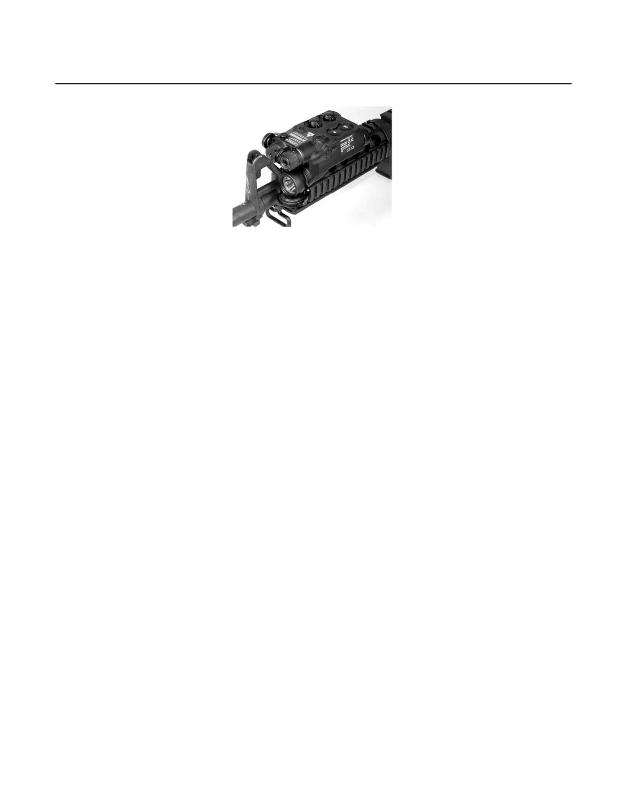
AN/PEQ-16 INTEGRATED POINTER/ILLUMINATOR MODULE (IPIM)
TAMCN E00587G
NSN 5855-01-538-5521
ID 104470A
TM8K-077
DESCRIPTION AND FUNCTION
This Class 3b laser device, the IPIM, provides a highly collimated beam of infrared energy for weapon aim-
ing and an adjustable focus infrared beam for target illumination. The IPIM is designed to withstand the shock of
heavy weapons. The White Light Illuminator provides target identification/illumination without night vision devices,
and is greater than 60 lumens in the high power mode. The IPIM has low profile aiming and illumination bore light
adjusters. This device can be used as a handheld illuminator/pointer or can be mounted to weapons with a MIL-
STD-1913 Rail. Will replace TPIAL along with ATPIAL and AN/PEQ-16A Mini-IPIM (MIPIM).
Intended Operators: One per Close Quarters Battle Weapon (CQBW) (kit).
Weapon Platforms: The IPIM has an Integral Rail Grabber Bracket that mounts to various weapons,
including M16A4, M4/M4A1, M240B, M249, and M240G. The IPIM has an M240/M249 Adapter Bracket.
TECHNICAL CHARACTERISTICS
Weight
11 oz (.31 kg)
Output Power
4.0 mW (±1.0 mW)
Battery Type
DL123A Lithium 3.0 V (two needed)
Waterproof
19.68 ft (6 m)
Length
5.5 in. (13.9 cm)
Wavelength
605 to 665 Nm
Width
2.9 in. (7.3 cm)
VIS Light
82 ft (25 m)
Height
2.3 in. (5.8 cm)
Divergence
0.5 mrad
Range
25 - 2,000 M
MAJOR COMPONENTS
Qty
Item
Qty
Item
1
Case, Soft Carry
1
Generators, Pattern (Set of Five)
1
Battery, DL123A Lithium 3.0 v
1
Strap, Retaining
1
Switch, Remote Cable
1
Bracket, Adapter (M240/M249)
1
Assembly, Bulb
ASSOCIATED COMPONENTS
• Kit, Lens Cleaning
• Grease, Silicone
• Switch, Cable, 20-in.
• Switch, Cable, 25-in.
• Switch, Cable, 28-in.
• Borelight, Laser
REFERENCES
• TM 10470B-OI/1, Operator and Unit Maintenance Manual, Advanced Target Pointer Illuminator Aiming Light,
AN/PEQ-15.
• See SL-1-2 for a complete listing of applicable publications.
4-24
TM 8000-10/1D
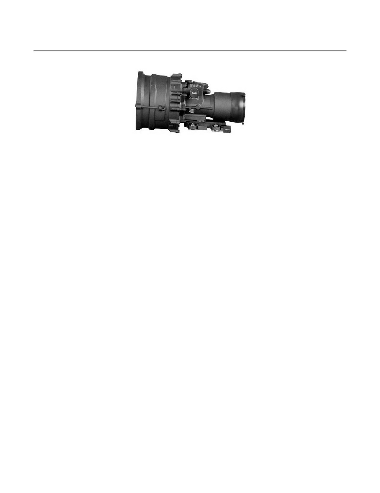
AN/PVS-27 SCOUT SNIPER MEDIUM RANGE NIGHT SIGHT (SSMRNS)
TAMCN E00207B
NSN 5855-01-547-9489
ID 8J671B
TM8K-078
DESCRIPTION AND FUNCTION
System Description: The SSMRNS will provide a new medium-range night sight capability that will inte-
grate with the M40A3, M82A3, and a semi-automatic sniper rifle. The SSMRNS is a lightweight, weapon
mounted, battery operated imaging device for engagement of targets at night and low light conditions. The
SSMRNS is an individual optic, capable of assisting scout sniper teams engaging targets during reduced light
and/or obscured targets with increased identification certainty from 400-800 yards. The SSMRNS shall be used in
conjunction with the Scout Sniper Day Scope (SSDS).
Intended Operators: Scout Sniper Teams and Designated Marksmen.
Weapon Platforms: The SSMRNS mounts to the M40A3 Sniper Rifle, MIL-STD-1913 Rail, and existing rail
systems on the M40A3, M82A3, and MK11 Mod1 Sniper Rifles.
TECHNICAL CHARACTERISTICS
Magnification
1X
Range:
Field of View
10 deg
Starlight
Weight
3.5 lb (w/o batteries)
Vehicle
3,444 yd (3,150 m)
3.7 lb (w/ batteries)
Man
1,476 yd (1,350 m)
Length
9 in. (22.8 cm)
1/4 Moon
Focus Range
15 m to infinity
Vehicle
4,450 yd (4,070 m)
Battery Type
AA 1.5 VDC (two needed)
Man
1,891 yd (1,730 m)
(Lithium or Alkaline)
Recognition Range
800-1,000 yd (731-914 m)
Battery Life
> 8 hours @ -25°F (-32°C)
> 18 hours @ ≥ 32°F (-36°C)
MAJOR COMPONENTS
Qty
Item
Qty
Item
1
Carrying/Storage Case
1
Wrench, Mount Adjustment
4
Battery, AA 1.5 VDC (2 Sets)
1
LENSPEN 1
1
2.0 x 40 Screwdriver
1
Card, Laminated, Light Shroud Instruction
1
Card, Laminated, Operation/Maintenance
1
Operator/Maintenance Manual
1
Lens Cover, Front
1
Anti-Reflection Device (ARD)
1
Lens Cover, Rear
1
Night Sight Assembly
(w/ lever actuated rail mount attached)
REFERENCES
• TM 11085B-OR/1, Operator Manual Sight, Night Vision Sniperscope AN/PVS-27.
• See SL-1-2 for a complete listing of applicable publications.
4-25

TM 8000-10/1D
ELECTRO-OPTICAL MAINTENANCE SHELTER COMPLEX (EOMSC)
TAMCN E00677B
NSN 5410-01-551-1127
ID 11424A
TM8K-101
TM8K-115
DESCRIPTION AND FUNCTION
System Description: The EOMSC Program is a maintenance program to replace all of the out-of-date
Electro-Optical Maintenance Shelter platforms in the Fleet Marine Force. The new Shelter Complex will provide a
larger working area while lessening the logistics embarkation footprint by half. It consists of three trailer-mounted
shelters with a flat rack to carry all ECUs, generators, ducting, power cables, and tenting.
Intended Operators: Electro-Optical Repairmen (MOS 2171).
TECHNICAL CHARACTERISTICS
Weight
135,980 lb (61,679 kg) (combined equipment)
Power Requirements
60 kw generator
4-26
TM 8000-10/1D
ELECTRO-OPTICAL MAINTENANCE SHELTER COMPLEX (EOMSC) - CONTINUED
MAJOR COMPONENTS
Qty
Item
TBD
TBD
ASSOCIATED COMPONENTS
• B1021
E0390
• E0070
E0430
• E0078
E0080
• B0030
E1260
• B0031
E0070
• E0079
A2546
• E1713
B0008
• E1022
E1948
• E3236
A7706
• E0360
REFERENCES
• Technical Manual in development.
• See SL-1-2 for a complete listing of applicable publications.
4-27

TM 8000-10/1D
MEDIUM RANGE THERMAL BI-OCULAR (MRTB)
TAMCN E00127G
NSN 5855-01-535-0971
ID 11237A
TM8K-121
DESCRIPTION AND FUNCTION
MRTB is a stand-alone, hand-held, battery-operated portable binocular used to observe/orient, detect, and
identify targets, conduct surveillance, and assist in engaging targets during all lighting conditions. It can be used
under conditions of limited visibility and battlefield obscurants such as smoke, fog, and sandstorms. This binocu-
lar will provide vision capabilities for tactical-range observation and machine gun fire direction and control. The
MRTB will have an integrated laser pointer with selectable Class 1 eye-safe mode and Class 3B combat mode to
designate targets, danger areas, and points of interest for Marines equipped with Image Intensifier devices such
as the AN/PVS-14 and AN/PVS-17 night vision systems.
TECHNICAL CHARACTERISTICS
Magnification
1.0X, 2.0X, 4.0X Digital
Zoom
Range
<550 m
Eye Pupil
TBD
Objective Lens
TBD
Length
TBD
Field of View
12 deg x 9 deg
Width
TBD
Reticle Adjustment
TBD
Weight
3.75 lb w/ batteries (1.70 kg)
Eye Relief
TBD
Battery Requirements
AA (four needed) (non-rechargeable)
MAJOR COMPONENTS
Qty
Item
TBD
TBD
ASSOCIATED COMPONENTS
• TBD
4-28

TM 8000-10/1D
INDIVIDUAL WEAPON NIGHT SIGHT-THERMAL (IWNS-T), AN/PAS-27
TAMCN E00627G
NSN 5855-01-559-7064
ID 11545A
TM8K-122
DESCRIPTION AND FUNCTION
IWNS-T is a clip-on thermal sight that will be used in conjunction with the RCO in the M16A4 service rifle
and M4 carbine. The IWNS-T will attach in front of the RCO to the MIL-STD-1913 rail system, while maintaining
zero. This thermal device is a portable, battery operated, electro-optical sight used to locate and engage targets
during day, night, and other adverse conditions such as light rain, light snow, and dry smoke.
TECHNICAL CHARACTERISTICS
Magnification
1.0X (with RCO) and 2.0X Digital
Zoom
Range
546 yd (500 m)
Height
3.8 in. (96.5 mm)
Field of View
12 deg
Weight
<2 lb (.74 kg) w/ batteries
Length
7.3 in. (185.4 mm)
Battery
4 DL123A Lithium
Width
2.9 in. (73.66 mm)
(four needed)
MAJOR COMPONENTS
Qty
Item
Qty
Item
1
Soft case
8
Batteries
1
Operator’s Manual
1
Video Cable
1
Lens Kit
1
Interface Hood
1
Quick Reference Guide (QRG)
ASSOCIATED COMPONENTS
• TBD
REFERENCES
• TM 11545A-OR
4-29

TM 8000-10/1D
AN/PVS-21 LOW PROFILE NIGHT VISION GOGGLES (LP-NVG)
TAMCN E00617B
NSN 5855-01-511-0994
ID 11487A
TM8K-081
DESCRIPTION AND FUNCTION
The AN/PVS-21 Low Profile Night Vision Goggle (LP-NVG) design enables aggressive night mobility. The
low-profile design with a total depth of just over 3 inches is unequaled for aggressive night operations such as
rapid terrain traversal, weapons employment, parachuting, close-quarter battle, and vehicle operations. The see-
through optics design eliminates tunnel vision and enables smooth, natural transition from dark to light, defeats
blinding glare, and improves operations during ambient light surges. The AN/PVS-21 has the Enhanced Heads
Up Display (EHUD) that allows integration of additional sensors/systems into a single image.
TECHNICAL CHARACTERISTICS
Range
13 in. (33 cm) to infinity
Length
TBD
Field of View
40 deg
Weight
1.68 lb (1.72 kg)
w/ battery
Magnification
1.0X
Battery Type
Lithium or 3.6 VDC Lithium
(one needed)
MAJOR COMPONENTS
Qty
Item
TBD
TBD
ASSOCIATED COMPONENTS
• TBD
REFERENCES
• STS Inc., Beavercreek, OH
4-30

TM 8000-10/1D
AN/PVS-24A INDIVIDUAL WEAPON NIGHT SIGHT I2 (IWNS-I2)
TAMCN E00087G
NSN 5855-01-558-3616
ID 11499A
TM8K-082
DESCRIPTION AND FUNCTION
IWNS-I2 is an individual imaging device capable of acquiring targets at night with increased recognition cer-
tainty when used in conjunction with the RCO variants.
TECHNICAL CHARACTERISTICS
Range
153 yd (140 m)
Length
5.8 in. (147.3 mm)
Magnification
1.0X
Width
3.7 in. (93.98 mm)
Battery Type
CR123A Lithium battery
Height
3.3 in. (83.8 mm)
(one needed) or AA Alkaline
battery (one needed)
Weight
1.70 lb (.71 kg) w/ batteries
MAJOR COMPONENTS
Qty
Item
Qty
Item
1
Soft Case
3
Batteries
1
Operator Manual
1
Battery Adapter
1
Quick Reference Guide (QRG)
1
Objective Hood
1
Lens Kit
1
Interface Hood
1
Wrench - 3/8 in.
ASSOCIATED COMPONENTS
• TBD
REFERENCES
• Insight Technology Inc., Londonderry, NH
• TM 11499A-OR
4-31

TM 8000-10/1D
AN/PEQ-16A MINI-INTEGRATED POINTER/ILLUMINATOR MODULE (MIPIM)
TAMCN E00587G
NSN 5855-01-550-2780
ID 11407C
TM8K-127
DESCRIPTION AND FUNCTION
This is a Class 3b laser device that provides a highly collimated beam of infrared energy for weapon aiming
and an adjustable focus infrared beam for target illumination. The MIPIM is designed to withstand the shock of
heavy weapons. The White Light Illuminator provides target identification/illumination without night vision devices,
and is greater than 60 lumens in the high power mode. The MIPIM has low profile aiming and illumination bore
sight adjusters. This device can be used as a MIL-STD-1913 Rail. This item is planned to replace the TPIAL along
with the ATPIAL and IPIM.
TECHNICAL CHARACTERISTICS
Range:
Wavelength
605-665 nm visible
Laser
25-2,000 m
820-860 nm infrared aiming
Visible Light
50 m
820-860 nm infrared illumination
Battery Type
DL123A Lithium or equivalent
Range
25 m visible
(two needed)
600 m infrared aiming (LOW)
Weight
9.9 oz (.28 kg) w/ batteries
2,000 m infrared aiming (HIGH)
Height
2.3 in. (58.42 mm)
600 m infrared illumination (LOW)
Width
2.9 in. (73.66 mm)
2,000 m infrared illumination (HIGH)
Length
5.5 in. (139.7 mm)
Output Power
4.0 mW (± 1.0 nW)
MAJOR COMPONENTS
Qty
Item
TBD
TBD
ASSOCIATED COMPONENTS
• TBD
REFERENCES
• Insight Technology Inc., Londonderry, NH
4-32

TM 8000-10/1D
AN/PEQ-14 INTEGRATED LASER WHITE LIGHT POINTER (ILWLP)
TAMCN E09577B
NSN 5855-01-538-0191
ID 10820C
TM8K-084
DESCRIPTION AND FUNCTION
The AN/PEQ-14 ILWLP is a Class 3b laser device that provides the user with either visible or infrared illumi-
nation of the target for target acquisition, and either visible or infrared target aiming point for fire control. Both
laser beams can be zeroed to the weapon and each other. The laser beams can also be operated in combination
with the visible and IR illumination beams.
TECHNICAL CHARACTERISTICS
Range:
Laser
328 ft (100 m) minimum; visible
Light
82 ft (25 m)
Battery Type
DL123A Lithium or equivalent (two needed)
Weight
6 oz (.18 kg) with batteries
MAJOR COMPONENTS
Qty
Item
TBD
TBD
ASSOCIATED COMPONENTS
• TBD
REFERENCES
• Insight Technology Inc., Londonderry, NH
4-33
TM 8000-10/1D
SCOUT SNIPER OBSERVATION TELESCOPE (SSOT)
TAMCN E00167B
NSN TBD
ID TBD
TBD
DESCRIPTION AND FUNCTION
The SSOT is a lightweight, variable power, tripod mounted telescope that will replace the out-dated M49
Sniper 20X power fixed telescope throughout the United States Marine Corps. The SSOT is used for detecting,
recognizing, observing, identifying, and ranging targets during daylight with increased identification certainty. The
Sniper Observer Night Observation Device. The intent of the SSOT is to provide the Marine Scout Sniper Team
with enhanced ability to clearly, easily, and quickly engage targets out to the maximum effective range of the indi-
vidual weapons during the day and when used in conjunction with the SSMRNS in night and low light conditions.
TECHNICAL CHARACTERISTICS
Range
TBD
Width
TBD
Magnification
TBD
Weight
TBD
Battery Type
N/A
Range
TBD
MAJOR COMPONENTS
Qty
Item
TBD
TBD
ASSOCIATED COMPONENTS
• TBD
REFERENCES
• TBD
4-34

TM 8000-10/1D
SOUND COMMANDER 3600 (SC3600)
TAMCN A02507G
NSN TBD
ID TBD
TM8K-129
DESCRIPTION AND FUNCTION
The SC3600 tactical sound system generates clear, articulate audio at a continuous volume level of 134dB
(RMS). The SC3600 can reach out to ranges beyond 2,000 meters. The system, with exception of the adjustable
equipment stand, is contained within two rugged Roto-Mold hard cases. The first case contains a high-quality,
multiple input audio controller/preamplifier; power amplifier; internal three-speaker reentrant horn array; and
hands-free headset microphone, three-tone siren, and internal 12 VDC rechargeable battery pack. The second
Roto-Mold hard case contains an additional three loudspeaker, horizontal array (also removable for remote oper-
ation), and an additional soft accessory storage case in the lid. Hardware is included for stacking and locking one
case on top of the other, thus forming a single stacked array of six loudspeakers, offering maximum power projec-
tion in one direction.
TECHNICAL CHARACTERISTICS
Power Rqmts
12 VDC
Range
328 to 2,187 yd (300 to 2,000 m)
Weight:
Operational
76 lb (34.5 kg)
Stowage
92 lb (42 kg)
MAJOR COMPONENTS
Qty
Item
2
Molded Hard Cases
2
3-Speaker Arrays
1
Stacking/Locking Hardware
1
Audio Controller/Preamplifier
1
Power Amplifier
1
Hands-Free Headset/Microphone
1
Three-Tone Siren
1
12 VDC Rechargeable Battery Pack
2
Soft Accessory Storage Case
1
Adjustable Equipment Stand w/ Case
1
AC/DC Power Supply/Charger
ASSOCIATED COMPONENTS
• TBD
REFERENCES
• TBD
4-35
TM 8000-10/1D
NON-LETHAL/TUBE LAUNCHED MUNITION SYSTEM (NL/TLMS)
TAMCN C00247B
NSN 1055-01-563-6749
ID 11586A
TM8K-123
DESCRIPTION AND FUNCTION
The NL/TLMS is a 40 mm, multi-shot, electrically-actuated, non-lethal munitions grenade launcher mounted
to the High Mobility Multi-purpose Wheeled Vehicle (HMMWV) turret blast shield. The NL/TLMS system consists
of three banks of 10 launch tubes, each at fixed angles of 10, 20, and 30 from the horizontal, achieving 360-
degree coverage by traversing the HMMWV turret. The Non-Lethal/Tube Launched Munitions System fires a
multi-flash-bang grenade out to ranges beyond 100 m. The system is comprised of three subsystems: launcher,
firing circuit, and ammunition. NL/TLMS will provide Marine Forces the ability to deliver a high volume of non-
lethal fire at range, both day and night, enhancing convoy security operations. NL/TLMS will enable Marines to
deter and dissuade errant vehicle operators from encroaching into security zones by helping to determine intent
and increasing standoff distance and reaction time in responding to threats.
TECHNICAL CHARACTERISTICS
Power Rqmts
12 VDC
Battery
AA, Alkaline (six needed)
Range
120 m (± 10 m)
Field of Fire
10 deg, 20 deg, and 30 deg
Magazine
30 rounds
banks
Coverage
360 deg
Weight
34 lb without ammunition
Munitions
Flash-bang
65 lb with ammunition
MAJOR COMPONENTS
Qty
Item
TBD
TBD
ASSOCIATED COMPONENTS
• TBD
REFERENCES
• Combined Tactical Systems, Jamestown, PA
4-36

TM 8000-10/1D
MISSION PAYLOAD MODULE - NON-LETHAL WEAPONS SYSTEMS
TAMCN E00327M
NSN TBD
ID TBD
TM8K-124
DESCRIPTION AND FUNCTION
The Mission Payload Module (MPM) - Non-Lethal Weapons System is being developed to engage group
targets and deter personnel from conducting potentially hostile acts while minimizing the possibility of permanent
injury or death. When fielding, the MPM will provide greater range and standoff distances than existing non-lethal
munitions and will address current shortcomings and operational deficiencies in volume of (non-lethal) fire against
area targets. The availability of the longer-range non-lethal capability mounted on a variety of platforms will allow
U.S. commanders to engage threatening personnel in a graduated, non-lethal manner, short of employing lethal
force. The U.S. Marine Corps is currently in Technology Development and will proceed into System Development
and Demonstration in FY09.
TECHNICAL CHARACTERISTICS
Power Rqmts
TBD
Range
492 ft (150 m)
Duration
TBD
Accuracy
TBD
MAJOR COMPONENTS
Qty
Item
TBD
TBD
ASSOCIATED COMPONENTS
• TBD
REFERENCES
• TBD
4-37

TM 8000-10/1D
NITROGEN GENERATOR
TAMCN E00807B
NSN 3655-01-556-1083
ID 11483A
TM8K-086
DESCRIPTION AND FUNCTION
The N2-GEN™ provides an economical, precise means of generating high-purity nitrogen. The system con-
sists of an internal nitrogen generator and air compressor and extracts nitrogen from air. The nitrogen is gener-
ated by means of the air compressor pushing air into the simple membrane element, which in turn mechanically
separates nitrogen molecules from other molecules found within air.
TECHNICAL CHARACTERISTICS
Power Rqmts
110 VAC; 20-amp breaker
Range
N/A
Weight
75 lb (34 kg)
MAJOR COMPONENTS
Qty
Item
TBD
TBD
ASSOCIATED COMPONENTS
• TBD
REFERENCES
• South-Tek, Raleigh, NC
4-38

TM 8000-10/1D
SHOP EQUIPMENT CONTACT MAINTENANCE VEHICLE (SECMV)
TAM C70077B
NSN 4940-01-552-1599
ID 11446A
TM8K-102
DESCRIPTION AND FUNCTION
The SECMV will provide a contact maintenance capability that will allow Marines to travel forward of the bat-
tle area and perform limited preventive and corrective maintenance on all types of Marine Corps weapons sys-
tems. The SECMV shall be a M1152 HMMWV with an S-788/G Short Shelter designed to provide “As Far
Forward As Possible”, Operator/Crew and Field Level maintenance capability for the maintenance/repair of com-
bat equipment and weapon systems throughout the Marine Corps.
TECHNICAL CHARACTERISTICS
Power Rqmts
AC Shore Power Capable/DC Power
generated by HMMWV via on-board
5000W DC/AC inverter
Range
N/A
Weight:
M1152 Straight Leg
9,595 lb (4,352 kg)
M1152A
10,295 lb (4,670 kg)
M1152 Up Armored
11,955 lb (5,423 kg)
MAJOR COMPONENTS
Qty
Item
TBD
TBD
ASSOCIATED COMPONENTS
TAM #
ID #
Nomenclature
Type/Model
B00074BA
11453A
Air Conditioner, 0.75 Ton, 9,000 BTU/hr,
9KECU
60 Hz
(NSN 4120-01-552-5225)
D00227KA
11285A
Truck, Utility
M1152
(NSN 2320-01-518-7332
A0126
11255A
Radio Set, Multi-band High-Frequency
AN/VRC-103
Vehicle-Mounted
(NSN 5820-01-537-7562)
A25467GA
10838F
Laptop, Ruggedized
Tough Book Laptop
(NSN 7010-09-000-4287)
E00807B
11483B
Nitrogen, Generator
(NSN 3655-01-556-1083)
REFERENCES
• Systems integrator is Marine Corps Logistics Base, Barstow, CA.
4-39

TM 8000-10/1D
TOOL KIT, ELECTRO-OPTICAL (EOTK)
TAMCN E22082B
NSN 5180-01-382-1335
ID 09863A
TM8K-090
DESCRIPTION AND FUNCTION
The EOTK is intended to be issued as an individual tool kit for the Electro-Optical Ordnance Repairer (MOS
2171) who inspects, tests, and repairs Marine Corps electrical optics. The Electro-Optical Tool Kit will support all
the Electro-Optical equipment in the Marine Corps. The optics serviced by this kit include, but are not limited to,
are the E0139 M3 Bore Scope, E0180 M292 Aiming Circle, E0205 M1A2 Collimator, E0325 AN/UAS12 Night
Vision Equipment, E1045 AN/PAQ3 Laser Equipment, E1152 AN/PVS-7 Night Vision Goggles, E1154 AN/PVS-
14 Night Vision Goggles, E1159 AN/PVS-5 Night Vision Sight, and E1900 M49 Telescope.
TECHNICAL CHARACTERISTICS
Power Rqmts
Not Applicable
Range
N/A
Weight
70 lb
MAJOR COMPONENTS
Qty
Item
TBD
TBD
ASSOCIATED COMPONENTS
TAM #
Nomenclature
E10227B
Night Sight Shelter
E17137B
Optics Shelter
E32367B
TOW Shelter
E70077B
SECM Vehicle
REFERENCES
• TBD
4-40

TM 8000-10/1D
INFANTRY BINOCULARS - TACTICAL COTS
TAMCN E00847B
NSN 6650-01-559-3648
ID 11539A
TM8K-091
DESCRIPTION AND FUNCTION
The Tactical Infantry Binocular is a hand-held binocular. This system will aid the individual Marine in target
detection, recognition, and identification of threats. The ability of Marines to identify IEDs from greater distances
and locate snipers shall be enhanced, thereby increasing the combat effectiveness and lethality of the Marine.
TECHNICAL CHARACTERISTICS
Power Rqmts
N/A
Intended Effects
TBD
Duration
N/A
Weight
22.9 oz (.64 kg)
Accuracy
N/A
MAJOR COMPONENTS
Qty
Item
TBD
TBD
ASSOCIATED COMPONENTS
• TBD
REFERENCES
• Leupold & Stevens, Inc. Beaverton, OR.
4-41

TM 8000-10/1D
SU-260P MACHINE GUN DAY OPTIC (MDO)
TAMCN E00887B
NSN 1240-01-578-0211
ID 11792A
TM8K-125
DESCRIPTION AND FUNCTION
Medium Machine Gun Day Optic (MDO) will be a magnified day optic that mounts on the M240B Medium
Machine Gun. This system will aid the machine gunner in target detection, recognition, and identification, thereby
increasing the combat effectiveness and lethality of the machine gun team.
TECHNICAL CHARACTERISTICS
Magnification
6.0X
Power Source
Fiber Optic/Tritium
Intended Effects
TBD
Battery Life
Not Applicable
Recognition Range
1,312 yds (1,200 m)
Field of View
3.2 deg
Weight
2.7 lb (1.2 kg)
MAJOR COMPONENTS
Qty
Item
TBD
TBD
ASSOCIATED COMPONENTS
• TBD
REFERENCES
• TBD
4-42

TM 8000-10/1D
SU-258/PVQ SQUAD DAY OPTIC (SDO)
TAMCN E00827B
NSN 1240-01-575-1724
ID TBD
TM8K-126
DESCRIPTION AND FUNCTION
M249 Squad Automatic Weapon Day Optic (SDO) will be a magnified day optic that mounts on the M249
Squad Automatic Weapon and Infantry Automatic Rifle (IAR). This system will aid the automatic rifleman in target
detection, recognition, and identification, thereby increasing the combat effectiveness and lethality of the Marine
Corps fire team.
TECHNICAL CHARACTERISTICS
Magnification
3.5X
Power Source
Fiber Optic/Tritium
Intended Effects
TBD
Battery Life
Not Applicable
Recognition Range
1,094 yds (1,000 m)
Field of View
5.5 deg
Weight
1.3 lb (.59 kg)
MAJOR COMPONENTS
Qty
Item
TBD
TBD
ASSOCIATED COMPONENTS
• TBD
REFERENCES
• TBD
4-43/(44 Blank)
TM 8000-10/1D
CHAPTER 5
ANCILLARY EQUIPMENT
TM 8000-10/1D
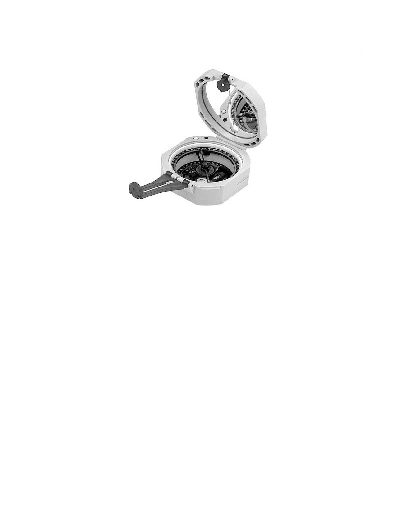
COMPASS, MAGNETIC, M2
TAMCN E02102E
NSN 1290-00-930-4260
ID 00477A
TM8K-103
DESCRIPTION AND FUNCTION
Compass, Magnetic, M2 is a multiple purpose instrument used for obtaining clinometer, angle of sight, and
azimuth readings. The body of the compass is dust proof and moisture proof and is made of nonmagnetic mate-
rial, except for the magnetic needle and its pivot. When the cover is closed, the magnetic needle is automatically
lifted from its pivot to protect the pivot point and jewel bearing, which is agate. The compass is provided with an
angle of sight scale and azimuth scale. The azimuth scale may be rotated approximately 1,800 roils. The com-
pass is equipped with circular and tubular levels, and it employs front and rear leaf sights in conjunction with a
mirror in the cover for sighting and reading the angles. The instrument has an azimuth scale adjuster for orienting
the azimuth scale to the local magnetic declination so that the grid of Y-azimuths may be read directly.
TECHNICAL CHARACTERISTICS
Weight
8 oz (226.8 g)
Azimuth Scale
0 to 6,400 roils
Dimensions (Closed)
2-3/34 x 1-1/8 in.
Angle of Site Scale
1,200 - 0 - 1,200 roils
(6.99 x 2.86 cm)
MAJOR COMPONENTS
Qty
Item
Item Qty
1
Compass Body
1
Azimuth Scale
1
Cover
1
Front and Rear Leaf Sights
ASSOCIATED COMPONENTS
• None
REFERENCES
• SL-3-00477A; Components List, Compass, Magnetic Unmounted, M2, W/E.
• TM 9-1290-333-15; Operator and Maintenance Manual, Compass, Magnetic, Unmounted, M2.
• See SL-1-2 for a complete listing of applicable publications.
5-1

TM 8000-10/1D
QUADRANT, FIRE CONTROL, GUNNER’S, M1A2
TAMCN E12607B
NSN 1290-00-169-1937
ID 02193C
TM8K-093
DESCRIPTION AND FUNCTION
Quadrant, Fire Control, Gunner’s, M1A2 is a portable, precision-leveling instrument used for laying artillery
weapons in elevation, measuring their angles of elevation, and checking the adjustments of elevating mecha-
nisms on sighting and fire control equipment. It consists of a sector-shaped frame to which is pivoted a leveling
radial arm carrying a level vial tube assembly. Four frame shoes, arranged in pairs, provide two reference sur-
faces at right angles to each other for seating the instrument when taking readings. Machined teeth on the inside
arc of the frame engage with a spring-loaded plunger in the radial arm to permit rapid setting of the arm in coarse
10-mil steps, as read on elevation scales provided on each side of the frame. The left scale is used for elevations
from 0 to 800 mil and the right scale is used for elevations from 800 to 1,600 mil. The leveling radial arm has a
micrometer graduated in 0.2-mil steps for fine adjustment. When the level bubble is centered, elevation is read as
the sum of the coarse and fine scale readings.
TECHNICAL CHARACTERISTICS
Course Elevation Scales:
Width
1-1/16 in. (2.7 cm)
Lower
0 to 800 mil
Height
6 in. (15.24 cm)
Upper
800 to 1,600 mil
Weight
1.8 lb (0.82 kg)
Length
6-7/8 in. (17.46 cm)
MAJOR COMPONENTS
Qty
Item
Qty
Item
1
Holder
1
Radial Arm Plunger
1
Level Vial
1
Data Plate
1
Frame Assembly
4
Frame Shoes
1
Left Elevation Scale
1
Right Elevation Scale
1
Micrometer
ASSOCIATED COMPONENTS
• Case, Carrying, M82
REFERENCES
• TM 02193C-14&P; Operator’s and Maintenance Manual, Quadrant, Fire Control Gunner’s, M1A2.
• See SL-1-2 for a complete listing of applicable publications.
5-2

TM 8000-10/1D
SIGHT, BORE, OPTICAL, M45/M45A1
TAMCN E17802E
NSN 1240-00-152-3512
ID 02368B
TM8K-094
DESCRIPTION AND FUNCTION
Sight, Bore, Optical, M45/M45A1 is a fixed-focus telescope adapted for use to align the bore axis of the
mortar M224/M252 with a distant aiming point. The boresight is constructed so that the telescope line of sight lies
in the plane established by the center lines of the V-slides. When the boresight is properly secured to the mortar
tube, the center line of the contracting V-slide is parallel to the center line and the mortar tube ties in the same
vertical plane.
TECHNICAL CHARACTERISTICS
Weight
2.5 lb (1.13 kg)
Field of View
12 deg (12 min)
Length
4.5 in. (11.43 cm)
Diameter of Exit Pupil
0.15 in. (0.38 cm)
Width
4 in. (10.16 cm)
Equivalent Focal Length
2.362 in. (5.99 cm)
Height
4.75 in. (12.07 cm)
of Objective
Magnification
3X
Clear Eye Distance
0.604 in. (1.53 cm)
MAJOR COMPONENTS
Qty
Item
Qty
Item
1
Clamp, Assembly
1
Telescope, Elbow, M62A1C
2
Strap, Assembly
ASSOCIATED COMPONENTS
• Case, Carrying, M45
REFERENCES
• TM 02368B-24&P; Maintenance Manual, Optical Boresight, M45 / M45A1.
• See SL-1-2 for a complete listing of applicable publications.
5-3

TM 8000-10/1D
SIGHT UNIT, M64A1
TAMCN N/A
NSN 1240-01-201-8299
ID 88129C
TAMCN
NSN 1240-01-211-3608
TM8K-095
DESCRIPTION AND FUNCTION
Sight Unit, M64A1 consists of the telescope elbow and telescope mount. It is used to lay the mortar M224/
M252 in deflection and elevation. The elbow is 1.5 power, hermetically sealed with a tritium illuminated cross hair
reticle. The mount is provided with tritium backlighted level vials, indices, and translucent plastic scales for use in
orientating the telescope elbow in azimuth and elevation.
TECHNICAL CHARACTERISTICS
Weight
2.5 lb (1.1 kg)
Elevation
0 to 6,400 mils
Field of View
302 mil (17 deg)
Azimuth
0 to 6,400 mils
Magnification
1.5X nominal
MAJOR COMPONENTS
Qty
Item
Qty
Item
1
Telescope, Elbow
1
Elevation Knob/Scale
1
Mount, Telescope
1
Azimuth Knob/Scale
ASSOCIATED COMPONENTS
• Case, Carrying
REFERENCES
• TM 9-1010-223-10; Operator’s Manual for Lightweight Company Mortar 60 mm M224.
• TM 88129C-24&P; Maintenance Manual, M64A1 Sight Unit.
• See SL-1-2 for a complete listing of applicable publications.
5-4
TM 8000-10/1D
CHAPTER 6
EQUIPMENT LISTING BY TAM-NUMBER SEQUENCE
TM 8000-10/1D
EQUIPMENT LISTING BY TAM-NUMBER SEQUENCE
TAMCN
ID
NSN
ITEM DESCRIPTION
MODEL
PAGE
INFANTRY WEAPONS
E0055
TBD
TBD
Launcher System, Saber, M41 (ITAS)
M41
1-7
E00252M
11235A
1010-01-535-0989
Launcher, Grenade, Multi-Shot, 40 mm
M32
1-14
E00817
TBD
1005-01-557-2693
Mount, Vehicle, Medium Machine Gun,
M35
1-25
M35 (MMGVM)
E01907M
10012B
1005-01-382-0953
Carbine, 5.56 mm, M4A1 Close
M4A1 CQBW
1-3
Quarters Battle Weapon (CQBW)
E01957M
10012A
1005-01-231-0973
Carbine, 5.56 mm, M4
M4
1-1
E02077B
09397B
1430-01-478-5345
Javelin Weapons System, Command
M98A1
1-9
Launch Unit (CLU)
E03117M
11473A
1005-01-553-5196
Rifle, 7.62 mm, M14, Enhanced
EMR
1-32
Marksman Rifle (EMR)
E08927M
07700B
1010-01-434-9028
Launcher, Grenade, 40 mm
M203A1
1-13
E08927M
07700A
1010-00-179-6447
Launcher, Grenade, 40 mm
M203
1-12
E09157M
08673A
1055-01-164-4608
Launcher, Assault, Rocket, 83 mm
MK 153
1-10
(SMAW)
E09357B
07722B
1440-01-104-9834
Guided Missile System, TOW 2
M220E4
1-5
Weapon System
E09607M
08671A
1005-01-127-7510
Machine Gun, Light, Squad, 5.56 mm
M249
1-21
E0961
09111A
1005-01-252-4288
Machine Gun, 7.62 mm
M240E1
1-16
E09807M
02498B
1005-00-726-5636
Machine Gun, Caliber .50, M2, Heavy
M2
1-19
Barrel, Flexible
E0984
02498C
1005-00-957-3893
Machine Gun, Caliber .50, Browning,
M2 - M48
1-20
M2, Heavy Barrel, Flexible, M48 Turret
Type
Type
E09897M
09712B
1005-01-412-3129
Machine Gun, 7.62 mm
M240B
1-17
E09947M
08521B
1010-01-430-9697
Machine Gun, 40 mm, MK 19 w/BKT
1-18
E09987M
08670A
1005-01-025-8095
Machine Gun, 7.62 mm
M240
1-15
E10657M
08206A
1010-01-020-5626
Mortar, 60 mm, Lightweight, Company
M224
1-22
E10957M
09922A
1015-01-164-6651
Mortar, Medium, Extended Range,
M252
1-23
81 mm
E11202M
06510A
1005-00-710-5599
Mount, Tripod, Machine Gun, 7.62 mm
M122
1-28
E11232B
09017A
1010-01-180-9319
Mount, Machine Gun, MK64
MOD 5
1-24
E11232B
08017B
1010-01-502-7547
Mount, Machine Gun, MK93
MK93
1-27
E11262B
07937A
1005-00-322-9716
Mount, Tripod, Machine Gun, Caliber
M3
1-29
.50
6-1

TM 8000-10/1D
EQUIPMENT LISTING BY TAM-NUMBER SEQUENCE - CONTINUED
TAMCN
ID
NSN
ITEM DESCRIPTION
MODEL
PAGE
E12452M
08993B
1005-01-525-7966
Pistol, Semi-Automatic, 9 mm
M9A1
1-31
E12502M
08993A
1005-01-118-2640
Pistol, Semi-Automatic, 9 mm
M9
1-31
E12512M
09795B
1005-01-521-4072
Pistol, M45 Close Quarters Battle
M45 CQBP
1-30
Pistol (CQBP) .45 Caliber
E14412M
05538C
1005-01-128-9936
Rifle, 5.56 mm, M16A2
M16A2
1-33
E14412M
05538C
1005-01-383-2872
Rifle, 5.56 mm, M16A4
M16A4
1-34
E14602M
05539D
1005-01-495-0843
Rifle, Sniper, 7.62 mm
M40A3/A5
1-36
E14752M
11110A
1005-01-469-2133
Rifle, Scoped, Long Range, Caliber .50
M107
1-35
E17612M
10698A
1005-01-472-3147
Shotgun, 12 Gage, M1014, Joint
M1014
1-37
Service Combat Shotgun (JSCS)
E17622M
09081A
1005-01-371-5639
Shotgun, 12 Gage, Mossberg
500A2
1-38
TOWED ARTILLERY WEAPONS
E06657M
08198A
1025-01-026-6648
Howitzer, Medium, Towed, 155 mm
M198
2-1
E06717M
10407A
1025-99-463-7551
Howitzer, M777A2
M777A2
2-3
TRACKED AND WHEELED COMBAT VEHICLES
E01507B
08940A
5420-00-889-2020
Bridge, Armored Vehicle Launched
3-13
E07967K
07268B
2350-01-458-7318
Assault Amphibian Vehicle, Command
AAVC7A1
3-5
E08467K
09674A
2350-01-458-7410
Assault Amphibian Vehicle, Personnel
AAVP7A1
3-1
Carrier
E08567K
07267B
2350-01-458-7550
Assault Amphibian Vehicle, Recovery
AAVR7A1
3-8
E09427M
08652A
2320-01-123-1609
Light Armored Vehicle (LAV) - Anti-
LAV-AT
3-17
Tank
E09467B
08650A
2320-01-123-1606
Light Armored Vehicle (LAV) -
LAV-C²A1
3-18
Command and Control
E0947
08672A
1005-01-086-1400
Gun, Automatic, 25 mm
M242
3-14
E09477M
08594A
2320-01-123-1602
Light Armored Vehicle (LAV) - Light
LAV-25A1
3-19
Assault
E09487B
08654A
2320-01-123-1612
Light Armored Vehicle (LAV) -
LAV-L
3-20
Logistics
E09497M
08655A
2320-01-123-1607
Light Armored Vehicle (LAV) - Mortar
LAV-M
3-22
E09507B
08651A
2320-01-123-1608
Light Armored Vehicle (LAV) -
LAV-RA1
3-21
Maintenance/Recovery
E09967M
09147A
2590-01-230-8862
Blade, Mine Clearing
M1A1
3-12
E13787K
07769B
2350-01-390-4683
Recovery Vehicle, Heavy, Full-Tracked
M88A2
3-23
6-2
TM 8000-10/1D
EQUIPMENT LISTING BY TAM-NUMBER SEQUENCE - CONTINUED
TAMCN
ID
NSN
ITEM DESCRIPTION
MODEL
PAGE
E1500
10937A
1055-01-473-4350
High Mobility Artillery Rocket System
M142
3-15
(HIMARS)
E18887M
08953A
2350-01-087-1095
Tank, Combat, Full-Tracked, 120 mm
M1A1
3-25
Gun
E3201
10004A
1010-01-233-9493
Assault Amphibian Vehicle, Personnel
AAVP7A1
3-3
Carrier, Model 7A1, Upgunned
Weapons Station (UGWS)
OPTICAL AND MISCELLANEOUS EQUIPMENT
A02507G
TBD
TBD
Sound Commander 3600
SC3600
4-35
C70077B
11446A
4940-01-552-1599
Shop Equipment Contact Maintenance
4-39
Vehicle (SECMV)
E00067B
11173A
5855-01-502-6414
Infrared Zoom Laser Illuminator
1000P-A1
4-21
Designator (IZLID)
E00087G
11499A
5855-01-558-3616
Individual Weapon Night Sight I²
AN/PVS-24A
4-31
(IWNS-I²)
E00167B
TBD
TBD
Scout Sniper Observation Telescope
4-34
(SSOT)
E17107G
11064A
1240-01-525-1648
Rifle, Combat Optics (RCO)
AN-PVQ-31A
4-18
(A4)
(A4)
E00177M
11064B
1240-01-534-1114
Rifle Combat Optics (RCO) AN/PVQ-
AV/PVQ-31B
4-18
(M4)
(M4)
31B (M4)
(M4)
E00207B
8J671B
5855-01-547-9489
Scout Sniper Medium Range Night
AN/PVS-27
4-25
Sight (SSMRNS)
E00387B
11452A
5855-01-552-3289
Visible Light Illuminator Replacement
AN/PVS-29
4-20
(VLIR)
E00537B
11352A
5860-01-544-7175
Non-Lethal Visual Hailing Device
GBD-IIIC,
4-22
LA-9/P
E00587G
104470A
5855-01-538-5521
Integrated Pointer/Illuminator Module
AN/PEQ-16
4-24
(IPIM)
E00587G
11407C
5855-01-550-2780
Mini-Integrated Pointer/Illuminator
AN/PEQ-16A
4-32
Module (MIPIM)
E00617B
11487A
5855-01-511-0994
Low Profile Night Vision Goggles
AN/PVS-21
4-30
(LP-NVG)
E00627G
11545A
5855-01-559-7064
Individual Weapon Night Sight-
AN/PAS-27
4-29
Thermal (IWNS-T)
E00637G
11532A
5855-01-554-4673
Mini Thermal Imager (MTI)
4-1
E00677B
11424A
5410-01-551-1127
Electro-Optical Maintenance Shelter
4-26
Complex (EOMSC)
E00807B
11483A
3655-01-556-1083
Nitrogen Generator
N2-GEN™
4-38
6-3
TM 8000-10/1D
EQUIPMENT LISTING BY TAM-NUMBER SEQUENCE - CONTINUED
TAMCN
ID
NSN
ITEM DESCRIPTION
MODEL
PAGE
E00847B
11539A
6650-01-559-3648
Infantry Binoculars - Tactical COTS
4-41
E00957B
11700A
1240-01-571-5004
Scout Sniper Periscope (SSP)
SSVZ-S
4-15
E09567A
10471A
5860-01-466-2087
Laser Boresight System (LBS)
AN/PEM-1
4-14
E09567B
10471B
5860-01-471-2091
Laser Boresight System (LBS),
AN/PEM-1
4-4
AN/PEM-1
E09577B
10820A
5860-01-491-9639
Light Module, Integrated Laser (ILLM)
AN/PEQ-6A
4-7
E09577B
10820C
5855-01-538-0191
Integrated Laser White Light Pointer
AN/PEQ-14
4-33
(ILWLP)
E11522B
09500A
5855-01-228-0937
Night Vision Goggles, Individual
AN/PVS-7B
4-9
10497A
(7B)
and -7D
E11522BA
5855-01-422-5413
(7D)
E11542B
10271A
5855-01-432-0524
Monocular Night Vision Device,
AN/PVS-14
4-10
(MNVD)
E11592B
07098D
5855-01-422-8777
Sight, Night Vision, Crew-Served
AN/TVS-5A
4-12
E11607G
10796C
5855-01-491-6967
Sight, Miniature Night (MNS)
AN/PVS-17C
4-11
(17C)
E11627G
10796B
5855-01-491-0140
Sight, Miniature Night (MNS)
AN/PVS-17B
4-11
(17B)
E17107G
11064A
1240-01-525-1648
Rifle Combat Optics (RCO), AN/PVQ-
AN/PNQ-31A
4-18
(A4)
(A4)
31A (A4) and AN/PVQ-31B (M4)
(A4)
E17797B
11065A
1010-01-516-0953
Grenade Launcher Day Night Sight
AN/PSQ-18A
4-8
Mount (GLDNSM)
E17987G
10470A
5855-01-447-8992
Target Pointer Illuminator/Aiming Light
AN/PEQ-2A
4-5
(TPIAL)
E17997G
10580A
5855-01-460-8365
Medium Power Laser Illuminator
AN/PEQ-4
4-6
(MPLI)
E1975
10092C
5855-01-524-4314
Weapon Thermal Sight, Medium
AN/PAS-13D
4-3
10091C
(MTWS)
(MWTS) and Heavy (HWTS)
(V)2
E1976
5855-01-524-4314
AN/PAS-13D
(HTWS)
(V)3
E19757G
10092A
5855-01-464-3152
Weapon Thermal Sight, Medium
AN/PAS-13B
4-2
10091B
(MWTS)
(MWTS) and Heavy (HWTS)
(V)2
E19767G
5855-01-464-3151
AN/PAS-13B
(HWTS)
(V)3
N/A
11059A
1240-01-492-5264
EOTECH Holographic Diffraction Sight
4-13
(HDS)
E19787G
10988B
5855-01-536-3532
Long-Range Thermal Imager (LRTI)
AN/PAS-22
4-16
AN/PAS-22
E19007B
00591A
6650-00-530-0960
M49 Telescope, Straight
M49
4-17
6-4

TM 8000-10/1D
EQUIPMENT LISTING BY TAM-NUMBER SEQUENCE - CONTINUED
TAMCN
ID
NSN
ITEM DESCRIPTION
MODEL
PAGE
N/A
89072C
1240-01-533-1854
Scout Sniper Day Scope (SSDS)
4-19
E17987G
10470B
5855-01-534-5931
Advanced Target Pointer Illuminator
AN/PEQ-15
4-23
Aiming Light (ATPIAL)
E00127G
11237A
5855-01-535-0971
Medium Range Thermal Bi-Ocular
4-28
(MRTB)
C00247B
11586A
1055-01-563-6749
Non-Lethal/Tube Launched Munition
4-36
System (NL/TLMS)
E00327M
TBD
TBD
Mission Payload Module - Non-Lethal
4-37
Weapons Systems
E22082B
09863A
5180-01-382-1335
Tool Kit, Electro-Optical (EOTK)
4-40
E79007B
10919
5180-01-504-5665
Tool Kit, Armorer’s
E00887B
11792A
1240-01-578-0211
SU-260P Machine Gun Day Optic
4-42
(MDO)
E00827B
TBD
1240-01-575-1724
SU-258/PVQ Squad Day Optic (SDO)
4-43
ANCILLARY EQUIPMENT
E02102E
00477A
1290-00-930-4260
Compass, Magnetic
M2
5-1
E12607B
02193C
1290-00-169-1937
Quadrant, Fire Control, Gunner's
M1A2
5-2
E17802E
02368B
1240-00-152-3512
Sight, Bore, Optical
M45/M45A1
5-3
N/A
88129C
1240-01-201-8299
Sight, Unit
M64A1
5-4
1240-01-211-3608
6-5/(6 Blank)
TM 8000-10/1D
CHAPTER 7
GLOSSARY
TM 8000-10/1D
GLOSSARY
Air Cooled. Cooling by air without the use of an intermediate medium.
Angle of Sight. The angle formed by the line of sight and the horizontal plane.
Azimuth. Quantities may be expressed in positive quantities, quantities increasing in a clockwise direction, or in
X,Y coordinates where south and west are negative. They may be referenced to true north or magnetic north
depending on the particular weapon system used.
Blowback Operated. An unlocked action in which only the mass of the breech-block and involved components
(springs, etc.) resist the backward thrust of the cartridge. It is usually employed with low-pressure cartridges, and is
used in submachine guns and semi-automatic pistols.
Break Open. A weapon design where the barrel group pivots down at the front, raising the breech end, and provid-
ing access to the chamber.
Breech Loading. A weapon that receives its ammunition at the breech.
Coaxial Weapon. The weapon mounted beside the main gun of a tank which fires on a coincidental axis.
Continuous Pull (Self-Cocking). A firing mechanism that is cocked and discharged as the lanyard is pulled.
Deflection. The departure of an indicator or pointer from the zero reading on the scale of an instrument.
Diopter. A unit of measurement of the refractive power of lenses, equal to the reciprocal of the focal length in meters.
Direct Fire. Gunfire delivered on a target, using the target itself as a point of aim for either the gun or the director.
Disintegrating Metallic Link-Belt. Ammunition that is belted through the use of metal links. The links are held
together by using the cartridges as the link pins. When the cartridges are stripped from the belt during the firing of
the weapon, the metal links fall apart.
Double Action. A pull of the trigger will advance the cylinder, cock the hammer, then discharge the weapon.
Elevation. The vertical distance of a point or level on, or affixed to, the surface of the earth measured from mean
sea level.
Full Tracked. A vehicle that moves on a tracked drive only.
Gas Operated. A weapon action in which gases from a fired round are bled off into a cylinder. A piston in the cylin-
der is driven back by the gas pressure. The action of the piston opens the bolt and cycles the weapon.
Howitzer:
1.
A cannon that combines certain characteristics of guns and mortars. The howitzer delivers projectiles with
medium velocities, either by low or high trajectories.
2.
Normally a cannon with a tube length of 20 to 30 calibers. However, the tube length can exceed 30 calibers
and still be considered a howitzer when the high angle fire zoning solution permits range overlap between
charges.
Indirect Fire. Fire delivered on a target that is not itself used as a point of aim for the weapons or the director.
Line of Sight. A line from an observer's eye to a distant point toward which he is looking.
Link-Belt Fed. The supply of ammunition to a weapon by a link belt. See Disintegrating Metallic Link-Belt.
7-1
TM 8000-10/1D
GLOSSARY - Continued
Mil. A unit of angular measurement equal to 1/6400 of a circle and used especially in artillery.
Muzzle Loading. A weapon that receives its ammunition at the muzzle.
Pintle. An upright pivot pin on which another part turns.
Pyrotechnic Projector. Flare gun.
Recoil Operated. See Blowback Operated.
Reticle. A mark such as a cross or a system of lines lying in the image plane of a viewing apparatus. It may be
used singly as a reference mark on certain types of monocular instruments, or as one of a pair to form a floating
mark as in certain types of stereoscopes.
Select Fire. A weapon that is capable of both semi-automatic and automatic fire.
Semi-Fixed Ammunition. Ammunition in which the cartridge case is not permanently attached to the projectile.
Single Action. A pull of the trigger will release the hammer to discharge the weapon. The hammer must be manu-
ally cocked or cocked by the cycling of the weapon.
Tritium Dot. A radioactive isotope that glows in the dark, mounted on the front sight.
7-2
TM 8000-10/1D
INDEX
Subject
Chapter/Page
A
AN/PAS-22 Long-Range Thermal Imager (LRTI)
4-16
AN/PEQ-14 Integrated Laser White Light Pointer (ILWLP)
4-33
AN/PEQ-15 Advanced Target Pointer Illuminator Aiming Light (ATPIAL)
4-23
AN/PEQ-16 Integrated Pointer/Illuminator Module (IPIM)
4-24
AN/PEQ-16A Mini-Integrated Pointer/Illuminator Module (MIPIM)
4-32
AN/PVS-21 Low Profile Night Vision Goggles (LP-NVG)
4-30
AN/PVS-24A Individual Weapon Night Sight I2 (IWNS-I2)
4-31
AN/PVS-27 Scout Sniper Medium Range Night Sight (SSMRNS)
4-25
Assault Amphibian Vehicle
Command (AAVC7A1)
3-5
Personnel Carrier (AAVP7A1)
3-1
Personnel Carrier, Model 7A1, (AAVP7A1), Upgunned Weapons Station (UGWS)
3-3
Recovery (AAVR7A1)
3-8
B
Blade, Mine Clearing, M1A1
3-12
Bridge, Armored Vehicle Launched
3-13
C
Carbine, 5.56 mm
M4
1-1
M4A1 Close Quarters Battle Weapon (CQBW)
1-3
Compass, Magnetic, M2
5-1
E
Electro-Optical Maintenance Shelter Complex (EOMSC)
4-26
EOTech Holographic Diffraction Sight (HDS)
4-13
Equipment Listing by TAM-Number Sequence
6-1
G
Glossary
7-1
Grenade Launcher Day Night Sight Mount (GLDNSM), AN/PSQ-18A
4-8
Guided Missile System, Tow 2 Weapon System, M220E4
1-5
Gun, Automatic, 25 mm, M242
3-14
H
Howitzer
M777A2
2-3
Medium, Towed, 155 mm, M198
2-1
Index-1
TM 8000-10/1D
INDEX - Continued
Subject
Chapter Number/Page
I
Individual Weapon Night Sight-Thermal (IWNS-T), AN/PAS-27
4-29
Infantry
Binoculars - Tactical COTS
4-41
Infrared Zoom Laser Illuminator Designator (IZLID) 1000P-A1
4-21
J
Javelin Weapons System, Command Launch Unit (CLU), M98A1
1-9
L
Laser
Borelight System (LBS), AN/PEM-1
4-4
Boresight System (LBS)
4-14
Launcher
Grenade, 40 mm, M203
1-12
Grenade, 40 mm, M203A1
1-13
Grenade, Multi-Shot, 40 mm, M32
1-14
Launcher System, Saber, M41 (ITAS)
1-7
Launcher, Assault, Rocket, 83 mm (SMAW), MK 153
1-10
Light Armored Vehicle (LAV)
Anti-Tank (LAV-AT)
3-17
Command and Control (LAV-C2A1)
3-18
Light Assault (LAV-25A1)
3-19
Logistics (LAV-L)
3-20
Maintenance/Recovery (LAV-RA1)
3-21
Mortar (LAV-M)
3-22
Light Module, Integrated Laser (ILLM), AN/PEQ-6A
4-7
M
M142 High Mobility Artillery Rocket System (HIMARS)
3-15
M49 Telescope, Straight
4-17
Machine Gun
40 mm, MK 19 w/BKT
1-18
7.6 mm, M240B
1-17
7.62 mm, M240
1-15
7.62 mm, M240E1
1-16
Caliber .50, Browning, M2, Heavy Barrel, Flexible
1-19
Caliber .50, M2, Heavy Barrel, Flexible, M48 Turret Type
1-20
Light, Squad, 5.56 mm, M249
1-21
Medium Power Laser Illuminator (MPLI), AN/PEQ-4
4-6
Medium Range Thermal Bi-Ocular (MRTB)
4-28
Mini Thermal Imager (MTI)
4-1
Mission Payload Module - Non-lethal Weapons Systems
4-37
Index-2
TM 8000-10/1D
INDEX - Continued
Subject
Chapter Number/Page
M - Continued
Monocular Night Vision Device (MNVD), AN/PVS-14
4-10
Mortar
60 mm, Lightweight, Company, M224
1-22
Medium, Extended Range, 81 mm, M252
1-23
Mount
Machine Gun, MK64 MOD 5
1-24
Machine Gun, MK93
1-27
Tripod, Machine Gun, 7.62 mm, M122
1-28
Tripod, Machine Gun, Caliber .50, M3
1-29
Vehicle, Medium Machine Gun, M35 (MMGVM)
1-25
N
Night Vision
Goggles, Individual, AN/PVS-7B and -7D
4-9
Nitrogen Generator
4-38
Non-Lethal Visual Hailing Device (GBD-IIIC), LA-9/P
4-22
Non-Lethal/Tube Launched Munition System (NL/TLMS)
4-36
P
Pistol
M45 Close Quarters Battle Pistol (CQBP) .45 Caliber
1-30
Semi-Automatic, 9 mm, M9 and M9A1
1-31
Q
Quadrant, Fire Control, Gunner’s, M1A2
5-2
R
Recovery Vehicle, Heavy, Full-Tracked, M88A2
3-23
Rifle
5.56 mm, M16A2
1-33
5.56 mm, M16A4
1-34
7.62 mm, M14, Enhanced Marksman Rifle (EMR)
1-32
Combat Optics (RCO), AN/PVQ-31A (A4) and AN/PVQ-31B (M4)
4-18
Scoped, Long Range, .50 Caliber, M107
1-35
Sniper, 7.62 mm, M40A3/A5
1-36
S
Scout Sniper
Day Scope (SSDS)
4-19
Observation Telescope (SSOT)
4-34
Periscope (SSP)
4-15
Shop Equipment Contact Maintenance Vehicle (SECMV)
4-39
Shotgun, 12 Gage
M1014, Joint Service Combat Shotgun (JSCS)
1-37
Mossberg 500A2
1-38
Index-3
TM 8000-10/1D
INDEX - Continued
Subject
Chapter Number/Page
S - Continued
Sight Unit, M64A1
5-4
Sight, Bore, Optical, M45/M45A1
5-3
Sight, Miniature Night (MNS), AN/PVS-17B and -17C
4-11
Sight, Night Vision, Crew-Served, AN/TVS-5A
4-12
Sound Commander 3600 (SC3600)
4-35
SU-258/PVQ Squad Day Optic (SDO)
4-43
SU-260P Machine Gun Day Optic (MDO)
4-42
T
Tank, Combat, Full-Tracked, 120 mm Gun, M1A1
3-25
Target Pointer Illuminator/Aiming Light (TPIAL), AN/PEQ-2A
4-5
Tool Kit, Electro-Optical (EOTK)
4-40
V
Visible Light Illuminator Replacement (VLIR), AN/PVS-29
4-20
W
Weapon Thermal Sight
AN/PAS-13B, (V)2 Medium (MWTS) and AN/PAS-13B, (V)3 Heavy (HWTS)
4-2
AN/PAS-13D, (V)2 Medium (MWTS) and AN/PAS-13D, (V)3 Heavy (HWTS)
4-3
Index-4

THE METRIC SYSTEM AND EQUIVALENTS
Linear Measure
Square Measure
1 Centimeter = 10 Millimeters = 0.01 Meters = 0.3937 Inches
1 Sq Centimeter = 100 Sq Millimeters = 0.155 Sq Inches
1 Meter = 100 Centimeters = 1000 Millimeters = 39.37 Inches
1 Sq Meter = 10,000 Sq Centimeters = 10.76 Sq Feet
1 Kilometer = 1000 Meters = 0.621 Miles
1 Sq Kilometer = 1,000,000 Sq Meters = 0.0386 Sq Miles
Weights
Cubic Measure
1 Gram = 0.001 Kilograms = 1000 Milligrams = 0.035 Ounces
1 Cu Centimeter = 1,000 Cu Millimeters = 0.06 Cu Inches
1 Kilogram = 1000 Grams = 2.2 Pounds
1 Cu Meter = 1,000,000 Cu Centimeters = 35.31 Cu Feet
1 Metric Ton = 1000 Kilograms = 1 Megagram = 1.1 Short Tons
Temperature
Liquid Measure
5/9 ( F - 32) = C
1 Milliliter = 0.001 Liters = 0.0338 Fluid Ounces
212
Fahrenheit is equivalent to 100
Celsius
1 Liter = 1000 Milliliters = 33.82 Fluid Ounces
90
Fahrenheit is equivalent to 32.2
Celsius
32
Fahrenheit is equivalent to 0
Celsius
9/5 C
+32 = F
APPROXIMATE CONVERSION FACTORS
To Change
To
Multiply By
To Change
To
Multiply By
Inches
Centimeters
2.540
Centimeters
Inches
0.394
Feet
Meters
0.305
Meters
Feet
3.280
Yards
Meters
0.914
Meters
Yards
1.094
Miles
Kilometers
1.609
Kilometers
Miles
0.621
Sq Inches
Sq Centimeters
6.451
Sq Centimeters
Sq Inches
0.155
Sq Feet
Sq Meters
0.093
Sq Meters
Sq Feet
10.764
Sq Yards
Sq Meters
0.836
Sq Meters
Sq Yards
1.196
Sq Miles
Sq Kilometers
2.590
Sq Kilometers
Sq Miles
0.386
Acres
Sq Hectometers
0.405
Sq Hectometers
Acres
2.471
Cubic Feet
Cubic Meters
0.028
Cubic Meters
Cubic Feet
35.315
Cubic Yards
Cubic Meters
0.765
Cubic Meters
Cubic Yards
1.308
Fluid Ounces
Milliliters
29.573
Milliliters
Fluid Ounces
0.034
Pints
Liters
0.473
Liters
Pints
2.113
Quarts
Liters
0.946
Liters
Quarts
1.057
Gallons
Liters
3.785
Liters
Gallons
0.264
Ounces
Grams
28.349
Grams
Ounces
0.035
Pounds
Kilograms
0.454
Kilograms
Pounds
2.205
Short Tons
Metric Tons
0.907
Metric Tons
Short Tons
1.102
Pound-Feet
Newton-Meters
1.356
Newton-Meters
Pound-Feet
0.738
Pounds per Sq
Kilopascals
6.895
Kilopascals
Pounds per Sq
0.145
Inch
Inch
Miles per Gallon
Kilometers per Liter
0.425
Kilometers per Liter
Miles per Gallon
2.354
Miles per Hour
Kilometers per Hour
1.609
Kilometers per Hour
Miles per Hour
0.621
This handbook was developed to support Marines involved in and
preparing for missions where they will partner. It identifies guidelines
and practices that have worked. However, these guidelines have not
weathered the test of time or multiple experiences.
Special thanks go out to all of the Marines and Soldiers that made this
publication possible. Without your time and dedication, the rapid
publication of this handbook would not have been possible.
Undoubtedly, there are areas in this manual that will need change or
update. To identify these and reinforce the areas that are helpful
requires the feedback from the larger population of those experienced in
partnering. We encourage you to review and provide input for our next
revision. We anticipate publishing a revised manual in November 2010.
G.J. FLYNN
Lieutenant General
U.S. Marine Corps
2
FOREWORD
In warfighting and counterinsurgency operations, partnering is a
command arrangement between a US security force and a host nation
(HN) security force in which both forces operate together to achieve
mission success and to build the capacity and capability of the HN force.
Partnering is not an end, but a deliberate process, a means to an end. A
near-term goal might be the standup and development of a HN force
increasingly capable of independent operations and decreasingly
dependent upon US partnered support. An intermediate objective might
be the transition of lead security responsibility from US to HN force.
But the ultimate goal is to become “un”-partnered, to enable the HN
force to assume full responsibility for security and stability. In
warfighting and counterinsurgency partnering, divorce is not a bad
ending, it is the desired outcome.
Partnering should be a real union between the two partnered
organizations, with a common purpose, in which the whole of the
partnership becomes greater than the sum of its parts. Real partnering is
total immersion. It cannot be done on occasion, when convenient, or as
time permits. Nor should it be limited to periodic or occasional
combined combat operations. Real partnering is instead a continuous,
collective, and collaborative effort on tasks both large and small toward
the common goal. It is full throttle engagement, warts and all.
Real partnering is messy and hard. It is not for the faint of heart, nor for
those who seek the less arduous road. In particular, partnering requires
respect for one another despite differences in size, skill, training,
capability, or culture. The differences are often significant and
sometimes highly frustrating. To be effective, each partner should
recognize and accept those differences, but without allowing them to
detract from the partnership or from the mission. Where the difference is
a weakness, the US force should apply “tough love” and press the HN
force to improve, pressing to the point of failure without allowing the
HN force actually to fail.
Yet, the differences usually also comprise opportunity. In every
partnership, each partner has relative strengths. US forces may be better
at providing fires, air, or logistical support. HN forces may be better at
communicating in local languages, identifying local people, estimating
their intent, or sensing when something is culturally out of place. The
3
opportunity may be even greater if the partnership includes both HN
Army and HN Police forces who, with US forces, form a partnering
trinity. Effective partnering will exploit all those relative strengths,
whatever they are, to make the whole of the partnership greater than the
sum of its parts.
Leaders are key. Partnering requires flexible and forward thinking
leaders at every level who inspire their forces to leverage each partner’s
capabilities. Partnering requires extra innovation and resourcefulness in
dealing with situations that need to be fixed immediately, especially in a
setting where the only help available in the near term may be from one
another.
Finally, personal relationships are key. Counterinsurgency operations, in
particular, are inherently about personal relations, those between the
partnered forces, and those between the forces and the local population.
Locals must see and appreciate the cooperation between the combined
forces, and eventually must develop trust and respect for the HN force in
order for the HN force to assume full responsibility for security and
stability.
L.D. NICHOLSON
MUHAYADEN GHORIBGEN,
USMC
BG, ANA
TF LEATHERNECK
1ST BDE, 215 CORPS
2D MEB
4
Introduction
Provided by 2d MEB
From the beginning of the deployment of the 2D Marine Expeditionary
Brigade (the MEB) into Helmand Province in the Spring of 2009, the
Marines of the MEB and the Warriors of what became 1st Brigade, 215th
Corps, Afghan National Army, began forming what evolved into a deep
and enduring partnership that was to prove instrumental to prosecuting
an effective counterinsurgency campaign in Afghanistan. The MEB
engaged the ANSF, as well as the Afghan people at large, as partners and
equals in a shared effort to bring security and stability to southern part of
their country. Eventually the MEB would conduct embedded partnering
in its operations with every type of Afghan National Security Force
(ANSF) assigned to the MEB’s Area of Operation (AO) - Afghan
National Army units of several types, Afghan National Police units with
local and nationwide missions, and Afghan Border Police forces.
The concept that we employed was embedded partnering, which
eventually became the policy of the US national and coalition military
leadership in Afghanistan. In essence, Marines and Afghans embraced
each other. American and Afghan units lived and operated together or
side-by-side as one integrated force, forming an unbreakable bond of
mutual trust, respect and admiration. We partnered with every
component of our Marine Air Ground Task Force (MAGTF), especially
the Ground Combat Element (GCE), but also the Air Combat Element
(ACE), the Logistics Combat Element (LCE), and importantly the
Command Element (CE). We did so at every level of command, from
the Commanding General to the Fire Team. We did so in every staff
functional area, even US Chaplains with Afghan Mullahs, and within
every unit and every formation. We spent time not only on combined
tactical and technical activities, but also devoted time to developing all-
important personal relations as well.
As a result, Marines and ANSF forces eventually saw themselves as true
partners and comrades. They developed a strong sense of loyalty to each
other as brothers in arms. Both sides demonstrated this loyalty
repeatedly both on and off the battlefield. For example, Afghans and
Marines honored each others’ fallen heroes by participating in each
other’s dignified transfer ceremonies, and Marines made the extra effort
to ensure that Afghan heroes were treated with dignity in a manner
consistent with their culture. That loyalty, in turn, reinforced the strength
5
and effectiveness of the partnership itself, thus creating an upward spiral
of continuously strengthening relationship.
The effect of all this was far more than just an interesting cultural
experience for our Marines and Afghan companions. The effect was the
development of a combined force that was far more effective and better
able to accomplish its mission. From Afghan Border Police and Light
Armored Reconnaissance units patrolling the southern expanses of the
AO together, to integrated Marine and Afghan rifle companies
conducting major combat operations in Central Helmand, Marines and
Afghans partnering and integrating across all of our operational and
functional Lines of Operations formed a unified and powerful
counterinsurgency force.
Partnering proved particularly valuable and effective in prosecuting a
counterinsurgency mission, as it has in so many other such campaigns
throughout American military history, where the objective was not to
destroy people and property, but to provide security to the local
population, give them confidence in their own government, and
eventually transition lead security responsibility to their indigenous
forces.
USMC and ANSF forces were especially well-suited to partner with one
another because our interests were so aligned and our strengths and
attributes were so complementary. The sum was greater than the parts.
The ANSF could do some things better than the Marines: communicate
in the local languages, of course, but also identify people, estimate their
backg5rounds and intent, know their customs, sense when something was
culturally out place or out of order, to name a few. The Marines could
do some things better than the Afghans: provide fire and air support,
logistical movement, and helicopter diplomacy, to name a few. But we
were aligned in our commitment to bring peace and security to
Afghanistan, as well as in our cultural orientation toward enthusiastic
and aggressive execution of small unit tactics. We leveraged these
differences and similarities to mutual and common benefit. The ultimate
impact was that we achieved operational objectives that we could never
have achieved as easily on our own.
The partnering was never perfect. We might have benefitted from doing
more of it in some units and on some operations than we did. And even
where we partnered effectively, it was not all fair winds and following
6
seas. At times, it was deeply frustrating, for both sides. The partnerships
were not developed overnight, but rather forged over time through the
repeated expression of commanders’ intent, command emphasis, hard
work by all our forces, commitment to mutual respect, and enormous
patience by both Marines and Afghans. Cultural differences, in
particular, were sources of frustration. But having recognized all those
challenges in advance, the most effective units did their best to recognize
and accept the cultural differences without allowing them to interfere
with partnering. From infantry units to combat support and aviation
formations, flexible and forward thinking leaders at every level leveraged
the capabilities and expertise that each partner possessed. In the face of
all the inherent challenges, the honest and sincere efforts of these
Marines to partner with their Afghan forces resulted in a truly synergetic
security force that was the lynchpin to bringing greater security and
stability to a troubled land.
The experiences of 2D MEB were unique, but the value of partnered
military operations, especially in the context of a counterinsurgency
campaign, is not unique. The cumulative experiences of American
military units in partnered operations over the centuries lends itself to the
creation of the current volume, a document whose objective is to
consolidate into one place the essence of the best lessons learned, so that
our military professionals of the future can benefit from and apply those
lessons to future campaigns. It is our hope that our shared experience in
partnered operations will comprise one contribution to this critical
professional development.
7
This page intentionally left blank.
8
Chapter 1
Partnering
Overview
While there is some written material about advising and training of
foreign forces, little has been written about Partnering. Partnering is not
just a “Grunt only” responsibility; it is a concept that involves the entire
MAGTF in building host nation capability and capacity At the battalion
level, and below, including the LCE and the ACE, partnering takes on
many forms and is tailored to the specific circumstances of the
operational environment and Host Nation (HN) partner. The intent of
this primer is not to tell commanders how to partner, but to provide some
guiding principles and fundamentals for successful partnering. Some
may be more applicable than others; but, like the Fundamentals of
Machine Gun Employment, the more fundamentals that you can
successfully employ, the more effective you will be.
Partnering has been a historic and integral element of the Marine
Corps’ warfighting legacy from the Banana Wars through the recent
conflicts in the Middle East. The Small Wars Manual makes clear
references to the need for partnering. “Native troops, supported by
[M]arines, are increasingly employed as early as practicable in order that
these native agencies may assume their proper responsibility for
restoring law and order in their own country as an agency of their
government.” And, “[M]arines act as reserve in support of the native
forces and are actively employed only in grave emergencies. The
[M]arines are successively withdrawn to the larger centers, thus
affording a better means for caring for the health, comfort, and recreation
of the command” (SWM, 7).
Partnering Defined
a. Definition. In warfighting and counterinsurgency operations,
partnering is a command arrangement between a US security force and a
host nation (HN) security force in which both forces operate together to
achieve mission success and to build the capacity and capability of the
HN force. Partnering is not an end, but a deliberate process, a means to
an end. The ultimate goal is to have the HN’s force assume full
responsibility for the maintenance of security and stability of their own
country under the full cognizance of the HN government. When joined
9

as partners, two or more units will teach and learn from each other, and
ultimately un-partner. Both organizations must recognize the mutual
benefit of sustaining and growing the relationship. This “trust-based”
relationship is built by living, training and conducting combined
operations together. Partnering is a shared experience; while
organizational integrity is maintained, all else is shared. This Handbook
focuses on the areas depicted in Table 1, below.
Table 1
b. Mission. The mission for both the partnering unit and the HN security
force must be clearly defined and understood by both commanders in
order to better understand the roles and responsibilities of the advisor, the
partnered unit, and the partnering unit.
c. Tiers of Partnering.
1.
It is important to understand the different forms that partnering
may take. Partnering is not an end in and of itself, rather a means to an
end. In “counterinsurgency, eventual success [will] depend on the
indigenous government demonstrating its own sovereign power”
(JFCOM Capstone Concept).
2.
Critical to a partnering mission is the creation and active
maintenance of goals by the commanders. Goals of each of the
partnered units will effect the desired duration of the relationship. This
allows commanders transiting through the process in any particular
seven, nine, or twelve month period to gain a quick understanding of
whether or not they are achieving the desired goal and meeting the
operational commander’s expectations. At the tactical level, fully
understanding and appreciating this point will help manage
10
expectations of success, development of the HN unit, and help define
when “good is good enough.” Partnering occurs at various levels of
maturity and will evolve over time. Partnering can be envisioned in 4
tiers - from the least mature to a fully developed and integrated
partnership. See Table 2, below:
Capability/Capacity
TIER 1
HN force is completely
This tier requires extensive training and advising of a
dependent on US support and all
HN force to build the capability and capacity necessary
operations are US led
for partnering. During this period US forces may be
conducting most, if not all, the foreign internal defense
‘Least Mature’ Partnership
of a country until the HN military can be recruited
trained and formed into units. The goal is to develop
the HN force to a capacity that facilitates partnering.
While the focus of this primer is not advising, it is vital
to understand that if a US force is assigned an advising
mission, the best opportunity for success lies in
conjunction with partnering. If advisors are required,
the partnered unit must provide their strongest, most
proficient and capable personnel to the HN unit: the
“provision of high quality advisors to indigenous
forces” is the mechanism by which Marines “develop
political legitimacy so that the local police and military
forces are acting with the support of the local populace”
(Joint Operating Environment)
This relationship usually takes the following form:
US unit plans, rehearses, trains and executes with HN
observing. Our goal is to move from Tier 1 as soon as
the partner is prepared. This is the least preferred
degree of partnership as it fails to leverage the partner
capabilities and exposes the coalition force to
insurgent methods to discredit the host nation.
POLITICAL DECISION REQUIRED FOR TRANSITION TO THE NEXT PHASE
TIER 2
In this tier, the HN forces have matured to a point
HN force can provide limited
where partnership is now possible and is moving
support to itself; however, will
toward a reciprocal relationship, where units partner as
still require US support in order
equals, drawing mutual benefit from each other. In this
to accomplish certain mission
category the HN may be able to provide some security
sets or for sustained sustenance
to the local populace, provide some emergency relief
but is not yet fully capable to plan, train and execute
‘Maturing Partnership’
combined arms missions.
This reciprocal relationship may take 3 forms:
1) Marine unit plans, trains and executes with HN in
support
11