Military reference books and manuals (2009-2023, Volume 5) - page 39
Procedure for Hydrogen Sulphide
Page 6 of 18
Is highly corrosive to certain metals. In particular, materials containing copper
should never be used due to the possibility of an explosive reaction with H2S
In air, concentrations are measured in parts per million (ppm) on a volume-
to-volume basis. In water, concentrations are measured in milligrams per litre
(mg/I)
Toxicity
Warning: Hydrogen Sulphide is highly toxic and can cause unconsciousness and
death at quite low concentrations.
Hydrogen Sulphide is an irritant and an extremely toxic gas, between five and six
times as toxic as Carbon Monoxide. After exposure to Hydrogen Sulphide, symptoms
usually begin immediately:
Low level exposure causes irritation of the eyes, nose and throat
Moderate exposure levels can cause headaches, dizziness, nausea and
vomiting as well as coughing spasms and breathing difficulties within 15
minutes
Higher exposure levels can cause shock, convulsions, coma, and damage
to the heart, brain damage and death.
Very low concentrations of Hydrogen Sulphide can be detected by the offensive
odour of rotten eggs. However, personnel working in areas where Hydrogen
Sulphide is present may become accustomed to the smell because prolonged and
repeated exposure will cause the sense of smell to tire (not being able to smell it,
may mean that concentration of H2S has increased, not decreased). Higher
concentrations of Hydrogen Sulphide can paralyse the sense of smell immediately
and rapid loss of consciousness. Death may result within minutes unless the casualty
is moved to fresh air and resuscitated.
Note: Recent evidence indicates that long-term exposure to relatively low
concentrations of H2S (10 to 30ppm) may affect respiratory efficiency by interfering
with oxygen uptake (anaerobic respiration).
Corrosiveness
Hydrogen Sulphide is highly corrosive, especially in association with moisture or
oxidizing gases such as Oxygen and Carbon Monoxide. Iron and steel are
particularly vulnerable.
Corrosion mechanisms associated with Hydrogen Sulphide include:
general corrosion
pitting
crevice corrosion, including Sulphide Stress Corrosion Cracking which can
lead to sudden and catastrophic failure
Hydrogen induced cracking, also known as hydrogen embitterment
Any equipment likely to be exposed to Hydrogen Sulphide must be made of
Control Tier:
<<2>>
Revision Date: <<12 October 2004>>
Document Number: << AZSPU-HSSE-DOC-00066-2>>
Print Date: 7/24/2010
PAPER COPIES ARE UNCONTROLLED. THIS COPY VALID ONLY AT THE TIME OF PRINTING. THE
CONTROLLED VERSION OF THIS DOCUMENT CAN BE FOUND AT
Procedure for Hydrogen Sulphide
Page 7 of 18
appropriate materials, constructed and operated to take account of these corrosion
problems.
Pyrophoric Scale
Carbon steel lines and equipment that carry gas or liquids containing hydrogen
sulphide may develop a layer of pyrophoric scale (iron sulphide) on their internal
surfaces. When these lines or equipment are opened up to atmosphere, oxygen
from the atmosphere will react with the pyrophoric scale to produce spontaneous
burning. If hydrocarbons or other combustible substances are present during this
reaction, an explosion may result.
Warning: A by-product of this oxidising process is Sulphur Dioxide, which is also
toxic.
Whenever such lines and equipment are opened up to atmosphere, their internal
surfaces should be doused thoroughly with water or blanketed by steam in order that
any pyrophoric scale is rendered harmless.
Warning: Equipment and pipe work that has been on sour-gas duty (i.e. contains
more than 0.5% by weight of H2S) should only be opened in one place at
a time unless the pyrophoric scale has been thoroughly wetted. Opening
the system in more than one place can cause through drafts capable of
igniting the scale.
If the introduction of water is not permissible, either due to corrosion potential or the
risk of freezing, a nitrogen purge followed by a further purge with a mixture of 5%
oxygen in nitrogen will allow controlled oxidation.
Pyrophoric scale that has been removed from lines and equipment shall be placed in
a drum and immediately covered with water. It must then be disposed of by:
burying or burning in a suitable area as determined by legislation (onshore
situations)
slurrying with water and storing in sealed drums, clearly marked
‘PYROPHORIC SCALE’, and manifested as dangerous goods and sent
ashore (offshore situations).
Apart from the hazards to personnel, H2S also poses a risk of sulphide corrosion and
hydrogen embrittlement to metals. Protection methods for metals are detailed in BP
Hydrogen Sulphide Technical Safety Aspects Guidance Note GN 91/30 (refer to BP
Engineering Standard GS 136-1.
4
HYDROGEN SULPHIDE DETECTION KNOWN H2S AREAS
4.1
KNOWN H2S AREAS
In cases where H2S is known to be present or may be present in well fluids,
appropriate measures shall be provided to prevent exposure of personnel to this
hazard.
Procedures, especially those relating to breaking of containment, confined space
Control Tier:
<<2>>
Revision Date: <<12 October 2004>>
Document Number: << AZSPU-HSSE-DOC-00066-2>>
Print Date: 7/24/2010
PAPER COPIES ARE UNCONTROLLED. THIS COPY VALID ONLY AT THE TIME OF PRINTING. THE
CONTROLLED VERSION OF THIS DOCUMENT CAN BE FOUND AT
Procedure for Hydrogen Sulphide
Page 8 of 18
entry and gas testing, shall be the principle means of protecting personnel. Portable
instruments may be used together with procedures to monitor a potentially
hazardous are in which personnel are present.
The personnel using and relying on the detection equipment shall be trained in its
use.
4.2
HYDROGEN SULPHIDE FIXED DETECTION SYSTEM
Note: It is BP policy that the protection of site personnel is primarily achieved by
the safe working practices defined in this document, not by the use of fixed
detectors. However, fixed detection methods may be installed for other
reasons.
Areas where an accumulation of H2S is possible may be monitored by use of fixed
detectors that react to H2S and give early warning of its presence. However, these
should not be relied on to prove the area is clear of an H2S hazard. Personnel should
not approach an area where such a suspected release has taken place unless they
are wearing self-contained breathing apparatus.
Warning: There may also be a risk of ignition and explosion in such a scenario;
if the lower explosive limit (LEL) on H2S or the LEL of other process gasses
has been exceeded, then personnel should not approach the area. Isolations
should be applied remotely.
4.3
HYDROGEN SULPHIDE PORTABLE DETECTION EQUIPMENT
Where a specific risk of H2S has been identified, personnel are recommended to use
portable detectors or wear personal electronic detectors that alarm when H2S
level reaches 5 PPM.
Portable Hydrogen Sulphide monitors must be provided so that in the event of a
Hydrogen Sulphide escape, the extent of the danger can be established.
Chemical sampling methods of Hydrogen Sulphide detection are preferred, because
they are much more reliable than instruments. it is important to ensure that the
detector tubes used to monitor Hydrogen Sulphide are always within the test expiry
date.
Note: Chemical sampling methods are not suitable in certain circumstances; for
example, for confirming that clean air has been reached when escaping
from a Hydrogen Sulphide hazard.
4.4
AREAS NOT CURRENTLY PRODUCING H2S
In cases of producing sites, which at present do not have H2S in their well fluids,
Control Tier:
<<2>>
Revision Date: <<12 October 2004>>
Document Number: << AZSPU-HSSE-DOC-00066-2>>
Print Date: 7/24/2010
PAPER COPIES ARE UNCONTROLLED. THIS COPY VALID ONLY AT THE TIME OF PRINTING. THE
CONTROLLED VERSION OF THIS DOCUMENT CAN BE FOUND AT
Procedure for Hydrogen Sulphide
Page 9 of 18
sampling shall be undertaken at defined intervals in order that any onset of H2S is
established early.
4.5
OTHER AREAS
Appropriate measures shall be provided for non-process systems/areas, which have
the potential to produce H2S. These measures shall be determined by suitable risk
assessment.
4.6
GAS TESTER LEVEL 1
An Authorised Gas Tester Level 1 is authorised to test for the presence of flammable
gas or vapour, toxic gas and oxygen, and in particular to test atmospheres in
‘Confined Spaces’ as defined in UNIF-HSE-PRO-108 - Confined Space Entry.
5
HYDROGEN SULPHIDE PRECAUTIONS
5.1
CLASSIFICATION OF H2S RISK AREAS
Warning: Notices warning of the presence of H2S and stipulating access
requirements must be posted at the perimeter of medium and high-
risk areas, and at every access point.
High Risk Areas
High risk areas are those areas where Hydrogen Sulphide is likely to be continually
present above the 8 hour Time Weighted Average Long Term Exposure Limit of 5
PPM (see Appendix A) for long periods during normal operations and where routine
monitoring is mandatory.
Note: It is usual BP practice to paint pipe work and vessels containing hazardous
concentrations of Hydrogen Sulphide yellow, or with yellow bands.
In areas where H2S is likely to be encountered, sufficient self-contained (positive
pressure) breathing apparatus sets (working sets) shall be kept for all persons
normally working in that area. Two full spare air cylinders for each set shall be held in
reserve in an open-air safe area. Adequate numbers of 10-minute duration escape
sets shall also be provided.)
If the presence of H2S in the air is suspected or alarm activated, personnel must
leave the area immediately, if possible heading into the wind.
Entry into such areas shall be permitted only under a planned entry procedure and a
Control Tier:
<<2>>
Revision Date: <<12 October 2004>>
Document Number: << AZSPU-HSSE-DOC-00066-2>>
Print Date: 7/24/2010
PAPER COPIES ARE UNCONTROLLED. THIS COPY VALID ONLY AT THE TIME OF PRINTING. THE
CONTROLLED VERSION OF THIS DOCUMENT CAN BE FOUND AT
Procedure for Hydrogen Sulphide
Page 10 of 18
work permit. Personnel, working in pairs, must wear self-contained positive pressure
breathing apparatus or an airline. A standby rescue team should be in attendance.
Consideration should be given to the installation of wind direction indicators
(windsocks or flags) in high-risk areas, to aid direction of escape upwind/across wind.
Medium Risk Areas
Medium risk areas are those areas where Hydrogen Sulphide may occur during
certain planned operations and maintenance activities and where monitoring is
carried out during these operations.
Only authorized persons should enter these areas. Work shall be carried out under
permit to work procedures that should list precautions to be taken. The area should
be monitored with portable Hydrogen Sulphide detection equipment during these
activities.
In both the above cases, it is vital that the source of any H2S is clearly identified and
an assessment made of any potential for deterioration.
Low Risk Areas
Low risk areas are those areas where Hydrogen Sulphide is not likely to occur in
normal operations, and if it does occur it will exist only for a short time, e.g. system
malfunction.
Personnel entering low risk areas must be made aware of the possibility of the
presence of Hydrogen Sulphide and the emergency arrangements in force at the
site.
Notices warning of the presence of Hydrogen Sulphide and stipulating access
requirements must be posted at the perimeter of medium and high-risk areas, and at
every access point to them.
5.2
BREATHING APPARATUS TRAINING
All personnel who are likely to work in an environment where there could be potential
exposure to Hydrogen Sulphide shall be given positive pressure breathing
apparatus training (self-contained and air-line sets). Only fully trained personnel
shall be permitted to wear breathing apparatus and they must receive local refresher
training every six months.
Personnel should be trained where and when to remove breathing apparatus after
completing a job since there may still be Hydrogen Sulphide present. They should
either remove the set at a remote location or test the atmosphere adjacent to the job
first.
Training shall also be given in mouth-to-mouth resuscitation and the use of
resuscitation equipment.
On plant where high concentrations of Hydrogen Sulphide are likely, consideration
should be given to the use of escape breathing apparatus sets. These can either be
carried by personnel or located at various parts of the plant.
Control Tier:
<<2>>
Revision Date: <<12 October 2004>>
Document Number: << AZSPU-HSSE-DOC-00066-2>>
Print Date: 7/24/2010
PAPER COPIES ARE UNCONTROLLED. THIS COPY VALID ONLY AT THE TIME OF PRINTING. THE
CONTROLLED VERSION OF THIS DOCUMENT CAN BE FOUND AT
Procedure for Hydrogen Sulphide
Page 11 of 18
5.3
CONTINGENCY PLANNING
It is not feasible to provide a single plan for every contingency at every site. Plans
must prepared on a site by site basis, and should cover:
planning for a Hydrogen Sulphide release
personnel training
Hydrogen Sulphide monitoring.
In addition, sites that have a Hydrogen Sulphide risk must have an alarm system that
is understood by all personnel.
If the presence of H2S in the air is suspected, personnel must leave the area
immediately. The Area Authority, accompanied by one other person shall don
breathing apparatus and investigate, by using suitable test equipment, the
concentrations of H2S in the air.
Upon recognition of an H2S gas hazard (e.g. by smell) or on activation of personnel
H2S detectors. As a minimum, the following steps should be incorporated into any
response to a Hydrogen sulphide release:
1. Evacuate the area, moving across wind if possible.
2. If necessary, don an emergency BA escape set to effect safe escape.
3. Do not attempt to rescue other personnel from the H2S area unless equipped
with BA set (leave it to the rescue team).
4. A person outside the H2S risk area should oversee personnel working in an
H2S atmosphere or on equipment where H2S is present.
Reference should be made to Appendix B, for what to do on discovery of an H2S leak
or finding a victim of H2S exposure. (Any accidents/incidents shall be reported in
accordance with Accident and Incident Investigation and Reporting Procedure).
Planning for a Hydrogen Sulphide Release
A site action plan should be prepared showing the location of safe areas according
to prevailing wind conditions. For onshore sites usually three safe Areas will be
defined:
Two areas will be in the open air on opposite sides of the site (so that at least
one will be upstream of any incident). These areas shall be used for
mustering essential personnel.
The third area (at a remote off-site location) will be used to muster all non-
essential personnel.
On offshore Installations, there should be one suitable Temporary Safe Refuge
(TSR) where personnel can withdraw to in the event of a release of H2S. This area of
module should have shutoff dampers on the Heating, Ventilation and Air Conditioning
(HVAC) system to prevent the ingress of H2S.
Protective / emergency equipment should be stored or located near to the two
Safe Areas used for essential personnel. In addition, in areas where H2S is likely to
Control Tier:
<<2>>
Revision Date: <<12 October 2004>>
Document Number: << AZSPU-HSSE-DOC-00066-2>>
Print Date: 7/24/2010
PAPER COPIES ARE UNCONTROLLED. THIS COPY VALID ONLY AT THE TIME OF PRINTING. THE
CONTROLLED VERSION OF THIS DOCUMENT CAN BE FOUND AT
Procedure for Hydrogen Sulphide
Page 12 of 18
be encountered, sufficient self contained positive pressure breathing apparatus sets
shall be kept for all persons normally working in that area. Two full spare air cylinders
for each set shall be held in reserve in an open-air safe area. Adequate numbers of
escape sets shall also be provided.
A trained rescue team should be established.
Where operations are being carried out in a known Hydrogen Sulphide area, and
where personnel may be required to wear breathing apparatus, it should be
ascertained that personnel have no obvious medical conditions that might endanger
their health or performance prior to breathing apparatus training.
Training of Personnel
Al personnel shall be informed of the hazards relating to Hydrogen Sulphide and they
shall receive instruction in the correct use of any personal safety equipment,
Hydrogen Sulphide detectors, warning systems and evacuation procedures.
Information relating to Hydrogen Sulphide safety measures shall be prominently
displayed at strategic points around the site / installation.
All personnel working in the crew and rescue team should be instructed in basic first
aid procedures applicable to victims of Hydrogen Sulphide exposure.
All ERT and rescue team members should be instructed in basic first aid procedures
applicable to victims of H2S exposure. Training exercises and drills must be carried
out on a regular basis.
Monitoring for Hydrogen Sulphide
See paragraph 4.2 Hydrogen Sulphide Portable Detection Equipment.
6
HYDROGEN SULPHIDE FIRST AID
Symptoms of acute Hydrogen Sulphide poisoning reduce rapidly when inhalation of
the gas ceases. It is therefore vital to get casualties into fresh air and to summon
medical aid immediately.
Casualties should be kept at rest. If their breathing is slow, laboured or impaired,
artificial resuscitation (mouth to mouth or by the use of a mechanical resuscitator)
may be necessary.
Note: Before commencing mouth-to-mouth resuscitation, any gas in the casualty’s
lungs should be first expelled by pressing down on the chest.
Warning: Rescuers must wear positive pressure self-contained breathing
apparatus (BA).
Monitoring the Presence of H2S
Portable H2S monitors must be provided so that, in the event on an H2S escape, the
extent of the danger area can be established.
Control Tier:
<<2>>
Revision Date: <<12 October 2004>>
Document Number: << AZSPU-HSSE-DOC-00066-2>>
Print Date: 7/24/2010
PAPER COPIES ARE UNCONTROLLED. THIS COPY VALID ONLY AT THE TIME OF PRINTING. THE
CONTROLLED VERSION OF THIS DOCUMENT CAN BE FOUND AT
Procedure for Hydrogen Sulphide
Page 13 of 18
H2S monitors should be set to current occupational exposure limits i.e. 5ppm.
Control Tier:
<<2>>
Revision Date: <<12 October 2004>>
Document Number: << AZSPU-HSSE-DOC-00066-2>>
Print Date: 7/24/2010
PAPER COPIES ARE UNCONTROLLED. THIS COPY VALID ONLY AT THE TIME OF PRINTING. THE
CONTROLLED VERSION OF THIS DOCUMENT CAN BE FOUND AT
Procedure for Hydrogen Sulphide
Page 14 of 18
APPENDIX A
Classification of Physiological Responses to Hydrogen Sulphide Classification of
Physiological Responses to Hydrogen Sulphide
Occupational Exposure Standards (OESs) for airborne substances hazardous to
health are controlled by either Long Term Exposure Limits (LTELs) or Short Term
Exposure Limits
(STELs) or both. These are normally expressed as Time
Weighted Average (TWA) concentrations and are calculated in the case of the
long term exposure limit, to restrict the total intake of H2S by inhalation over one
or more work shifts, and to control the effects due to brief exposure of H2S at
higher levels in case of the short term exposure limit. In the case of Short Term
Exposure Occupational Exposure Limits for H2S are defined as follows:
Time Weighted Average Concentrations
The limits refer to the maximum exposure concentration when averaged over an
8-hour day or a 15-minute period respectively.
Long-term exposure limit (the 8 hour Time Weighted Average value) for H2S =
5 PPM (7mg/m3).
In case of the standard 12 hour shift, the long term exposure limits for H2S would
therefore be 8/12 of 5 PPM = 3.3PPM.
Short-term exposure limit (the 15 minute Time Weighted Average value) for
H2S = 10 PPM (14mg/m3).
The way H2S affects people depends on the level and timescale of exposure and
individual susceptibility to the gas
(alcohol in the bloodstream enhances the
effects of H2S poisoning).
It should be noted that the nose is much more sensitive to H2S than detection
equipment.
However, it is less proficient at determining the difference between a small
amount and an amount large enough to impair the sense of smell, therefore the
nose should not be relied on other than as an initial alert to the presence of the
gas.
A summary of physiological responses to various concentrations of H2S is given
in Table 1.
Control Tier:
<<2>>
Revision Date: <<12 October 2004>>
Document Number: << AZSPU-HSSE-DOC-00066-2>>
Print Date: 7/24/2010
PAPER COPIES ARE UNCONTROLLED. THIS COPY VALID ONLY AT THE TIME OF PRINTING. THE
CONTROLLED VERSION OF THIS DOCUMENT CAN BE FOUND AT
Procedure for Hydrogen Sulphide
Page 15 of 18
Table 1 - Physiological Response to H2S
Physiological Response
Concentration
(ppm)
Detectable by smell
0.0025
LTEL (the 8-hour TWA value)
5
STEL (the 15-minute TWA value)
10
Low concentration: possible reparatory effects and eye
About 30
irritation
Loss of sense of smell
About 100
Medium concentration: dizziness, headaches, nausea,
About 500
abdominal pains after 15 minutes, dangerous after 30
minutes exposure, rapidly produces unconsciousness and
death if effective resuscitation is not applied
Rapid unconsciousness followed by death within minutes
Over 1000
Control Tier:
<<2>>
Revision Date: <<12 October 2004>>
Document Number: << AZSPU-HSSE-DOC-00066-2>>
Print Date: 7/24/2010
PAPER COPIES ARE UNCONTROLLED. THIS COPY VALID ONLY AT THE TIME OF PRINTING. THE
CONTROLLED VERSION OF THIS DOCUMENT CAN BE FOUND AT

Procedure for Hydrogen Sulphide
Page 16 of 18
APPENDIX B DISCOVERY OF AN H2S LEAK OR FINDING A VICTIM OF
H2S EXPLOSIVE
START
Working In
Known H2S
Area?
No Problems But:
* Learn To Recognise
* Yellow Pipe/Vessels
* Local Warning Signs
Potential H2S Sources
* Pheriphery Warning Signs
* Lookout For Warning
* Fixed/Personal Monitors
Signs
* SSW Special Instructions
* Know How To Use
BA/Escape Sets (And
Their Limitations)
* Learn Correct Methods Of
Resuscitation
(1) Alarm Activated
(>5ppm)?
Find Possible
Carry On
(2) Smell of H2S?
Victim of H2S
Normal Work
(3) Feell Unwell Whilst Working
Exposure
(4) H2S Leak
(1) Leave Area Immediately
(1) Inform 2nd Person to
(2) Warn Others (ie Activate
Advise Proposed
Contingency Plan)
Emergency Action and
(3) Do Not Re-Enter Area
Request Help (ie
Without Wearing Positive
Activate Contingency
Pressure BA
Plan)
(4) Check Area For Other
(2) Don Positive Pressure BA
Victims
(3) Move Victim To Fresh Air
(5) Isolate Source Of H2S
Immediately (Check You Are
Leak If Possible
Outside H2S Release Area
Before Removing BA)
(4) If Victim Not Breating, Start
Rescusitation Immediately.
(5) Ensure Victim Gets Medical
Examination For Side
Effects/Incidental injuries
Control Tier:
<<2>>
Raise Appropriate Accident/Incident
Revision Date: <<12 October 2004>>
Document Number: << AZSPU-HSS
Report Document
Print Date: 7/24/2010
PAPER COPIES ARE UNCONTROLLED. THIS COPY VALID ONLY AT THE TIME OF PRINTING. THE
CONTROLLED VERSION OF THIS DOCUMENT CAN BE FOUND AT
Procedure for Hydrogen Sulphide
Page 17 of 18
APPENDIX C
Central Azeri
The potential for H2S to be present in the reservoir fluids has been identified;
therefore H2S detectors are installed at the shale shaker on Central Azeri. The H2S
Alarm consists of GPA audible alarm with Yellow Beacons in high noise areas. In
addition two Red Toxic Gas beacons will be triggered in the effected zone.
There is no voting for these detectors therefore a single low-level detection gives
alarm at fire and gas panel only. While a single high level detection alarms at fire and
gas panel and sounds a H2S alarm via the PA system. Activates Toxic Gas beacons
in the affected fire zone and isolates all plug and sockets in naturally ventilated areas.
In the event of the activation of the H2S detectors personnel must leave the area
immediately, moving across or up-wind if possible. If necessary don emergency BA
escapes set to effect safe escape. Only personnel with suitable breathing apparatus
are allowed to re-enter the area
Control Tier:
<<2>>
Revision Date: <<12 October 2004>>
Document Number: << AZSPU-HSSE-DOC-00066-2>>
Print Date: 7/24/2010
PAPER COPIES ARE UNCONTROLLED. THIS COPY VALID ONLY AT THE TIME OF PRINTING. THE
CONTROLLED VERSION OF THIS DOCUMENT CAN BE FOUND AT
Procedure for Hydrogen Sulphide
Page 18 of 18
Revision/Review Log
Revision Date
Authority
Custodian
Revision Details
12 October 2004
Alan McNulty
Esmira Akhundova
Initial Issue
Control Tier:
<<2>>
Revision Date: <<12 October 2004>>
Document Number: << AZSPU-HSSE-DOC-00066-2>>
Print Date: 7/24/2010
PAPER COPIES ARE UNCONTROLLED. THIS COPY VALID ONLY AT THE TIME OF PRINTING. THE
CONTROLLED VERSION OF THIS DOCUMENT CAN BE FOUND AT
SW820-AP-MMI-010
REVISION 15
27 MARCH 2009
SW820-AP-MMI-010
REVISION 15
TECHNICAL MANUAL
TOMAHAWK CRUISE MISSILE RGM/UGM-109
SYSTEM DESCRIPTION
THIS DOCUMENT SUPERSEDES SW820-AP-MMI-010 REVISION 14 DATED 15 MARCH 2008.
DISTRIBUTION STATEMENT D: Distribution authorized to the Department of Defense and U.S.
DOD contractors only; administrative or operational use: 7 April 1998. Other requests
for this document shall be referred to Program Executive Officer for Unmanned Aviation
and Strike Weapons [PEO(U&W)].
WARNING: This document contains technical data whose export is restricted by the Arms Export
Control Act (Title 22, U.S.C., Sec 2751, et seq.) or the Export Administration Act of 1979, as
amended, (Title 50, U.S.C., App. 2401 et seq.). Violations of these export laws are subject
to severe criminal penalties. Disseminate in accordance with provisions of DoD Directive
5230.25.
DESTRUCTION NOTICE: Destroy by any method that will prevent disclosure of contents or
reconstruction of the document.
PUBLISHED BY DIRECTION OF PROGRAM EXECUTIVE OFFICER FOR UNMANNED
AVIATION AND STRIKE WEAPONS
27 March 2009
1
SW820-AP-MMI-010
REVISION 15
27 MARCH 2009
TABLE OF CONTENTS
FOREWORD
17
CHAPTER 1 INTRODUCTION
19
SECTION I. DOCUMENT ORGANIZATION
19
1.1 SCOPE
19
1.1.1 Chapter 1
19
1.1.2 Chapter 2
19
1.1.3 Chapter 3
19
1.1.4 Chapter 4
19
SECTION II. TOMAHAWK WEAPON SYSTEM
20
1.2 TWS DESCRIPTION
20
1.3 MISSION
20
1.4 ALL-UP-ROUND
20
1.4.1 Tactical AURs
20
1.4.2 Exercise AURs
21
1.5 MISSILE IDENTIFICATION SYSTEM
21
1.6 SUPPORT EQUIPMENT
21
1.7 LOADING AND HANDLING TRAINING EQUIPMENT
21
1.8 DOCUMENTATION
22
1.8.1 Record Books
22
1.8.2 Procedural Documentation
22
1.8.2.1 Figures
22
1.8.2.2 Evolutions
22
1.8.3 Procedural Documentation Terminology
23
1.8.3.1 Procedural Guides
23
1.8.3.2 Operating Procedures
23
1.8.3.3 Inspection Table Specifics
23
1.8.3.4 Standard Inspection Procedures
24
1.8.3.5 Supervisors
24
1.8.3.6 Readers
24
1.8.3.7 Workers
24
1.8.3.8 Observers
24
1.8.4 Quality Assurance (QA)
24
1.8.4.1 Philosophy and Scope
24
1.8.4.2 QA Functions and Responsibilities
25
1.8.4.3 IP Stop Points
25
1.8.5 Reference Documentation
25
1.8.6 Abbreviations and Acronyms
25
1.9 REPORTS
25
SECTION III. TOMAHAWK CRUISE MISSILE
26
1.10 GENERAL
26
1.11 TACTICAL VARIANTS
26
1.11.1 Land-Attack 109A
26
2
SW820-AP-MMI-010
REVISION 15
27 MARCH 2009
1.11.1.1 Guidance Section
26
1.11.1.2 Forward Body Payload Section
26
1.11.1.3 Forward Body Fuel Section
26
1.11.2 Land-Attack 109C
26
1.11.2.1 Forward Body Guidance Section
27
1.11.2.2 Forward Body Payload Section
27
1.11.3 Land-Attack 109D
27
1.11.3.1 Forward Body Guidance Section
28
1.11.3.2 Forward Body Payload Section
28
1.11.4 Block IV Tactical TOMAHAWK
29
1.11.4.1 Forward Body Section
29
1.11.4.2 Midbody Section
29
1.11.4.3 Aftbody and Tailcone Section
30
1.11.4.3.1 Air Data Module (ADM)
31
1.11.4.3.2 Alternator Voltage Control Converter (AVCC)
31
1.11.4.3.3 Anti-Jam Global Positioning System Antenna
31
1.11.4.3.4 Anti-Jam Global Positioning System Receiver (AGR)
31
1.11.4.3.5 Cruise Missile Airframe (CMA) Battery
31
1.11.4.3.6 Digital Scene Matching Area Correlator Processor Subsystem
32
1.11.4.3.7 Digital Scene Matching Area Correlator Sensor Assembly
32
1.11.4.3.8 Fin Control System
32
1.11.4.3.9 Guidance Electronics Unit (GEU)
32
1.11.4.3.10 Mission Control Input/Output (MCIO)
32
1.11.4.3.11 Mission Control Processor (MCP)
32
1.11.4.3.12 Navigation Processor (NP)
32
1.11.4.3.13 Power Filter Unit (PFU)
33
1.11.4.3.14 Pyro and Power Control Assembly (PPCA)
33
1.11.4.3.15 Radar Altimeter (RA)
33
1.11.4.3.16 Satellite Data Link (SDL) Antenna
33
1.11.4.3.17 Satellite Communications (SATCOM) Data Link Terminal
33
1.11.4.3.18 Secondary Power Unit (SPU)
33
1.11.5 TCM Body Sections Common to 109A/C/D
33
1.11.5.1 Midbody Section
33
1.11.5.2 Aft Body Section
34
1.11.5.3 Propulsion Section
34
1.11.6 Rocket Motor Assemblies
34
1.11.6.1 Mk 106 Mod 0 Rocket Motor
34
1.11.6.2 Mk 111 Mod 0 Rocket Motor
34
1.11.6.3 Mk 135 Rocket Motor Assembly
35
1.11.7 TCM Components Common to 109A/C/D
35
1.11.7.1 Missile Retention Devices
35
1.11.7.2 Underwater Protection Devices
35
1.11.7.2.1 Wing Slot Plugs
35
3
SW820-AP-MMI-010
REVISION 15
27 MARCH 2009
1.11.7.2.2 Engine Inlet Cover
35
1.11.7.2.3 Continuity Shroud
35
1.12 EXERCISE VARIANTS
36
1.12.1 Recovery Exercise Module Equipped Missile
36
1.12.1.1 Parachute Compartment
36
1.12.1.2 Riser Stowage Compartment
36
1.12.1.3 Flotation Equipment Compartment
36
1.12.1.4 Instrumentation/Avionics Compartment
36
1.12.2 Range Safety System Equipped Missile
37
1.12.3 Midbody Range Safety Subsystem (MRSS)
37
1.13 LAND-ATTACK TCM TARGETING
37
1.13.1 Mission Data
37
1.13.2 Terrain Contour Matching (TERCOM)
37
1.13.3 Digital Scene Matching Area Correlation (DSMAC)
38
1.13.4 Global Positioning System Subsystem (GPSS)
38
1.13.5 Block IV Tactical TOMAHAWK Targeting
38
1.14 TYPICAL MISSION PROFILE
39
1.14.1 Prelaunch Phase
39
1.14.2 Launch Phase
39
1.14.3 Boost Phase
39
1.14.4 Transition to Cruise Flight
40
1.14.5 Cruise Phase
40
1.14.6 Terminal Phase (109A/C)
40
1.14.7 Target Attack Phase (109D)
40
1.14.8 Block IV TACTOM Terminal Phase
41
1.14.9 Recovery Phase (REM-equipped variants)
41
SECTION IV. TORPEDO TUBE LAUNCH CONFIGURATION
42
1.15 AUR IDENTIFICATION
42
1.16 CAPSULES
42
1.16.1 Capsule Mk 1 Mod 0
42
1.16.1.1 Nose Cover
42
1.16.1.2 Nose Diaphragm
42
1.16.1.3 Capsule Barrel
42
1.16.1.4 Alignment and Retention Provisions
43
1.16.1.5 Sleeve
43
1.16.1.6 Barrel Closure
43
1.16.1.7 Slot Covers
43
1.16.1.8 Protective Covers
43
1.16.2 Capsule Mk 3 Mod 0
43
1.16.2.1 Nose Cover
43
1.16.2.2 Nose Diaphragm
44
1.16.2.3 Capsule Barrel
44
1.16.2.4 Alignment and Retention Provisions
44
4
SW820-AP-MMI-010
REVISION 15
27 MARCH 2009
1.16.2.5 Barrel Closure
44
1.16.2.6 Slot Covers
44
1.16.2.7 Protective Covers
44
1.17 UMBILICAL ASSEMBLIES
44
1.17.1 Electrical Umbilical
45
1.17.2 Pneumatic Umbilical
45
1.18 INERT VARIANTS
45
1.18.1 TOMAHAWK Test Missile (TOTEM) UTM-109-1
45
1.18.2 Encapsulated No-Launch No-Wet TOTEM (NL TOTEM)
45
1.18.3 Crew Training Shape (CTS) UTM-109-1A
45
1.18.4 Warhead Installation Trainer (WIT) Mk 35 Mod 0
45
1.18.5 TOMAHAWK Fitment Shape (TOMFISH) Mk 1 Mod 0
46
1.18.6 Commercial Off The Shelf TOMAHAWK Test Missile (COTS TOTEM)
46
1.18.7 Pressure Vent Test Vehicle TOMAHAWK Test Missile (PVTV TOTEM)
46
1.19 CNU-308/E SHIPPING CONTAINER
46
1.19.1 Function
46
1.19.2 Description
46
1.20 RECORD BOOKS
46
1.20.1 PEO(W) PUB 4440, Record Book for Tomahawk Cruise Missile
47
1.20.2 CMP PUB 4440/2, Record Book for TOMAHAWK Test Missile (TOTEM). . 47
1.21 WEIGHTS AND CENTERS OF GRAVITY
47
SECTION V. CAPSULE LAUNCHING SYSTEM CONFIGURATION
48
1.22 AUR IDENTIFICATION
48
1.23 CAPSULE LAUNCHING SYSTEM MK 45
48
1.23.1 CLS Mk 45 Mod 1
48
1.23.1.1 Capsule
48
1.23.1.2 Capsule Closure Assembly
49
1.23.1.3 Sabot
50
1.23.1.4 Lateral Support Group
50
1.23.1.5 Launch Seals
50
1.23.1.6 Separation Nuts
51
1.23.1.7 Vertical Support Assembly (VSA)
51
1.23.1.8 Capsule Extension
51
1.23.1.9 Aft Closure Assembly
51
1.23.1.10 Gas Generator
51
1.23.1.11 Aft Cover
51
1.23.1.12 Aft Fairing Device
51
1.23.1.13 Instrumentation and Controls
52
1.23.2 CLS Mk 45 Mod 2
52
1.23.2.1 Capsule
52
1.23.2.2 Capsule Closure Assembly
53
1.23.2.3 Lateral Support Group
53
1.23.2.4 Launch Seals
53
5
SW820-AP-MMI-010
REVISION 15
27 MARCH 2009
1.23.2.5 Separation Nuts
54
1.23.2.6 Vertical Support Assembly (VSA)
54
1.23.2.7 Capsule Extension
54
1.23.2.8 Aft Closure Assembly
54
1.23.2.9 Gas Generator
54
1.23.2.10 Aft Cover
54
1.23.2.11 Aft Fairing Device
55
1.23.2.12 Instrumentation and Controls
55
1.24 INERT VARIANTS
55
1.24.1 All-Up-Round Simulator (AURS) Volumetric Shape
56
1.24.2 CLS Loading and Handling Training Shape Mk 3 Mod 0
56
1.24.3 Ballast Can Variants
56
1.24.4 Missile Tube Bore Gage
56
1.25 CLS SHIPPING CONTAINERS
56
1.25.1 Shipping and Storage Skid Mk 30
56
1.25.2 AUR Simulator Shipping Skid
57
1.25.3 Shipping and Storage Skid Mk 34
57
1.26 RECORD BOOKS
57
1.26.1 PEO(W) PUB 4440, Record Book for TOMAHAWK Cruise Missile
57
1.26.2 Record Book All-Up-Round (AUR) Simulator Volumetric Shape
57
1.26.3 Record Book Missile Tube Ballast Can (MTBC)
57
1.27 WEIGHTS AND CENTERS OF GRAVITY
57
SECTION VI. VERTICAL LAUNCHING SYSTEM CONFIGURATION
58
1.28 AUR IDENTIFICATION
58
1.29 CANISTERS
58
1.29.1 Mk 10 Canister
58
1.29.1.1 Canister Fly-Through Cover Assembly
58
1.29.1.2 Canister Barrel
58
1.29.1.3 Canister Baseplate Assembly
58
1.29.2 Mk 14 Mod 1/Mod 2 Canister
58
1.29.2.1 FWD Closure Assembly
59
1.29.2.2 AFT Closure Assembly
59
1.29.2.3 Umbilical Connector
59
1.29.2.4 Deluge Connector
59
1.29.2.5 Antenna Connector
59
1.29.2.6 Canister Safe Enable Switch (CSES) (Mk 14 Mod 1/Mod 2)
59
1.29.2.7 Canister Code Plug
59
1.29.2.8 Nitrogen Supply Valve
59
1.29.3 Mk 14 Mod 2 Canister
59
1.30 INERT VARIANTS
59
1.30.1 Canister Trainer Mk 17
60
1.30.2 Mk 14 Canister Trainer
60
1.31 RECORD BOOK
60
6
SW820-AP-MMI-010
REVISION 15
27 MARCH 2009
1.32 WEIGHTS AND CENTERS OF GRAVITY
60
CHAPTER 2 SECURITY AND SAFETY
168
2.1 SCOPE
168
2.2 SECURITY
168
2.2.1 Security Classification
168
2.2.2 Maintaining Unwarheaded 109A Certification
168
2.2.3 Warheaded 109A
168
2.2.4 Transportation Security
168
2.2.4.1 Receipt
169
2.2.4.2 Transfer
169
2.3 SAFETY
169
2.3.1 Explosives Safety Quantity Distance (ESQD) Arc Restrictions
169
2.3.1.1
........................................................................................169
2.3.1.2
........................................................................................170
2.3.1.3
........................................................................................170
2.3.2 TCM Hazardous Components
170
2.3.3 Permits
170
2.3.4 Hazards Associated With Composite Material Breakdown/Combustion
170
2.3.4.1
........................................................................................171
2.3.4.2
........................................................................................171
2.3.4.3
........................................................................................171
2.3.4.4
........................................................................................171
2.3.5 CLS Post-Launch Waste Water
171
CHAPTER 3 FUNCTIONAL DESCRIPTION
182
SECTION I. CHAPTER ORGANIZATION
182
3.1 SCOPE
182
SECTION II. GENERAL
183
3.2 ELECTRICAL POWER SYSTEM
183
3.2.1 Prelaunch Electrical Power
183
3.2.1.1 Converter/Operate Power
183
3.2.1.2 Cruise Missile (CM) Identification Power
183
3.2.1.3 REM Heater Power
183
3.2.1.4 Monitor/Reset Power
183
3.2.1.5 DC Monitor/Reset Power Return
183
3.2.1.6 Chassis/Static Ground
183
3.2.2 Launch/Boost Electrical Power
183
3.2.2.1 CMA Battery Activation
184
3.2.2.2 CMGS Battery Activation
184
3.2.2.3 REM Battery Activation
184
3.2.2.4 Bus Isolation
184
3.2.2.5 First Motion
184
3.2.3 Cruise Electrical Power
184
3.2.4 RSS Thermal Battery Activation
185
7
SW820-AP-MMI-010
REVISION 15
27 MARCH 2009
3.3 DIGITAL DATA LINK
185
3.4 DIGITAL COMMANDS/DATA BLOCKS SENT TO A LAND-ATTACK TCM...185
3.4.1 Bootstrap Load (Program)
185
3.4.2 Request Status
185
3.4.3 Alignment Data
186
3.4.4 Mission Data
186
3.4.5 Battery Activate
186
3.4.6 Launch Sequence Command
186
3.5 DIGITAL DATA RESPONSES FROM A LAND-ATTACK TCM
186
3.5.1 Good Data Word
186
3.5.2 Missile Status Word
186
3.6 DISCRETE COMMANDS SENT TO A TCM
186
3.6.1 Booster Safe Command
187
3.6.1.1 Mk 106 Rocket Motor
187
3.6.1.2 Mk 111 Rocket Motor
187
3.6.2 Booster Arm Command
187
3.6.2.1 Mk 106 Rocket Motor
187
3.6.2.2 Mk 111 Rocket Motor
187
3.6.3 Warhead Safe Control/Command (109A only)
187
3.6.4 Warhead Prearm Control/Command (109A only)
187
3.6.5 Reprogram Command (Land-Attack only)
187
3.6.6 Fire Command or Intent to Launch
187
3.6.7 REM Abort Command
188
3.7 DISCRETE SIGNALS SENT FROM A TCM
188
3.7.1 Weapon Identification
188
3.7.2 Simulator Present
188
3.7.3 Booster Safe Monitor
188
3.7.4 Booster Armed Monitor
188
3.7.5 Warhead Safe Monitor (109A only)
188
3.7.6 Warhead Prearmed Monitor (109A only)
188
3.7.7 Missile Bus Monitor
188
3.7.8 Missile Enabled
188
3.7.9 Differential Pressure (TTL only)
188
SECTION III. TORPEDO TUBE LAUNCH
189
3.8 GENERAL
189
3.9 MISSILE/CAPSULE AND TORPEDO TUBE PHYSICAL INTERFACES
189
3.9.1 Mechanical Interfaces
189
3.9.2 Electrical and Pneumatic Interfaces
189
3.9.2.1 Electrical Umbilical
189
3.9.2.2 Pneumatic Umbilical
189
3.10 PRESSURIZATION/VENT CONTROL SYSTEM
189
3.11 SECURITY SYSTEM
190
3.12 NAVIGATION SYSTEM
190
8
SW820-AP-MMI-010
REVISION 15
27 MARCH 2009
3.12.1 Navigation Equipment Alignment
190
3.12.2 Velocity and Position Computation
190
3.12.3 Reset Computations
190
3.12.4 Status and Performance Monitoring
190
SECTION IV. CAPSULE LAUNCHING SYSTEM
192
3.13 GENERAL
192
3.14 CLS UNIQUE ELECTRICAL INTERRELATIONSHIPS
192
3.14.1 CLS Unique Prelaunch Electrical Power Requirements
192
3.14.2 CLS Unique Commands
192
3.14.3 CLS Unique Discrete Responses
192
3.15 MISSILE/CAPSULE AND MISSILE TUBE PHYSICAL INTERFACES
193
3.15.1 Mechanical Interfaces
193
3.15.2 Electrical Interfaces
193
3.16 PRESSURIZATION/VENT (P/V) SYSTEM
193
3.17 MISSILE TUBE CONTROL SYSTEM
194
3.17.1 Missile Tube Control Panel
194
3.17.2 Differential Pressure Transducers
194
3.17.3 Environmental Monitoring Sensor
194
3.17.4 Dew Point Monitor
194
3.17.5 Hatch and Valve Position Sensors
194
3.18 NAVIGATION SYSTEM
194
3.18.1 Navigation Equipment Alignment
195
3.18.2 Velocity and Position Computation
195
3.18.3 Reset Computations
195
3.18.4 Status and Performance Monitoring
195
SECTION V. VERTICAL LAUNCHING SYSTEM
196
3.19 GENERAL
196
3.20 MISSILE/CANISTER AND LAUNCH CELL PHYSICAL INTERFACES
196
3.20.1 Mechanical Interfaces
196
3.20.2 Electrical Interfaces
196
3.20.3 Pneumatic Interface
196
3.21 NAVIGATION SYSTEM
196
3.21.1 Inertial Navigation Set (INS)
197
3.21.2 Digital Linear Switch (DLS)
197
3.21.3 Data Terminal Group (DTG)
197
3.21.4 Radio Navigation Set (RNS)
197
3.21.5 Global Positioning System (GPS)
197
3.22 VLS DAMAGE CONTROL SYSTEM
197
3.23 EXHAUST GAS MANAGEMENT SYSTEM
197
CHAPTER 4 OPERATIONS
204
SECTION I
204
4.1 SCOPE
204
SECTION II. TORPEDO TUBE LAUNCH
205
9
SW820-AP-MMI-010
REVISION 15
27 MARCH 2009
4.2 LAUNCH PLATFORMS
205
4.2.1 Submarine Combat System
205
4.2.2 Combat Systems Electronic Space (CSES)
205
4.2.3 Navigation Equipment
205
4.2.4 Weapon Launch and Pressurization/Vent Equipment
205
4.2.5 Weapon Shipping/Unshipping Equipment
205
4.2.6 Weapon Handling and Stowage Equipment
206
4.3 WEAPON ONLOAD
206
4.4 OPERATIONAL CONSTRAINTS/RESTRICTIONS
206
4.4.1 Launch Constraints
206
4.4.2 Weapon Mix
206
4.4.3 Alert Messages and Interlocks
206
4.5 LAND-ATTACK TCM OPERATIONAL SEQUENCE
207
4.5.1 Weapon Preparation and Tube Loading
207
4.5.1.1
........................................................................................207
4.5.1.2
........................................................................................207
4.5.2 Weapon Power-Up and Make Ready
208
4.5.2.1
........................................................................................208
4.5.2.2
........................................................................................208
4.5.2.3
........................................................................................208
4.5.3 Mission Assignment
208
4.5.3.1
........................................................................................209
4.5.3.2
........................................................................................209
4.5.4 Tube Ready
209
4.5.5 Rocket Motor Arming
209
4.5.6 Warhead Prearming (UGM-109A only)
209
4.5.7 Weapon Firing
209
4.6 POST-LAUNCH OPERATIONS
210
4.6.1 Tube Reset
210
4.6.2 Capsule Ejection
210
4.6.2.1
........................................................................................210
4.6.2.2
........................................................................................210
4.6.3 Capsule Return to Stowage
210
4.7 LAND-ATTACK TCM CASUALTY MODE
211
SECTION III. CAPSULE LAUNCHING SYSTEM
212
4.8 LAUNCH PLATFORM
212
4.8.1 Submarine Combat System (SCS)
212
4.8.2 Combat Systems Electronic Space (CSES)
212
4.8.3 Navigation System
212
4.8.4 Weapon Launch System
212
4.8.4.1 Missile Tube Assembly
212
4.8.4.2 Hydraulic System
213
4.8.4.3 Pressurization/Vent System
213
10
SW820-AP-MMI-010
REVISION 15
27 MARCH 2009
4.8.4.4 Flood and Drain System
213
4.8.4.5 Missile Tube Control System
213
4.9 ONLOAD AND OFFLOAD
213
4.9.1 Onload
213
4.9.1.1 Prepare Missile Tube and Ship Systems
214
4.9.1.2 Install Loading Equipment
214
4.9.1.3 Prepare Weapon
215
4.9.1.4 Load Weapon in Missile Tube
215
4.9.1.5 Remove Loading Equipment
215
4.9.1.6 Post-Loadout
215
4.9.1.7 SSGN Onload Overview
216
4.9.1.8 AUR Onload Sequence
216
4.9.1.9 Organizational-Level Preparations
216
4.9.1.10 Installing Loading Equipment
216
4.9.1.11 Uprighting and Inserting
216
4.9.1.12 Removing Loading Equipment
216
4.9.1.13 Organizational-Level Closeout Operations
217
4.9.2 Offload
217
4.9.2.1 Prepare Missile Tube and Ship Systems
217
4.9.2.2 Prepare Spent CLS for Offload
217
4.9.2.3 Prepare Weapon for Offload
218
4.9.2.4 Install Offload Equipment
218
4.9.2.5 Remove Weapon from Missile Tube
218
4.9.2.6 Remove Offload Equipment
218
4.9.2.7 Secure Missile Tube and Ship Systems after Weapon Offload
218
4.9.2.8 Post-Launch P/V Refurbishment after Spent CLS Offload
219
4.9.2.9 Post-Launch Missile Tube Refurbishment after Spent CLS Offload
219
4.9.2.10 SSGN Offload Overview
219
4.10 OPERATIONAL CONSTRAINTS/RESTRICTIONS
219
4.10.1 Weapon Mix
219
4.10.2 Alert Messages and Interlocks
219
4.11 LAND-ATTACK TCM OPERATIONAL SEQUENCE
220
4.11.1 Weapon Preparation
220
4.11.2 Weapon Power-Up and Make Ready
220
4.11.3 Mission Assignment
221
4.11.3.1
221
4.11.3.2
221
4.11.4 Rocket Motor/Capsule Prearm
221
4.11.5 Tube Ready
221
4.11.6 Weapon Firing
222
4.11.6.1
222
4.11.6.2
222
4.11.7 Multiple Launch/Salvo Fire
222
11
SW820-AP-MMI-010
REVISION 15
27 MARCH 2009
4.12 POST-LAUNCH OPERATIONS
222
4.13 LAND-ATTACK TCM CASUALTY MODE
222
4.14 BLOCK IV TACTOM OPERATIONAL SEQUENCE
223
4.14.1 Prelaunch Sequence
223
4.14.2 Launch Sequence
224
4.14.3 Submarine Weapon System Interfaces
224
4.14.4 TOMAHAWK Strike Network In-Flight Communications
225
4.14.5 GPS To Missile Interface
225
SECTION IV. VERTICAL LAUNCHING SYSTEM
227
4.15 LAUNCH PLATFORMS
227
4.15.1 Launch Control Unit
227
4.15.2 Launchers
227
4.15.2.1 8-Cell Module
227
4.15.2.2 8-Cell System Module
227
4.15.2.3 5-Cell Strikedown Module
228
4.15.3 Remote Launch Enable Panel (RLEP)
228
4.15.4 Status Panel
228
4.15.5 TOMAHAWK Weapon Control System (TWCS)
228
4.15.5.1 Track Control Group (TCG)
228
4.15.5.2 Launch Control Group (LCG)
228
4.16 ONLOAD, OFFLOAD AND CROSSDECK WEAPONS
228
4.16.1 Onload
228
4.16.1.1 Prepare Launcher
229
4.16.1.2 Prepare Cell
229
4.16.1.3 Prepare Weapon
229
4.16.1.4 Load Weapon
229
4.16.1.5 Post-Loadout
230
4.16.2 Offload
230
4.16.2.1 Prepare Launcher
230
4.16.2.2 Prepare Crane
230
4.16.2.3 Remove Weapon
230
4.16.3 Crossdeck Weapons
231
4.17 OPERATIONAL CONSTRAINTS/RESTRICTIONS
231
4.17.1 Weapon Mix
231
4.17.2 Weapon Availability
231
4.18 LAND-ATTACK TCM OPERATIONAL SEQUENCE
231
4.18.1 Prelaunch Reprogramming
232
4.18.2 Missile Selection
232
4.18.3 Cell Selection
232
4.18.4 Cell/Missile Preparation
232
4.18.5 Select Response Evaluation
232
4.18.6 Mission Assignment
233
4.18.6.1
233
12
SW820-AP-MMI-010
REVISION 15
27 MARCH 2009
4.18.6.2
233
4.18.7 Rocket Motor Arm
233
4.18.8 Missile Activation
233
4.18.9 Rocket Motor Ignition and Missile Release
233
4.18.10 Cell Safing
234
4.19 POST-LAUNCH
234
4.20 LAND-ATTACK TCM CASUALTY MODE
234
13
SW820-AP-MMI-010
REVISION 15
27 MARCH 2009
LIST OF FIGURES
Figure
1-1. Land-Attack 109A
61
Figure
1-2. Cruise Missile Guidance Set (CMGS)
62
Figure
1-3. Land-Attack 109C
63
Figure
1-4. Digital Scene Matching Correlation (DSMAC)
64
Figure
1-5. Land-Attack 109D
65
Figure
1-6. Land-Attack 109D Payload Section
66
Figure
1-7. Block IV Tactical TOMAHAWK Missile General Arrangement
67
Figure
1-8. TACTOM Forward Body Section
68
Figure
1-9. Mk 106 Rocket Motor
69
Figure
1-10. Mk 111 Rocket Motor
70
Figure
1-11. Underwater Protection Devices
71
Figure
1-12. Recovery Exercise Module
72
Figure
1-13. TACTOM Midbody Section
73
Figure
1-14. Range Safety System (109C)
74
Figure
1-15. Range Safety System (109D)
75
Figure
1-16. Typical Land-Attack TCM Pre-landfall Flyout Route
76
Figure
1-17. Terrain Contour Matching (TERCOM) Process
77
Figure
1-18. TACTOM Aftbody and Tailcone Section
78
Figure
1-19. Typical Mission Profile (109A/C)
79
Figure
1-20. Typical Mission Profile (109D)
80
Figure
1-21. CLS Missile Tube Loading and Handling Trainer Assembly
81
Figure
1-22. Typical Parachute Recovery of REM-Equipped Missile
82
Figure
1-23. TTL Capsules (2 Sheets)
83
Figure
1-24. Electrical and Pneumatic Umbilicals
85
Figure
1-25. CNU-308/E Shipping Container
86
Figure
1-26. Capsule Launching System (CLS) Mk 45
87
Figure
1-27. Capsule Launching System (CLS) Components
88
Figure
1-28. All-Up-Round Simulator (AURS) Volumetric Shape
89
Figure
1-29. All-Up-Round Electronic Simulator (AURES) Mk 101
90
Figure
1-30. AURES/AURS Interface
91
Figure
1-31. Missile Tube Ballast Can
92
Figure
1-32. Shipping and Storage Skid Mk 30
93
Figure
1-33. AUR Simulator Shipping Skid
94
Figure
1-34. Mk 10 Canister
95
Figure
1-35. Mk 14 Canister (2 Sheets)
96
Figure
1-36. Shipping and Storage Skid Mk 34
98
Figure
1-37. CLS Submarine Missile Tube Trainer Assembly
99
Figure
1-38. SMTT Training Shape
100
Figure
1-39. CLS Mk 45 Mod 2 Aft Cover
101
Figure
1-40. CLS Mk 45 Mod 2 Capsule Closure Assembly
102
Figure
1-41. SSGN (Prototype) Multiple All-Up-Round Canister (MAC)
103
Figure
2-1. Explosive Safety Quantity Distance (ESQD) Arc Restrictions (Typical)
172
14
SW820-AP-MMI-010
REVISION 15
27 MARCH 2009
Figure
2-2. TOMAHAWK Cruise Missile Hazardous Component Locations (2 Sheets)
173
Figure
3-1. TTL Electrical and Pneumatic Umbilical Routing (2 Sheets)
199
Figure
3-2. CLS Electrical Umbilical Routing
201
Figure
3-3. VLS Exhaust Gas Control
202
Figure
4-1. General Locations of SSN Complexes
235
Figure
4-2. SSN/TWS-related Equipment TTL Interfaces
236
Figure
4-3. SSN TTL Pressurization/Vent Control System
237
Figure
4-4. MTEL Work Platforms
238
Figure
4-5. TTL Weapon Shipping, Handling and Stowage Equipment (SSN 688 Class)
239
Figure
4-6. UGM-109-1 Land-Attack TCM Operational Sequence (7 Sheets)
240
Figure
4-7. MTEL With MTEL Adapter Installed
247
Figure
4-8. General Locations of SSN 688 Class Submarine Complexes
248
Figure
4-9. SSN 688 Class Submarine TWS-related Equipment Interfaces (2 Sheets)
249
Figure
4-10. SSN 688 Class Submarine Missile Tube Assembly
251
Figure
4-11. SSN 688 Class Submarine Hydraulic System
252
Figure
4-12. SSN 688 Class Submarine Pressurization/Vent System
253
Figure
4-13. SSN 688 Class Submarine Flood and Drain System
254
Figure
4-14. SSN 688 Class Submarine Missile Tube Control System
255
Figure
4-15. Loading Platform Installed
256
Figure
4-16. SSN 688 Class Submarine Missile Tube Equipment
257
Figure
4-17. CLS Weapon Onload
258
Figure
4-18. CLS Weapon Seating in Missile Tube
259
Figure
4-19. Secure CLS Weapon in Missile Tube
260
Figure
4-20. UGM-109-2 Land-Attack TCM Operational Sequence (10 Sheets)
261
Figure
4-21. Lifting Adapter and Extension
271
Figure
4-22. Vertical Launching System Mk 41 Mod 0
272
Figure
4-23. Vertical Launching System Mk 41 Mod 1
273
Figure
4-24. Vertical Launching System Mk 41 Mod 2
274
Figure
4-25. Launch Control Unit (LCU)
275
Figure
4-26. Vertical Launching System Launcher
276
Figure
4-27. Remote Launch Enable Panel (RLEP)
277
Figure
4-28. Status Panel
278
Figure
4-29. Mk 14 VLS Canister PHS&T Equipment
279
Figure
4-30. Secure Canister to Mk 23 Tilt Fixture
280
Figure
4-31. Upright Mk 14 VLS Canister to Vertical Position
281
Figure
4-32. RGM-109-4 Land-Attack TCM Operational Sequence (15 Sheets)
282
Figure
4-33. Multiple All-Up-Round Canister (Fully Loaded)
297
Figure
4-34. Tilt Fixture Mk 23 Mod 0 with Kit B
298
Figure
4-35. Multiple All-Up-Round Canister MTEL Orientation
299
Figure
4-36. AUR Aft Cover Viewed in MAC
300
15
SW820-AP-MMI-010
REVISION 15
27 MARCH 2009
LIST OF TABLES
Table 1-1. Support Equipment Description
104
Table 1-2. Shipboard Equipment Used for TOMAHAWK Support
123
Table 1-3. Reference Documentation
124
Table 1-4. Abbreviations and Acronyms
133
Table 1-5. Summary of Reports
147
Table 1-6. Common Descriptive Data
150
Table 1-7. Variant Unique Descriptive Data
154
Table 1-8. Container Weights and Dimensions
156
Table 1-9. Weights of TTL Variants and Related Material
157
Table 1-10. Centers of Gravity for TTL Variants
159
Table 1-11. Weights of CLS Variants and Related Material
161
Table 1-12. Centers of Gravity for CLS Variants
164
Table 1-13. Weights of RGM-109-2 Mk 10 Variants and Related Material
165
Table 1-14. Centers of Gravity for RGM-109-2 Variants
166
Table 1-15. Weights of VLS Variants
167
Table 2-1. General Safety Summary
175
Table 2-2. Storage and Hazard Data
178
Table 2-3. Pyrotechnic and Hazardous Materials Data
179
Table 3-1. Land-Attack TCM CMGS Alignment Modes
203
Table 4-1. Missile Availability Factors
301
16
SW820-AP-MMI-010
REVISION 15
27 MARCH 2009
FOREWORD
FOREWORD
SCOPE: This document consists of four volumes which provide information, data and procedures
for operations and support of the TOMAHAWK Weapon System (TWS).
a.
Volume 1 - SW820-AP-MMI-010 - TOMAHAWK CRUISE MISSILE SYSTEM
DESCRIPTION - This volume presents information pertinent to the submarine
and surface launch TOMAHAWK Weapon System (TWS) to include physical and
functional descriptions of system components, safety and security considerations, and
operations aboard platforms employing the TWS.
b.
Volume 2 - SW820-AP-MMI-020 - TOMAHAWK CRUISE MISSILE GENERAL
HANDLING PROCEDURES - This volume contains Procedural Guides (PGs),
Operating Procedures (OPs) and Standard Inspection Procedures (SIP) to permit
afloat and ashore activities to perform receipt, handling, inspection, transfer, and
reconfiguration processes for TOMAHAWK Cruise Missile (TCM) configurations.
This volume does not include procedures for combatant onload/offload or submarine
tender unique on board handling. Combatant onload/offload procedures are contained
in NAVSEA OD 44979 for Torpedo Tube Launch (TTL) variants; in NAVSEA OD
44979 and SW820-AD-WHS-010 for Capsule Launching System (CLS) variants; and
in SW394-EE-PRO-010 for Vertical Launching System (VLS) variants. Processes
unique to handling TCM configurations on board submarine tenders are contained in
SW820-AA-WHM-010 for TTL and in SW820-AD-WHS-030 for CLS and VLS on
AS 39 Class.
c.
Volume 3 - SW820-AP-MMI-030 - TOMAHAWK CRUISE MISSILE MAINTENANCE
PROCEDURES - This volume contains PGs, OPs, SIPs, and Repair Parts Breakdown
(RPB) to permit afloat and ashore activities to perform authorized maintenance on
TCM configurations.
d.
Volume 4 - SW820-AP-MMI-040 - TOMAHAWK CRUISE MISSILE UGM 109A-1
WARHEAD INSTALLATION/REMOVAL AND AIR VEHICLE MAINTENANCE
- This volume contains PGs, OPs and RPBs to handle and prepare UGM 109A
All-Up-Rounds for installation or removal of the warhead and to perform authorized
maintenance on the UGM 109A Air Vehicle.
PURPOSE: This document provides information, data and procedures for operations and support
of the TOMAHAWK Weapons System (TWS).
TOMAHAWK ALL-UP-ROUND LOGISTICS AND MAINTENANCE INFORMATION
PRODUCT (TALMIP) DEFICIENCY/EVALUATION REPORTING: All errors,
omissions, discrepancies and suggestions for improvements to PEO(U&W) TALMIPs, shall
be reported to Naval Surface Warfare Center Division, Naval Systems Data Support Activity
using NAVSEA/SPAWAR Technical Manual Deficiency/Evaluation Report (TMDER),
NAVSEA Form 4160/1. The preferred reporting method, for activities with suitable internet
access, is the on-line TMDER input page at the uniform resource locator (URL) address:
https://nsdsa2.phdnswc.navy.mil. A copy of NAVSEA Form 4160/1 for local reproduction is
included in this TALMIP, on the CD’s root directory under "FORMS" as "tmderform_rev-2003".
Extra copies of the form may be requisitioned from Naval Inventory Control Point - Cog "I"
17
SW820-AP-MMI-010
REVISION 15
27 MARCH 2009
FOREWORD
Material, 700 Robbins Avenue, Philadelphia, PA 19111-5089. Hard copies may be submitted
to Commander, NAVSURFWARCENDIV NDSDA, 4363 Missile Way, Port Hueneme, CA
93043-4307, Attn: Code 312 . FAX transmissions may be submitted using: DSN 296-0726
or commercial (805) 228-0726. All feedback comments will be thoroughly investigated and
originators will be advised of action resulting therefrom.
TOMAHAWK ALL-UP-ROUND LOGISTICS AND MAINTENANCE INFORMATION
PRODUCT (TALMIP) DISTRIBUTION CHANGES, ADDITIONS OR DELETIONS:
Direct all requests for TALMIP distribution changes, additions or deletions to: Program Executive
Officer for Unmanned Aviation and Strike Weapons (Attn: PMA-280713), 47123 Buse Road,
Unit IPT, Patuxent River, MD 20670-1547.
STOCK REPLENISHMENT: Request additional copies of TOMAHAWK All-Up-Round
Logistics and Maintenance Information Products (TALMIP) via normal MILSTRIP procedures
from: Naval Inventory Control Point - Cog ’I’ Material, 700 Robbins Avenue, Philadelphia,
PA 19111-5098.
18
SW820-AP-MMI-010
REVISION 15
27 MARCH 2009
CHAPTER 1
CHAPTER 1
INTRODUCTION
SECTION I. DOCUMENT ORGANIZATION
1.1 SCOPE.
This document presents information pertinent to the submarine-launched and
surface-ship-launched Tomahawk Weapon System (TWS) to include physical and functional
descriptions of system components, safety and security considerations, and operations aboard
platforms employing the TWS.
1.1.1
Chapter 1. Chapter 1 discusses the TWS mission and physical descriptions of system
components and equipment required to support the system; identifies the types of documentation
and documentation terminology associated with TWS operations and support; describes
TOMAHAWK Cruise Missile (TCM) mission profiles from prelaunch to target engagement; and
provides TWS reference data. Section I of this chapter provides an outline of this document’s
organization and content. Section II provides an overview of the TWS to include a discussion
of the TWS mission, the TCM All-Up-Round, support equipment, and documentation and
documentation terminology. Section III provides a description of the TCM without regard
to launch configuration and discusses targeting and the typical missile profile for each TCM
variant. Section IV discusses the submarine Torpedo Tube Launch (TTL) launch configuration
and provides information and data unique to the TTL system. Section V discusses the submarine
Capsule Launching System (CLS) launch configuration and provides information and data unique
to CLS. Section VI discusses the surface Vertical Launching System (VLS) launch configuration
and provides information and data unique to VLS.
1.1.2
Chapter 2. Chapter 2 discusses TWS security and safety requirements, regulations and
general policies relating thereto.
1.1.3
Chapter 3. Chapter 3 discusses functional descriptions of TWS components and
interfaces between the TCM and its launch platforms. Section I provides an outline of the
organization and content of the chapter. Section II discusses the TCM electrical power system and
type commands and requests for status issued to the TCM and TCM responses to those commands
and requests for status. Section III discusses unique interfaces between TTL TCMs and the
submarine. Section IV discusses unique interfaces between CLS TCMs and the submarine.
Section V discusses unique interfaces between VLS TCMs and the surface ship.
1.1.4
Chapter 4. Chapter 4 discusses TWS operations aboard launch platforms to include a
description of the launch platform and on board equipment used to load, store and launch TCMs;
TCM onload scenarios; and launch operations. Section I provides an outline of the organization
and content of the chapter. Section II discusses TTL unique operations. Section III discusses CLS
unique operations. Section IV discusses VLS unique operations.
19
SW820-AP-MMI-010
REVISION 15
27 MARCH 2009
CHAPTER 1
SECTION II. TOMAHAWK WEAPON SYSTEM
1.2 TWS DESCRIPTION.
The TWS consists of the submarine TTL system employed aboard SSN 688, SSN 21, and SSN
774 Class submarines; the submarine CLS employed aboard selected SSN 688 Class submarines,
SSN 774 Class submarines and SSGN Class submarines; and the surface VLS employed
aboard DD 963 Class, CG 47 Class, and DDG 51 Class ships. Each system employs a unique
All-Up-Round (AUR) configuration to launch a TCM. In addition to tactical TCM variants, each
system also includes applicable exercise, certification, and training variants as well as related
support, test, handling and training equipment. Within the broad definition, each system also
includes those ship systems necessary to stow and launch TCMs.
1.3 MISSION.
The mission of the TWS is to provide theater and force commanders with a capability to use
surface and sub-surface platforms to employ, either independently or in coordination with other
strike capabilities, highly accurate, all-weather TOMAHAWK Cruise Missiles (TCM), armed
with a variety of highly destructive payloads, against land targets at stand-off ranges.
1.4 ALL-UP-ROUND.
An AUR consists of a TCM installed in a capsule or canister configuration. For a TTL AUR,
the separate pneumatic and electrical umbilicals are considered part of the AUR. For horizontal
submarine launch, the depot installs an appropriately configured TCM into a Capsule, Mk 1
Mod 0 (for UGM-109A/C/D-1) or a Capsule, Mk 3 Mod 0 (for UGM-109E-1). For vertical
submarine launch, the depot installs an appropriately configured TCM into either a Capsule
Launching System (CLS), Mk 45 Mod 1 (SSN use only), or a CLS, Mk 45 Mod 2. CLS, Mk
45 Mod 1 assemblies are being converted to the Mod 2 configuration which can be used on
both SSN and SSGN platforms. For surface launch, TCMs are encanistered at the depot into
the Mk 10 Canister and then subsequently encanistered into the Mk 14 Canister at designated
intermediate maintenance activities to permit surface vertical launch. The capsules/canisters
provide protection during handling, storage, and transportation. The capsules and Mk 14 Canister
also serve as launching devices for TCMs. Tactical and exercise AURs are delivered to the launch
platform fueled and ready for launch. Tactical AURs are warheaded. Exercise AURs may be
equipped with a depot-installed Range Safety System (RSS) and a live or inert warhead, or
a depot-installed Recovery Exercise Module (REM) without warhead. Tactical and exercise
AURs with conventional explosive warheads are classified as Class 1 Division 1 explosives.
UGM-109A is classified as Class 1 Division 3. AURs with inert, or without warheads, are
classified as Class 1 Division 3 explosives.
1.4.1
Tactical AURs. Tactical AURs are used for land-attack missions to strike high-value
or heavily defended targets. Tactical AURs are configured for either surface launch (RGM)
or submarine launch (UGM). Anti-ship TOMAHAWK is no longer employed. Each TCM is
equipped with various devices for launch, a rocket motor to boost it to a specified altitude after
launch, a sustaining engine for cruising to the target, wings and fins to affect course changes, a
guidance section, and an explosive warhead.
20
SW820-AP-MMI-010
REVISION 15
27 MARCH 2009
CHAPTER 1
1.4.2
Exercise AURs. Exercise variants are classified as either REM- or RSS-equipped TCMs
and provide the capability to launch TCMs for testing or training. REM- and RSS-equipped TCMs
are identified by a ’J’ prefix in the missile designator. A REM-equipped TCM (JUGM-109A
or JRGM/JUGM-109C only) has a parachute system that permits recovery upon test flight
completion. REM-equipped TCMs are identified by an "M" suffix in the missile designator. An
RSS-equipped TCM (JRGM- or JUGM-109C or D) or MRSS-equipped Block IV TACTOM
(JRGM- or JUGM-109E) is used for an exercise flight involving a target hit and may have a ’W’
(live warhead) or an ’S’ (inert warhead) suffix in the missile designator.
1.5 MISSILE IDENTIFICATION SYSTEM.
The Missile Identification System (MIS) is a method of differentiating between operationally
significant features within a weapon type. Digital data can be electronically read from TCM
variants containing a Programmable Read Only Memory in the Mission Control Module or from
data stored in the protected memory of the guidance set. The MIS code consists of a series of
digital data words followed by a checksum. These data are transmitted to the submarine/ship
launch control system upon request. Matching data plates, containing the AUR serial number and
MIS code, are mounted in the Record Book for TOMAHAWK Cruise Missile (TRB), PEO(W)
PUB 4440, and on the AUR. A removable data plate is provided for VLS variants for attachment
to the Mk 14 Canister. The MIS data plate may also contain canister code plug values which
are applicable only to surface launched variants. Refer to PEO(CU)INST 8800.1 for complete
identification of AUR nomenclatures, National Stock Numbers, Navy Ammunition Logistics
Codes, discriminators, and MIS codes.
1.6 SUPPORT EQUIPMENT.
TOMAHAWK Weapon System planning identified requirements for support, test and handling
equipment aboard submarines, surface ships, submarine tenders, shore bases, and training
activities. Requirements include equipment already in the Navy inventory as well as peculiar
equipment designed and developed for TWS unique application. Table 1-1 "Support Equipment
Description"⇒ consolidates and provides identifying data for equipment required for TWS
evolutions at submarine and surface launch operational and support activities. Table 1-2
"Shipboard Equipment Used for TOMAHAWK Support"⇒ identifies on board submarine tender
and surface ship equipment that is used to support TWS evolutions.
1.7 LOADING AND HANDLING TRAINING EQUIPMENT.
The CLS Missile Tube Loading and Handling Trainer Assembly (Figure 1-21 "CLS Missile
Tube Loading and Handling Trainer Assembly"⇒) is a facsimile of an SSN 688(I) submarine
missile tube that is used to train submarine tender and shorebase personnel in all facets of CLS
onload and offload evolutions. This trainer can be used to simulate the SSN-774 Class platform
as well as the SSN-688(I).
For SSGN-726 class, the Submarine Missile Tube Trainer (SMTT) Assembly (Figure 1-37 "CLS
Submarine Missile Tube Trainer Assembly"⇒) emulates MAC AUR cells for onload and offload
training evolutions. Installation of an SSN top plate over the SSGN platform, transforms the
trainer assembly from SSGN to SSN use.
21
SW820-AP-MMI-010
REVISION 15
27 MARCH 2009
CHAPTER 1
A SMTT training shape (Figure 1-38 "SMTT Training Shape"⇒) is required to handle and train
on the SMTT . The SMTT training shape is a modified version of the CLS capsule, shortened to
approximately 15 inches. The SMTT training shape includes a Capsule Loading Cover.
1.8 DOCUMENTATION.
1.8.1
Record Books. Record books form an integral part of maintaining inventory and historical
data on TWS variants. Each variant’s record book accompanies the variant at all times throughout
the logistics cycle and is returned to the depot with the variant at the time of recertification or
unscheduled maintenance. The record book identifies the variant configuration and determines
the data necessary for Fleet use; provides a log for tracking and recording security seal data;
provides a history of movement, maintenance, and significant events between initial acceptance
and return to the depot; and provides a record of authorized waivers and deviations to technical
manual acceptance/rejection criteria. PEO(W) PUB 4440, Record Book for TOMAHAWK Cruise
Missile, is used to record data pertinent to tactical and exercise AURs and specific trainers.
PEO(W) PUB 4440 has been structured to accommodate both surface and submarine launched
variants. Therefore, some forms contained in the record book are not applicable to some launch
configurations. Instructions for use, forms completion, and disposition are contained in the
record book and in PEO(W) INST 4440.2 .
1.8.2
Procedural Documentation. To perform TWS handling, maintenance and warheading
evolutions, procedural documentation utilizes Procedural Guides (PG), Operating Procedures
(OP) and Standard Inspection Procedures (SIP). All requirements, equipment, tools, material and
procedures necessary for the safe and efficient handling, maintenance and warheading of weapons
are contained in those PGs, OPs and SIPs. The PGs and OPs are self-explanatory and only
require personnel be familiar with ship/shore base facility weapons systems. The SIPs are used by
inspection personnel, when applicable. Inspection steps are indicated in the OPs by the following
line ’***IP STOP***’ centered prior to a sequence of IP steps. The check line will be marked
with ’IP’ on the right edge. All paragraphs, steps and sub-steps are of equal standing when
determining if there is a sequence break requiring IP stop markings.
1.8.2.1
Figures. Figures are provided in procedural documents to visually supplement
procedural information in the OPs and, except for certain assembly sequences, provide typical
views of events. Illustrations are not intended to restrict operations. Interpretation of visual
depictions of events and variance from these same depictions are within the scope of the Weapons
Officer/Weapons Repair Officer/Civilian Counterpart’s authority and should only be governed by
standard safety procedures and proper performance of equipment/operation being performed with
no degradation of mission/weapon effectiveness.
1.8.2.2
Evolutions. Procedural documents contain only the PGs, OPs and SIPs required for the
performance of pertinent evolutions. The combination of PGs and OPs/SIPs provides procedural
documentation for an overall task. Evolutions are controlled by the PGs which will refer the user
to the appropriate OPs or other external references. The PGs are presented in order of use and in
a general to specific type sequence. OPs are arranged in a step-by-step sequence which allows
personnel to read a procedural step, perform the work and check off the accomplishment of
22
SW820-AP-MMI-010
REVISION 15
27 MARCH 2009
CHAPTER 1
the work in the space provided. The procedures stand alone to the extent that referral to other
steps, procedures or documents is minimized. The SIPs are used with their corresponding OPs
whenever IP is involved as indicated in the OPs by the IP stops. SIPs are numbered to track
with the OP with which they are used (i.e., SIP 3 is used with OP 3). There will be gaps in the
numbering sequence of the SIPs because every OP does not have a SIP.
1.8.3
Procedural Documentation Terminology. The following paragraphs discuss terminology
used in TWS procedural documentation.
1.8.3.1
Procedural Guides. PGs are used to coordinate major evolutions. Accomplishment of
OPs may be prescribed. Appropriate steps for the evolution in process should be selected and
all non-selected steps can be disregarded. Non-selected steps should be appropriately marked,
i.e., ’N/A’. Selected steps should be accomplished in the sequence listed unless a deviation
has been authorized by the Weapons Officer/Weapons Repair Officer/Civilian Counterpart.
When deviating from the listed sequence and/or illustrations, the Weapons Officer/Weapons
Repair Officer/Civilian Counterpart must evaluate the broad task to ensure that the deviation
is both safe and correct. Referral to the PG during the evolution is mandatory and status of
steps accomplishment shall be indicated by a physical check-off of PG steps or ’N/A’ type
indication. The Reader-Worker Method is not mandatory, but is recommended. When not using
the Reader-Worker Method, reading aloud or making oral reports at the end of each step is not
required. The terms ’as required’, ’as necessary’, etc. indicate a choice of action is required
within the step, usually as a result of actions taken within the step, such as test results, presence
of varying conditions, etc.
1.8.3.2
Operating Procedures. OPs are used where the rigid method required for Checklists
is not necessary, and where specific tasks may be completed in other than the listed sequence.
OPs may include steps which refer to other procedures and documents when it is not practical to
include all the required steps in one procedure. Steps may be performed in any correct sequence
or concurrently. A correct sequence results in safe and reliable operations and is determined by
the person in charge of the evolution. Illustrations supporting an event are considered typical.
Deviation from depicted events is allowed under the same guidelines used when deviating
from procedural text. Referral to the OP during the evolution is mandatory and status of steps
accomplishment shall be appropriately indicated by a physical checkoff of the OP steps or ’N/A’
type indication. The Reader-Worker Method is not mandatory, but is recommended. When not
using Reader-Worker Method, reading aloud or making oral reports at end of each step is not
required. The terms ’as required’, ’as necessary’ etc. indicate a choice of action is required
within the step, usually as a result of actions taken within the step, such as test results, presence
of varying conditions, etc.
1.8.3.3
Inspection Table Specifics. Some OPs contain Inspection Tables to be used as
references during the performance of the OP steps. These tables list the specific items and features
to be inspected, describe unacceptable conditions for these items and prescribe a disposition
for items which are not acceptable. An Inspection Table has four columns with headings of
Inspection Point, Inspection Criteria, Action and Check Off. The Inspection Point column
identifies the specific item, or subassembly, being examined. Inspection Criteria describes the
particular conditions or items to be assessed at the Inspection Point. The Action column indicates
23
SW820-AP-MMI-010
REVISION 15
27 MARCH 2009
CHAPTER 1
actions to be taken to resolve any problems associated with the specific Inspection Point. The
Check Off column allows monitoring the Inspection Table status. Three terms are used in the
"Action" column: Repair; Replace; and Reject. In the cases of Repair or Replace, the prescribed
action applies to the Inspection Point only, not to the higher assembly. For TOMAHAWK
AUR processing, "Reject" indicates the Inspection Point discrepancy is neither replaceable nor
repairable at the IMA level. The "Reject" action "flows up" and results in rejecting the AUR
unless a waiver is requested and approved. "Repair" indicates the Inspection Point discrepancy
can and should be repaired at the IMA level in accordance with procedures contained in
SW820-AP-MMI-030 or other applicable documentation. "Replace" indicates the Inspection
Point discrepancy is a replaceable component at the IMA level, however the component is not
repairable at the IMA.
1.8.3.4
Standard Inspection Procedures. The SIPs can be reproduced and used and/or
retained by QA personnel as records and check sheets. They contain each and every IP step
from the referenced OP rephrased for QA requirements. Warnings, cautions, notes, figures and
tables are not repeated in the SIP.
1.8.3.5
Supervisors. The responsibility of the supervisor is to define handling team roles and
operational requirements based on appropriate local directives and controls team actions. He
acknowledges all verbal statements of completion from the team members.
1.8.3.6
Readers. The responsibility of the reader is to ensure the procedure has been verified;
read aloud all warnings, cautions, and notes as they occur; read aloud the complete step verbatim;
observe the worker’s performance as a double check to ensure proper execution of the step (when
physically possible). In some situations, it may be more efficient to have a second worker or
observer perform this double check observation, providing this individual reports satisfactory
completion of the step; and check off the step when it is completed (it is considered completed
when reports are received from all workers). A verbal acknowledgement shall be made upon
completion of each step. Ensure all steps are performed in proper sequence; and report completion
of the procedure by appropriate checkoff in the PG, completion of the certification form or by
continuation to the next procedure.
1.8.3.7
Workers. The responsibility of the worker is to verbally acknowledge all warnings,
cautions, and notes (after they are read), perform the step and report completion of the step using
the standard term ’check’.
1.8.3.8
Observers. The responsibility of the observer is the same as that of the worker except
that the observer observes the step instead of performing the step.
1.8.4
Quality Assurance (QA). Within procedural documents, certain OPs have procedural
check-off steps followed by ’IP’. These steps are procedures which should be witnessed by QA
personnel and are repeated in a modified form for QA use on the SIPs. The SIP can be used for
record purposes by QA, if required.
1.8.4.1
Philosophy and Scope. The policy and practice of designating steps for
inspection/verification is not intended to provide solutions for training deficiencies, operation
tempo, variations in personnel performance, or other hardware/system features susceptible
24
SW820-AP-MMI-010
REVISION 15
27 MARCH 2009
CHAPTER 1
to procedural error. Neither do they cover all facets involved in administering a total QA
program. Inspection verification points generally create a record that significant operations
were accomplished by or in the presence of specific personnel. The record may be useful in a
failure investigation, suggesting candidates for interview, and the involvement of a QA function
may heighten worker attentiveness at affected steps, however the record is not a guarantee
of compliance. Safety of operations and reliability of product are dominated by the training,
proficiency, and professionalism of the personnel accomplishing the tasks. In the limit, record
worthy steps are those which, if not performed correctly, may create a hidden condition that may,
in turn, cause a post-launch mission failure. Steps meeting this "record-worthy" criteria from a
standpoint of AUR design features are designated as Inspection Points in the technical manual
products. Technical manual user activities may designate additional steps as Inspection Points to
support local safety, production management, quality assurance or administrative processes, as
prescribed by local command/activity policies and procedures.
1.8.4.2
QA Functions and Responsibilities. Responsibility for quality and safety is not
restricted to QA and safety organizations, but extends to every person. The worker’s task
assignment is to perform all operations in order displayed or as directed by the supervisor and
to honor all IP hold points. Verification of significant operations at IP stop points should be
performed by personnel qualified and designated by the command QA program.
1.8.4.3
IP Stop Points. IP stop points are located at the highest level of assembly possible
which will allow inspections to be performed. These points are preceded by banners ’***IP
STOP***’ in the body of the steps. Check-off lines for affected steps are marked with ’IP’ at the
end of the line. These indications require QA witness/approve (signature/stamp/verbal approval)
before production personnel may continue. The assembler will notify the QA representative
whenever such notations are encountered in the course of an operation. Upon QA approval of
a marked step, production will continue with the next step. QA representatives will follow the
operations by using SIPs and OPs, when necessary.
1.8.5
Reference Documentation. Table 1-3 "Reference Documentation"⇒ provides a
consolidated list of TWS unique documentation, as well as directives, instructions and technical
and general reference documents applicable to the TWS.
1.8.6
Abbreviations and Acronyms. Table 1-4 "Abbreviations and Acronyms"⇒ provides a
consolidated list of abbreviations and acronyms applicable to the TWS.
1.9 REPORTS.
Table 1-5 "Summary of Reports"⇒ provides a consolidated list of reports applicable to the TWS.
Requirements for report submission are contained in the applicable submarine and surface ship
User’s/Operational Logistics Support Summary.
25
SW820-AP-MMI-010
REVISION 15
27 MARCH 2009
CHAPTER 1
SECTION III. TOMAHAWK CRUISE MISSILE
1.10 GENERAL.
This section provides a physical description of tactical and exercise TCM variants and presents a
typical mission profile for each variant.
1.11 TACTICAL VARIANTS.
The following paragraphs describe the sections and components that make up tactical TCM
variants. Table 1-6 "Common Descriptive Data"⇒ provides data common to multiple TCM
variants. Table 1-7 "Variant Unique Descriptive Data"⇒ provides variant unique data common
to multiple launch configurations.
1.11.1
Land-Attack 109A. The land-attack 109A (Figure 1-1 "Land-Attack 109A"⇒) is a long
range missile which carries a non-conventional W80 Warhead with guidance provided by Terrain
Contour Matching (TERCOM) techniques. The missile measures 243.33 inches long by 20.375
inches in diameter. The missile has a modular construction aluminum airframe. The unique body
sections are the guidance section, forward body payload section and forward body fuel section.
Each section is described in the following paragraphs.
1.11.1.1
Guidance Section. The guidance section, extending from station 0.00 to station 18.35,
includes the positive retention nose cone and the Cruise Missile Guidance Set (CMGS) (Figure
1-2 "Cruise Missile Guidance Set (CMGS)"⇒). The positive retention nose cone is made of an
aluminum alloy and threads onto the missile forward body payload section. The CMGS provides
missile navigation, guidance and control functions and consists of a Reference Measuring Unit
and Computer (RMUC), a Rate Gyro/Accelerometer Package (RGAP), a Missile Radar Altimeter
(MRA), an Analog Filter Assembly (AFA), a Warhead Interface Unit (WIU), a DC-DC Converter
Module (DCM) and a Battery Power Unit (BPU). The CMGS attaches to the payload section via a
mechanical hinge and link assembly using five mounting bolts. This arrangement permits the
CMGS to be swung aside after positive retention nose cone removal for access to the warhead
cavity in order to install and remove the warhead without having to break electrical connections
between the airframe and CMGS.
1.11.1.2
Forward Body Payload Section. The forward body payload section, extending from
station 18.35 to station 52.45, houses a W80 Warhead (Joint Test Assembly (JTA) or Launch Test
Payload (LTP) in the REM-equipped missile), with the remaining section volume serving as a fuel
tank. Two flush-mounted radar altimeter antennas (one a transmitter and the other a receiver) are
installed on the bottom centerline to provide altitude and terrain inputs to the CMGS.
1.11.1.3
Forward Body Fuel Section. The forward body fuel section, extending from station
52.45 to station 99.80, contains fuel and an expansion bladder to accommodate changes in fuel
volume due to fuel expansion and contraction. For test and exercise flights, the forward body fuel
section is replaced by a REM section.
1.11.2
Land-Attack 109C. The land-attack 109C (Figure 1-3 "Land-Attack 109C"⇒) is a
medium range missile armed with a WDU-25/B or WDU-36/B conventional warhead with
guidance provided by Terrain Contour Matching (TERCOM) techniques and Digital Scene
26
SW820-AP-MMI-010
REVISION 15
27 MARCH 2009
CHAPTER 1
Matching Area Correlation (DSMAC) or DSMAC IIA and a Global Positioning System
Subsystem (GPSS) to increase terminal accuracy. Time of Arrival (TOA) and Time on Target
(TOT) software are also used to enhance coordination with other strike capabilities. The missile
has a modular construction aluminum airframe with a diameter of 20.375 inches. The length is
243.33 inches with the Mk 106 Mod 0 Rocket Motor or 246.06 inches with the Mk 111 Mod 0
Rocket Motor. The unique body sections are the forward body guidance section and the forward
body payload section which are described in the following paragraphs.
1.11.2.1
Forward Body Guidance Section. The forward body guidance section extends
from station 0.00 to station 52.45. Major components are the positive retention nose cone, the
Cruise Missile Guidance Set (CMGS) (Figure 1-2 "Cruise Missile Guidance Set (CMGS)"⇒),
the Digital Scene Matching Area Correlation (DSMAC) (Figure 1-4 "Digital Scene Matching
Correlation (DSMAC)"⇒) or DSMAC IIA and Global Positioning System Subsystem (GPSS)
sets and an illuminator assembly. Also included are a junction box in a well on the right side
and two radar altimeter antennas on the bottom centerline. The positive retention nose cone,
made of an aluminum alloy, threads on to the payload section. The CMGS provides missile
navigation, guidance and control functions and consists of a Reference Measuring Unit and
Computer (RMUC), a Rate Gyro/Accelerometer Package (RGAP), a Missile Radar Altimeter
(MRA), an Analog Filter Assembly (AFA), a Warhead Interface Unit (WIU), a DC-DC Converter
Module (DCM) and a Battery Power Unit (BPU). The CMGS attaches to the payload section
via a mechanical hinge and link assembly using five mounting bolts. This arrangement permits
the CMGS to be swung aside after positive retention nose cone removal in order to install and
remove the warhead without having to break electrical connections between the airframe and
CMGS. The DSMAC or DSMAC IIA set mounts aft of the CMGS. The GPSS Receiver Processor
Unit (RPU) mounts aft of the RMUC. A window for the DSMAC lens is provided on the bottom
centerline, along with a pyrotechnically jettisoned cover. Shields protect the DSMAC set from
electromagnetic interference (EMI). The illuminator assembly (strobe), which lights the DSMAC
scenes for night flights, also mounts on the bottom centerline. Two fuel lines run through the
section for CMGS cooling. A fuel tank is also provided.
1.11.2.2
Forward Body Payload Section. The forward body payload section, extending
from station 52.45 to station 99.80, houses the warhead, the warhead fuze-booster assembly
and a pyrotechnically activated dual air valve to arm the warhead. On WDU-36/B warhead
configurations, this section also houses the GPSS Antenna Module and additional fuel for
extended flight. Warhead support is provided by a series of adjustable wedges and bolts. Two
fuel tube assemblies run through the section for CMGS cooling. Quick-disconnect couplings at
each end of the tube assemblies permit removal and installation of the payload section without
having to defuel the missile. For test and exercise flights involving Recovery Exercise Module
(REM)-equipped missiles, the forward body payload section is replaced by a REM section.
1.11.3
Land-Attack 109D. The land-attack 109D (Figure 1-5 "Land-Attack 109D"⇒) is
a medium range missile armed with BLU-97/B combined effects bomblets with guidance
provided by Terrain Contour Matching (TERCOM) techniques and Digital Scene Matching
Area Correlation (DSMAC) or DSMAC IIA and Global Positioning System Subsystem (GPSS)
to increase terminal accuracy. Time of Arrival (TOA) and Time on Target(TOT) software are
27
SW820-AP-MMI-010
REVISION 15
27 MARCH 2009
CHAPTER 1
also used to enhance coordination with other strike capabilities. The missile has a modular
construction aluminum airframe with a diameter of 20.375 inches. The length is 243.33 inches
with the Mk 106 Mod 0 Rocket Motor or 246.06 inches with the Mk 111 Mod 0 Rocket Motor.
The unique body sections are the forward body guidance section and the forward body payload
section which are described in the following paragraphs.
1.11.3.1
Forward Body Guidance Section. The forward body guidance section extends
from station 0.00 to station 52.45. Major components are the positive retention nose cone, the
Cruise Missile Guidance Set (CMGS) (Figure 1-2 "Cruise Missile Guidance Set (CMGS)"⇒),
the Digital Scene Matching Area Correlation (DSMAC) (Figure 1-4 "Digital Scene Matching
Correlation (DSMAC)"⇒) or DSMAC IIA and Global Positioning System Subsystem (GPSS)
sets and an illuminator assembly. Also included are a junction box in a well on the right side
and two radar altimeter antennas on the bottom centerline. The positive retention nose cone,
made of an aluminum alloy, threads on to the payload section. The CMGS provides missile
navigation, guidance and control functions and consists of a Reference Measuring Unit and
Computer (RMUC), a Rate Gyro/Accelerometer Package (RGAP), a Missile Radar Altimeter
(MRA), an Analog Filter Assembly (AFA), a Warhead Interface Unit (WIU), a DC-DC Converter
Module (DCM) and a Battery Power Unit (BPU). The CMGS attaches to the payload section
via a mechanical hinge and link assembly using five mounting bolts. This arrangement permits
the CMGS to be swung aside after positive retention nose cone removal in order to install and
remove the warhead without having to break electrical connections between the airframe and
CMGS. The DSMAC or DSMAC IIA set mounts aft of the CMGS. The GPSS Receiver Processor
Unit (RPU) mounts aft of the RMUC. A window for the DSMAC lens is provided on the bottom
centerline, along with a pyrotechnically jettisoned cover. Shields protect the DSMAC set from
electromagnetic interference (EMI). The illuminator assembly (strobe), which lights the DSMAC
scenes for night flights, also mounts on the bottom centerline. Two fuel lines run through the
section for CMGS cooling. A fuel tank is also provided.
1.11.3.2
Forward Body Payload Section. The unique payload section (Figure 1-6
"Land-Attack 109D Payload Section"⇒) extending from station 18.35 to station 99.80, houses
four submunition dispenser modules, 24 submunition packs, two fuel modules, electrical
harnesses, pyrotechnic transfer lines, initiators and detonators. Each submunition pack consists
of an ejection system and a separator assembly. Two submunition packs contain six combined
effects bomblets (CEB) and the remaining 22 packs contain seven CEBs each, for a total of 166
CEBs. The payload section incorporates a longitudinal avionics trough on the top centerline for
electrical harnesses, pyrotechnic transfer lines and pyrotechnic initiators and detonators. On
GPSS equipped configurations, an avionics cover, which covers the trough, houses the GPSS
Antenna and antenna electronics. Also housed in the payload section is the DSMAC set, a sensor
window for the DSMAC lens, the DSMAC illuminator unit electronics assembly, the DSMAC
illuminator unit reflector and two radar altimeter antennas. The radar antennas, illuminator
reflector (strobe), which lights the DSMAC scenes for night flights, and the sensor window, with
its pyrotechnically jettisoned cover, are all mounted on the bottom centerline. Two payload covers
are installed on the right and left sides of the payload section and are pyrotechnically jettisoned in
the target area before the submunitions are ejected.
28
SW820-AP-MMI-010
REVISION 15
27 MARCH 2009
CHAPTER 1
1.11.4
Block IV Tactical TOMAHAWK. The Tactical TOMAHAWK (TACTOM) Cruise
Missile (Figure 1-7 "Block IV Tactical TOMAHAWK Missile General Arrangement"⇒) is part of
the Baseline IV upgrade to the TOMAHAWK Weapon System. The Block IV TACTOM carries
the WDU-36/B warhead. The Navigation Processor provides navigation solution updates to the
Mission Control Processor (MCP) using multiple onboard sensors. These sensors include the
improved DSMAC IV system, Radar Altimeter, TERCOM System, Inertial Measurement Unit,
Air Data Module, GPS Subsystem, and Anti-Jam GPS Receiver.
During flight, target relocation to alternate land targets may be selected by the Strike Controller
through communications with the Satellite Data Link Transceiver. The Block IV TACTOM has
a "loiter" function used for post launch Time Of Arrival adjustments to ensure precise timing
of diversionary and suppressive strikes. In addition, the Block IV TACTOM can be re-targeted
while enroute or in a loiter pattern. The MCP is the central executive during all phases of the
mission including flight control management and warhead detonation.
The Block IV TACTOM uses the existing WDU-36/B warhead, thermal battery, and many of
the electro-explosive devices used in other TOMAHAWK missiles. However, the composition
of each of the body sections is considerably different from other TOMAHAWK configurations,
and is described in the following paragraphs.
1.11.4.1
Forward Body Section. The forward body section (Figure 1-8 "TACTOM Forward
Body Section"⇒) extends from Sta. 0.00 to Sta. 74.0 and consists of the nose and payload
structure. It provides the necessary brackets and configuration to support the WDU-36/B
warhead. Fuel is distributed throughout the entire missile including the forward section. There is
approximately 455 lb. of JP-10 fuel located in the forward section.
1.11.4.2
Midbody Section. The midbody section (Figure 1-13 "TACTOM Midbody Section"⇒)
extends from Sta. 74.0 to Sta. 148.0 and contains four access doors, tactical mission cover, RSS
mission cover, wing plugs and wing doors, three fuel tanks, and other electrical components. The
midbody section structure is a machined A357-T6 casting. The skin of this missile is thicker than
that of Block III TOMAHAWK. The Block IV TACTOM wings are slightly larger than previous
generations of TOMAHAWK and measure approximately 40 in. in length and 14 in. in width.
The midbody section contains three fuel tanks. The lower midbody tank is the largest with a
capability of 357 lbs. and is actually built into the structure of the midbody. The gravity tank,
which is a sealed part of the midbody structure, similar to the lower midbody tank, contains 64
lbs. of fuel. The hopper tank is the smallest with a capacity of 15 lbs. The midbody section
houses a fuel metering pump used to send the fuel to the engine, and a ullage bladder filled with
air that is submerged in the fuel connected to a relief line that passes through the exterior of the
missile. This system allows for expansion and contraction of fuels and other components.
The midbody section also houses the following three electrical components for the missile: the
Inertial Monitoring Unit (IMU), the DSMAC Illuminator Unit (DIU), and the radar altimeter
antennas.
29
SW820-AP-MMI-010
REVISION 15
27 MARCH 2009
CHAPTER 1
The IMU measures linear acceleration and rotational angular rates to assist in the navigation of
the missile to the intended target. It uses three gyros and three accelerometers positioned on three
axes as sensors. All data is output to the Navigation Processor for navigation aiding.
The DIU provides lighting for the DSMAC IV System for use during night flights. The DIU is a
camera flash device that is optimized for coverage, uniformity, and spectral output. The unit is
designed to produce twice the optical energy of IIA Illuminator used on Block III Missiles.
There are two identical radar altimeter antennas on each Block IV TACTOM Missile. These
antennas provide the radar altimeter the ability to transmit (rear) and receive (forward). The
radar altimeter system transmits RF signals to the ground and receives the reflected signals to
determine altitude based on timing. The updated altitude data is then provided to the Mission
Control Processor.
1.11.4.3
Aftbody and Tailcone Section. The aft body (Figure 1-18 "TACTOM Aftbody and
Tailcone Section"⇒) extends from Sta. 148.0 to Sta. 196.0 and contains the cruise engine, flush
inlet, inlet cover, and aft body cover. The aftbody and tailcone section runs from Sta. 194.75
to Sta. 219.16. The aftbody and tailcone section structure is machined from A357-T6 castings.
The aft portion of the tailcone is designed to mate with the rocket motor. In the case of the
submarine configurations, the missile also contains continuity shrouds. The Block IV TACTOM
has three fins, vice four, which are made of foam core sheet composite that deploy 134 degrees in
approximately 0.25 seconds. The fins are used by the vehicle to provide stability and control.
The cruise engine is started by means of a single pyrotechnic start cartridge. The engine is
controlled by an engine control module integrated in the air vehicle’s mission control system and
an in-the-loop fuel metering pump. An alternator powers direct current sources, which are used
by the missile during cruise flight. The engine is equipped with an Alternating Voltage Control
and Converter (AVCC). The AVCC provides two sources of power and an engine speed signal
to the missile.
The major features of the cruise engine include:
• the Model XF415-WR-400 engine, which includes an internal 4 kw alternator,
• a separate power conditioner - AVCC, a single pyrotechnic start cartridge,
• one ignition cartridge,
• an exhaust extension, and
•an exhaust extension thermal covering.
Fuel is distributed throughout the entire missile, including the aftbody and tailcone section. There
is approximately 106 lbs. of JP-10 fuel located in the aft body. The aftbody and tailcone section
houses the majority of the electrical components for the entire missile. The components contained
within the aftbody and tailcone section are:
• Air Data Module
• Alternator Voltage Control Converter (AVCC)
30
SW820-AP-MMI-010
REVISION 15
27 MARCH 2009
CHAPTER 1
• Anti-Jam Global Positioning System Antenna
• Anti-Jam Global Positioning System Receiver (AGR)
• Cruise Missile Airframe (CMA) Battery
• Digital Scene Matching Area Correlator Processor Subsystem
• Digital Scene Matching Area Correlator Sensor Assembly
• Fin Control System
• Guidance Electronics Unit (GEU)
• Mission Control Input/Output (MCIO)
• Mission Control Processor (MCP)
• Navigation Processor (NP)
• Power Filter Unit (PFU)
• Pyro and Power Control Assembly (PPCA)
• Radar Altimeter (RA)
• Satellite Data Link (SDL) Antenna
• Satellite Communications (SATCOM) Data Link Terminal
• Secondary Power Unit (SPU)
1.11.4.3.1
Air Data Module (ADM). The ADM is used to determine altitude and air
temperature using two pressure sensors. Analog data is converted to a digital format, which
compensates for sensor characteristics. The ADM provides the Mission Control Input/Output
(MCIO) with pressure and temperature data as requested. This unit resides in the GEU.
1.11.4.3.2
Alternator Voltage Control Converter (AVCC). The AVCC converts alternator
high frequency AC power into two DC voltage outputs used by the missile electrical system
during cruise and terminal flight. The DC power is filtered by the Power Filter Unit (PFU) before
distribution to missile components.
1.11.4.3.3
Anti-Jam Global Positioning System Antenna. The Anti-Jam GPS Antenna is
tuned for reception at 1227 MHz and 1575 MHz for military GPS signals. The antenna is made
using multi-layer micro-strip technology and comprised of five crossed slot elements with
integrated frequency selective surface design.
1.11.4.3.4
Anti-Jam Global Positioning System Receiver (AGR). The AGR is used to assist
in directing the missile to the intended target. It is a single-channel sequencing, dual frequency,
P(Y) Code, Military GPS Receiver with high anti-jam capability. The AGR has nulling and beam
steering processing using a five-element antenna to distinguish the GPS signals from various
jamming sources. The AGR provides line of sight measurements, position, velocity, and time to
aid the Navigation Processor.
1.11.4.3.5
Cruise Missile Airframe (CMA) Battery. The CMA Battery provides missile
electrical power during mission boost. It is a pyro activated lithium thermal battery. The pyro
activates iron/potassium perchlorate (heat pellets), and melts the ternary electrolyte. This process
provides an electrical path between the lithium silicon anode and iron disulfide cathode. Within
31
SW820-AP-MMI-010
REVISION 15
27 MARCH 2009
CHAPTER 1
the battery are two independent cell stacks to power missile CM regulated and unregulated busses.
The CMA Battery outputs DC power to the PFU before distribution to missile components.
1.11.4.3.6
Digital Scene Matching Area Correlator Processor Subsystem. The Digital Scene
Matching Area Correlator (DSMAC) Processor Subsystem is part of the DSMAC IV System,
which also includes the DSMAC Sensor and the Illuminator. There are two processor cards
within the subsystem, DSMAC Control Processor (DCP) and DSMAC Signal Processor (DSP).
Both of these cards reside within the Guidance Electronics Unit. The DCP provides interfaces
to the sensor, illuminator, Mission Control Subsystem, and telemetry. The chief function of the
DSP is to process the DSMAC video data from the sensor and compares it with the reference
maps stored in its memory.
1.11.4.3.7
Digital Scene Matching Area Correlator Sensor Assembly. The Digital Scene
Matching Area Correlator (DSMAC) Sensor is part of the DSMAC IV System, which also
includes DSMAC Processors and the Illuminator. The Sensor is an optical device (camera)
that captures digital grayscale images for the DSMAC IV System. Images are processed in
the DSMAC Processor Subsystem against reference images for missile navigation assistance.
DSMAC images of pre-planned locations can be obtained and transmitted as part of midcourse
Health and Status messages for use as Battle Damage Indication Imagery (BDII).
1.11.4.3.8
Fin Control System. The Fin Control System controls all three missile fins (right,
left, and vertical) located at the rear of the missile. The system consists of one controller and
three actuators and ballscrew assemblies. The FCS is controlled by the MCP and returns feedback
and status data to the MCP.
1.11.4.3.9
Guidance Electronics Unit (GEU). The GEU provides centralized housing of
various electronic cards for guidance, pyro and power control, mission control, and secondary
power. The GEU motherboard provides interconnections among the cards and with the rest
of the missile.
1.11.4.3.10
Mission Control Input/Output (MCIO). The MCIO provides the interface
between the Mission Control Processor and other missile subsystems. These subsystems include
the Fin Control System, Thrust Vector Control, Air Data Module, Radar Altimeter, Satellite Data
Link Terminal, Engine, and Mid-body Range Safety System. Collectively, these interfaces are
referred to as Mission Control I/O Low Priority (MCIOLP). This unit resides in the GEU.
1.11.4.3.11
Mission Control Processor (MCP). The MCP is the central executive for the
Block IV TACTOM missile during all phases of the mission and functions as the manager of all
other elements. The MCP provides the computational functions necessary to enable autonomous
vehicle flight from launch to mission completion. The MCP also provides control of SATCOM
Data Link Terminal communications. MCP is the hardware host for TACTOM mission control
operational flight software. This unit resides in the GEU.
1.11.4.3.12
Navigation Processor (NP). The NP is a single board computer that provides a
navigation solution to the MCP for directing the missile to the intended target. The NP takes in
AGR, IMU, DSMAC, Radar Altimeter, and TERCOM inputs. The outputs are passed to the
32
SW820-AP-MMI-010
REVISION 15
27 MARCH 2009
CHAPTER 1
MCP in the form of position, velocity, acceleration, and attitude. The NP is considered a highly
critical item. This unit resides in the GEU.
1.11.4.3.13
Power Filter Unit (PFU). The PFU provides DC power filtering and protection
features and distributes electrical power throughout the missile. It receives power inputs from
the surface launch platform (prelaunch), AC/DC Converter (pre-launch phase, submarine only),
the CMA Battery (boost phase), and the AVCC (cruise phase). The PFU will isolate all power,
until commanded, before distribution to missile components during the pre-launch phase. The
PFU will apply launch platform power to the TVC, FCS, and FMP to perform self-tests when
commanded. The PFU incorporates a deadface to the TVC just prior to booster jettison, and
incorporates a positive disarming mechanism to isolate launch platform power from the pyro
circuits during the prelaunch phase.
1.11.4.3.14
Pyro and Power Control Assembly (PPCA). The PPCA consists of three
circuit cards located within the GEU. It controls and monitors designated missile avionics and
pyrotechnic (pyro) devices. PPCA functions are performed under control of the launch platform
or the missile Mission Control Processor (MCP) or both.
1.11.4.3.15
Radar Altimeter (RA). The Radar Altimeter, also referred as the Single Card
Altimeter (SCA), resides inside the GEU. The RA determines the altitude of the missile in
relation to the ground below. The RA transmits RF signals to the ground via the rear RA Antenna
and processes return signals received from the forward RA Antenna. The updated altitude data
is provided to the Mission Control Processor and forwarded to the Navigation Processor. The
altitude data is also used for TERCOM navigation.
1.11.4.3.16
Satellite Data Link (SDL) Antenna. The SDL Antenna provides the SDLT the
ability to transmit and receive RF signals. It is designed around center frequencies of 256 MHz
and 296 MHz for 5 kHz and 25 kHz channel SATCOM coverage. The conformal antenna is
made using multi-layer micro-strip technology and is comprised of a single crossed slot element
(dual-tuned for transmit and receive frequencies) with an integrated frequency selective surface.
1.11.4.3.17
Satellite Communications (SATCOM) Data Link Terminal. The SDLT is a UHF
SATCOM terminal that operates on DOD Demand Assigned Multiple Access channels. It is used
for data communications between the missile and missile/strike controller via satellite. The
SDLT uses half duplex encrypted data communications and is interoperable with standardized
DOD protocols for UHF SATCOM.
1.11.4.3.18
Secondary Power Unit (SPU). The SPU receives +28 VDC power from the PFU
and provides +15 VDC, -15 VDC, +5 VDC, and +3.3 VDC power to the GEU and other avionics
sub-assemblies. This unit resides in the GEU.
1.11.5
TCM Body Sections Common to 109A/C/D. The midbody, aft body and propulsion
sections are common to the 109A/C/D TCM variants and are discussed in the following
paragraphs.
1.11.5.1
Midbody Section. The midbody section, extending from station 99.80 to station
155.20, consists of a standard mission cover and an upper and lower fuel tank section separated by
a lateral through-slot. The through-slot contains the wings, one stowed above the other, in scissor
33
SW820-AP-MMI-010
REVISION 15
27 MARCH 2009
CHAPTER 1
fashion, and the wing pneumatic actuator and associated control valves. Two pneumatically
actuated doors, one on each side of the missile, open to permit wing deployment, then close again
to provide aerodynamic smoothness. The midbody lower fuel tank section contains an expansion
bladder to accommodate fuel expansion and contraction and to provide the initial fuel pressure for
engine start. The lower section also contains the fuel hopper that supplies fuel to the sustainer
engine. The Cruise Missile Airframe (CMA) thermal battery is located in a dry well on the right
side. A single-point fuel/defuel panel is provided on the left side. A coolant pump, used to
circulate missile fuel through the CMGS, mounts on the aft side of the forward bulkhead.
1.11.5.2
Aft Body Section. The aft body section, extending from station 155.20 to station
182.50, consists of an integral dry well and a domed housing. The upper half also serves as the
missile aft fuel tank for the 109C. Inside the dry well is the Mission Control Module (MCM)
which interfaces the airframe electrical systems with the CMGS. Inside the domed housing is
the airframe pneumatic storage bottle that is used to erect the fins and to deploy the wings and
the engine inlet. The aft body lower half contains the molded fiberglass/epoxy engine inlet and
its pneumatic actuator and associated control valve. The aft body lower half also contains the
pilot-static system air data package which provides barometric and differential pressure inputs
to the CMGS to determine altitude, dynamic pressure and flight Mach number and supplies
air pressure to arm the conventional warhead.
1.11.5.3
Propulsion Section. The propulsion section, extending from station 182.50 to station
219.16, includes the tail cone structure, the turbofan sustainer engine and four pneumatically
erected, fiberglass/polycarbonate stabilizer fins. The lower fin is fixed, while the other fins move
to provide pitch, roll and yaw control. An engine-driven dc generator-regulator, three electrically
driven servo-actuators (one for each movable fin) and the fin Power Switching Amplifier are also
housed within the propulsion section.
1.11.6
Rocket Motor Assemblies. RGM-109C and RGM-109D variants are configured with
the Mk 106 Mod 0 Rocket Motor. UGM-109A variants are also configured with Mk 106 rocket
motor assemblies. UGM-109C and UGM-109D variants are configured with the Mk 111 Mod 0
Rocket Motor. RGM/UGM-109E (Block IV TACTOM) is configured with the Mk 135 Rocket
Motor Assembly. Each rocket motor assembly is described in the following paragraphs.
1.11.6.1
Mk 106 Mod 0 Rocket Motor. The Mk 106 Rocket Motor (Figure 1-9 "Mk 106 Rocket
Motor"⇒) is a single-chamber, fixed-nozzle assembly that extends from station 219.16 to station
243.33. The major components are an insulated steel case containing solid-grain propellant, a
safe/arm igniter assembly, a fixed nozzle, pneumatic/hydraulic thrust vector control (TVC) tabs
and a pyrotechnic separation assembly. The nozzle is fitted with a moisture-tight plug that includes
a pressure relief valve to prevent rocket motor collapse in the event of a submarine torpedo or
missile tube over-pressure condition. The nozzle plug blows out upon rocket motor ignition. The
rocket motor aft cover supports the electrical connector and the missile retention devices.
1.11.6.2
Mk 111 Mod 0 Rocket Motor. The Mk 111 Rocket Motor (Figure 1-10 "Mk 111
Rocket Motor"⇒) is mounted on the missile tail cone at station 219.16 through a separation ring
and extends to station 246.06. The rocket motor has a pneumatically actuated, hydraulically
operated movable ball and socket nozzle which directs the rocket motor exhaust and controls the
34
SW820-AP-MMI-010
REVISION 15
27 MARCH 2009
CHAPTER 1
directional movement of the missile during the boost phase of the missile flight. The rocket
motor consists of a heat treated steel case containing solid grain propellant, insulation, movable
nozzle and thrust vector actuator system, arming-firing device and igniter assembly, and aft cover
assembly. The nozzle comes equipped with an aluminum nozzle seal plug fitted with a flood
valve. The nozzle plug blows out upon rocket motor ignition. The rocket motor aft cover supports
the electrical connector and the missile retention devices.
1.11.6.3
Mk 135 Rocket Motor Assembly. The Mk 135 Rocket Motor Assembly consists of
an air melt 4330 steel, cadmium plated motor case, loaded with 322 pounds of Arcadene 360B
HTPB, a high performance, aluminized composite propellant. Arcadene 360B HTPB has been
assigned a Department of Defense (DOD) hazard classification of 1.3C. The propellant is cast into
and bonded to the insulated steel case. Other major subcomponents include the Arm-Fire Device
(AFD) and a fixed nozzle to which the TVC is attached. The TVC employs electrically actuated
jet tabs. The rocket motor assembly is approximately 19.9 inches in diameter and 24.5 inches in
length. The total weight of the assembly is approximately 600 pound
1.11.7
TCM Components Common to 109A/C/D. The following components are common
to the 109A/C/D variants.
1.11.7.1
Missile Retention Devices. Two retention devices are installed between the rocket
motor and capsule or canister to restrain the missile in the capsule/canister during storage,
shipping and handling. Each device consists of a stud and nut that releases at launch to permit
egress of the missile from the launching device.
1.11.7.2
Underwater Protection Devices. Submarine launch variants employ underwater
protection devices consisting of two wing slot plugs, an engine inlet cover and a continuity
shroud (Figure 1-11 "Underwater Protection Devices"⇒). The devices are described in the
following paragraphs.
1.11.7.2.1
Wing Slot Plugs. Jettisonable wing slot plugs cover the wing cutouts on each side of
the missile to prevent the entry of seawater during underwater launch. Each consists of a plug that
is shaped to fit the wing cutout, an integral vent valve and a pyrotechnic thruster. The thruster,
which also attaches to the wing pivot fitting, provides the means to jettison the plug. The vent
valves prevent possible structural damage due to overpressure by venting the through-slot cavity
pressure during underwater ascent. The wing slot plugs are jettisoned immediately following
broach.
1.11.7.2.2
Engine Inlet Cover. An engine inlet cover is installed on the underside of the missile
to cover the inlet cavity and prevent the entry of seawater during underwater launch. The cover
includes seven vent valves and two vent holes to vent the engine inlet and propulsion section
cavities during underwater ascent. The cover is jettisoned by a pyrotechnic thruster immediately
following broach.
1.11.7.2.3
Continuity Shroud. The continuity shroud consists of two shroud halves that
bolt together to form a watertight closure around the propulsion section. A dual differential
pressure transducer is installed in the upper shroud half to monitor differential pressure between
the shroud cavity and the sea. A pressure relief valve is installed in the lower shroud half to
35
SW820-AP-MMI-010
REVISION 15
27 MARCH 2009
CHAPTER 1
prevent overpressurizing the missile. Also installed in the lower shroud is an ac-dc converter that
converts ship wye power to dc to power the missile during prelaunch operations. Linear-shaped
pyrotechnic charges, assisted by leaf springs, jettison the shroud halves following broach.
1.12 EXERCISE VARIANTS.
The following paragraphs describe the components of the REM and RSS kit which may be
installed for use in test and exercise flights of the TCM.
1.12.1
Recovery Exercise Module Equipped Missile. TCMs used for test and exercise flights
and subsequent recovery/reuse are equipped with a depot-installed REM (Figure 1-12 "Recovery
Exercise Module"⇒). The compartmentalized REM body section replaces the 109A forward
fuel tank section, or the forward body payload section of the 109C TOMAHAWK variant. A
housing assembly replaces the standard mission cover on the upper midbody. The various REM
compartments and equipment are described in the following paragraphs.
1.12.1.1
Parachute Compartment. The REM parachute compartment houses the main
parachute pack and a drag parachute pack. The compartment also contains the forward attachment
fitting for the main parachute Y-harness. A jettisonable cover, held by two pyrotechnic thrusters,
covers the compartment. The compartment is vented through two tubes to an orifice plate located
on the top of the forward body section.
1.12.1.2
Riser Stowage Compartment. The parachute Y-harness and risers are routed
along two shallow channels in the top of the missile midbody. Excess harness is stowed in the
riser compartment. Additionally, the compartment contains two pyrotechnically released riser
attachment fittings and the attachment fitting for the aft leg of the main parachute Y-harness. It
also contains the recovery beacon antenna and its flotation assembly. Rubber-impregnated cloth
strips, held by aluminum retainers, cover the riser channels. A jettisonable cover, held by a single
pyrotechnic thruster, encloses the riser compartment.
1.12.1.3
Flotation Equipment Compartment. The flotation equipment compartment houses
the flotation equipment used for water recovery. The equipment consists of a pneumatically
inflated flotation bag, two pyrotechnically activated pressure bottles, and the tubing and fittings
to route pneumatic pressure to the flotation bag. The compartment contains lead ballast to
compensate for the differences in weight between the REM and the forward body section it
replaces. Fuel lines for the land-attack REM-equipped variants are also provided for the transfer
of fuel between the CMGS, the payload section fuel tank and the midbody.
1.12.1.4
Instrumentation/Avionics Compartment. The instrumentation/avionics compartment
makes up the aft one-third of the REM. The equipment mounts on a removable shelf as well as
on the REM body structure. Equipment mounted on the shelf includes two pyrotechnically
activated batteries, two lithium active batteries, an inertia switch, a test control module, an
auxiliary relay unit, a digital delay module, a telemetry support package, an electronic support
package, a relay enclosure, a dual Range Safety Command (RSC) receiver/decoder, a Pulse Code
Modulation (PCM) encoder, a recovery beacon transmitter, an S-band telemetry transmitter, a
C-band transponder, a hybrid antenna coupler and an RSC test oscillator. REM body-mounted
equipment includes two RSC antennas, two S-band antennas and two C-band antennas. Two
36
SW820-AP-MMI-010
REVISION 15
27 MARCH 2009
CHAPTER 1
inertia switches are mounted on the compartment forward bulkhead. A saltwater sensor switch
is mounted near the bottom centerline. Two acoustic pingers (one 9 kHz and one 45 kHz) are
flush-mounted on the sides. The REM antennas consist of two S-band, two C-band and two RSC
antennas. The S-band antennas are flush-mounted on the REM top and bottom centerline. The
C-band and RSC antennas are flush-mounted on the sides.
1.12.2
Range Safety System Equipped Missile. The land-attack TCMs used for test and
exercise flights with live or inert warheads/submunitions are equipped with a depot-installed RSS
kit. The J-109C has the RSS equipment installed primarily on a vertically mounted plate in the aft
portion (fuel tank) of the guidance section (Figure 1-14 "Range Safety System (109C)"⇒). The
J-109D has the RSS equipment mounted on two shelf assemblies in the payload section and an
RSS antenna nose cone installed in place of the positive retention nose cone (Figure 1-15 "Range
Safety System (109D)"⇒). RSS instrumentation consists of a dual RSC receiver/decoder, a
PCM encoder, an FM multiplexer (J-109C/D), an RSC test oscillator, a power monitor unit, a
thermal battery, a C-band transponder (J-109C/D), an S-band telemetry transmitter and associated
antennas (J-109C/D) and a squib-activated thermal battery.
1.12.3
Midbody Range Safety Subsystem (MRSS). Block IV TACTOM missiles used
for test or exercise flights are equipped with MRSS. The MRSS provides the missile with
a communications link with test ranges during flight tests. This subsystem is only present
during such exercises and comprises of a Range Safety Electronics Unit (RSEU) and a Tri
Band Antenna. The RSS provides telemetry data at a rate of 2.5 megabits per second. The
communications includes missile instrumentation data, range command and control, flight
termination, position tracking, and underwater telemetry data transmission (submarine launch
only). Major Subcomponents include: Tri-band Antenna; Command Control Decoder; C-Band
Transponder; Flight Termination Battery; Flight Termination CCA; Flight Termination Receivers
(2); Harnessing; I/O CCA; Power Monitoring Unit; Pulse Control Modulation Encoder; S-Band
Transmitter; Test Oscillator; OTL payload cover.
1.13 LAND-ATTACK TCM TARGETING.
The capabilities and special employment considerations of the land-attack TCM makes it
necessary to limit the access to mission data and displays presented. This is accomplished by
requiring the use of mission codes to access data. Only when the correct code is entered, can data
be displayed and evaluated. The evaluation of mission data is generally concerned with the
establishment of flyout routes and introducing waypoints which define specific latitude and
longitude intersections along the flight path to the target (Figure 1-16 "Typical Land-Attack
TCM Pre-landfall Flyout Route"⇒).
1.13.1
Mission Data. Route, map and target data for the land-attack variants are stored on
disks. Access is gained by entering the disk serial number and correct mission number. The data
consist of trajectory segment data, TERCOM maps, DSMAC scenes (109C, 109D and 109E
only) and mission definition data.
1.13.2
Terrain Contour Matching (TERCOM). The guidance system is periodically corrected
and updated in flight through TERCOM. The process (Figure 1-17 "Terrain Contour Matching
(TERCOM) Process"⇒) compares a set of digital maps stored in the CMGS with ground
37
SW820-AP-MMI-010
REVISION 15
27 MARCH 2009
CHAPTER 1
elevation readings supplied by the missile radar altimeter. The digital maps consist of several
TERCOM maps used to maintain the missile on flight path to the target. Correlation and position
updating parameters include the latitude and longitude of map center, map heading (centerline),
length, width, cell size, altitude data and estimated fix accuracy. Although maps may overlap,
the data for each map are stored separately for software efficiency. Predetermined waypoints
define specific latitude and longitude intersections along the flight path to the target. Enroute to
target, TERCOM is updated upon reaching each waypoint. Since distance traveled is measured
from the last waypoint, not total distance flown, terminal accuracy is very high. TERCOM is
also relatively insensitive to weather, season and ground cover.
1.13.3
Digital Scene Matching Area Correlation (DSMAC). Stored digitized images or scenes
are used by the TCM 109C, 109D and Block IV TACTOM to perform terminal updates. A sensor
in the DSMAC set takes a visible wavelength image of ground features, digitizes the images,
and compares them with the stored digitized images. Since the DSMAC scenes are smaller and
contain more detail than TERCOM maps, they result in more accurate position updates. With
Block IV TACTOM, DSMAC images of pre-planned locations can be obtained and transmitted as
part of midcourse Health and Status messages for use as Battle Damage Indication Imagery (BDII)
1.13.4
Global Positioning System Subsystem (GPSS). A GPSS is used by the TCM 109C,
109D and Block IV TACTOM to perform periodic navigational updates. A GPSS receiver
receives signals from GPS satellites, processes the signals, and provides navigational data
for the missile. This GPSS navigational data can be used in lieu of, or in combination with,
TERCOM/DSMAC fixes to provide more flexibility and higher reliability in accomplishing
mission objectives
1.13.5
Block IV Tactical TOMAHAWK Targeting. The Tactical TOMAHAWK Cruise
Missile is part of the Block IV upgrade to the TOMAHAWK Weapon System. The Block IV
upgrade also includes improvements to the planning and launch control systems that, coupled
with improvements to the Tactical TOMAHAWK Cruise Missile, provide increased capabilities
to the operational forces.
The Block IV TACTOM combines the capabilities of the current system with faster response time
and more flexibility. Multiple outcome missions can be created at shore-based planning centers
or the Afloat Planning System installed on aircraft carriers. Each mission can have up to 15
outcomes. The default outcome may be reset prior to launch or via communication with the
missile while in flight. Mission data for Block IV TACTOM can also be created onboard launch
platforms. Launch platform planned missions are GPS-only with a single outcome.
During flight, the Block IV TACTOM can report Health and Status (H & S) at predetermined
intervals or when requested by the Strike Controller. Near the end of the mission, the missile
can transmit a Battle Damage Indication (BDI) message that contains its estimate of navigation
error as it approaches the target. In addition, the Block IV TACTOM can transmit compressed
images taken by the DSMAC Sensor as part of a H & S message. The locations for acquiring
BDI images are part of a preplanned mission. The Block IV TACTOM can also be redirected
in-flight. The Strike Controller (at a Command and Control facility) or the Missile Controller (on
38
SW820-AP-MMI-010
REVISION 15
27 MARCH 2009
CHAPTER 1
a launch platform, for a missile launched by the launch platform) can command the missile to
execute a new preplanned mission outcome. The Strike Controller or Missile Controller can also
send the missile a newly planned terminal segment to direct the missile to an emerging target.
Target coordinates are supplied external to the TWS. The controller can also send an aimpoint
update message to allow the missile to autonomously navigate a direct GPS route to the target.
The Block IV TACTOM GPS receiver provides increased ESM resistance compared to TLAM
Block III. The GPS Receiver is tightly coupled with inertial navigation and several other sensors
to provide robust navigation performance. In the terminal area, the Block IV TACTOM is capable
of dive angles between five and 85 degrees. The expanded range of dive angles removes the need
for a Horizontal Attack Mode, and provides greater resistance to vertical errors in targeting data
1.14 TYPICAL MISSION PROFILE.
The typical mission is divided into six phases: prelaunch, launch, boost, transition to cruise,
cruise, and either a terminal phase for 109A/C/Block IV (Figure 1-19 "Typical Mission Profile
(109A/C)"⇒) or a target attack phase for 109D (Figure 1-20 "Typical Mission Profile (109D)"⇒).
A REM-equipped missile also includes a seventh or recovery phase in which, the REM-equipped
missile, instead of detonating a warhead, continues on to a pre-determined recovery site. Typical
mission profiles are described as having either a lo-lo and hi-lo penetration of the general target
area. Maximum protection from detection is provided by a lo-lo penetration. A hi-lo penetration
provides maximum range. The missile is programmed to fly at a specific altitude and speed, which
may or may not include a terminal maneuver prior to warhead detonation. Flight path altitude also
depends on the roughness of terrain, evasive maneuvers to avoid enemy defenses, and climb and
dive rates of the missile. The various mission phases are described in the following paragraphs.
1.14.1
Prelaunch Phase. The prelaunch phase begins with the decision to launch a
TOMAHAWK Cruise Missile against a predetermined land target. It covers preparation of the
missile and launching device, weapon power-up, guidance set initialization and alignment and
loading target data. The prelaunch phase is described in detail in Chapter 4 for each launch
configuration.
1.14.2
Launch Phase. Following the closing of various preset firing interlocks and verification
of firing status ready, Intent to Launch (ITL) is signaled. The final firing sequence occurs
automatically. The missile batteries activate and the essential electrical power buses are isolated.
A status check is then performed by the CMGS using battery power. If the status check is go,
a MISSILE ENABLED signal is sent. Upon receipt of this signal, launch equipment separate
and eject the TCM from its launcher. The launch phase is described in detail in Chapter 4 for
each launch configuration.
1.14.3
Boost Phase. After 1.5 to 4 seconds from first motion, the rocket motor pull switch
actuates. With CMGS concurrence of safe eject velocity and distance, the CMGS initiates
signals that activate the rocket motor TVC system and ignite the rocket motor. The CMGS also
enables the anti-circular run (ACR) system. At the same time that rocket motor ignition occurs, a
momentary pitchup command is sent to deflect the exhaust, causing the missile to pitch up as it
begins to accelerate. Should the missile deviate from the planned trajectory, or the CMGS fail to
39
SW820-AP-MMI-010
REVISION 15
27 MARCH 2009
CHAPTER 1
reset the MCM timer, the ACR system will automatically terminate the mission by jettisoning
the continuity shroud and rocket motor which stops the uncontrolled acceleration of the missile
and prevents it from turning back toward the launch platform. The fins deploy and active roll
control is initiated. After a velocity test is passed, the engine inlet and wings are deployed and a
pushover command initiated.
1.14.4
Transition to Cruise Flight. The transition to cruise flight begins about 14 seconds
after first motion and coincides with rocket motor thrust decay. As the thrust decays, the ACR
enable is turned off and the TVC nulled. The rocket motor is then jettisoned and the sustainer
engine started. As the sustainer engine comes up to speed, the engine-driven generator/regulator
comes on-line to supply the electrical power needs. The transition to cruise flight continues at
maximum engine thrust until the missile descends or climbs to the commanded cruise altitude and
accelerates to the commanded Mach number.
1.14.5
Cruise Phase. The cruise phase commences with the descent or climb to cruise altitude
and acceleration to cruise speed. For a land-attack variant, it includes pre-landfall inertial plus
GPSS aiding navigation; crossing the initial TERCOM field and making altitude corrections for
terrain following; overland inertial plus GPSS aiding navigation to the programmed mission
waypoints; and performing enroute or midcourse position fixes using TERCOM maps plus
GPSS aiding. For REM- or RSS-equipped variants, radio frequency (RF) carrier is continually
sent by the chase aircraft. If the missile loses RF carrier, the missile will climb or descend to a
predetermined altitude. After a prescribed time, if the carrier remains lost, a REM-equipped
missile will initiate recovery; a RSS-equipped missile will terminate flight (throttle is driven off
and the vertical fin is driven hard-over). Additionally, if electrical power is lost, or the CMGS
fails in a REM-equipped missile, a zoom command may be initiated to enhance the probability
of missile recovery. Emergency flight termination by chase aircraft command is also provided
wherein the vertical fin is driven hard-over, the throttle is driven off, and the parachute recovery
sequence (REM-equipped missile only) is initiated.
1.14.6
Terminal Phase (109A/C). The terminal phase covers the terminal flight events which
consist of a final position fix(es) by TERCOM (109A) or DSMAC/DSMAC IIA/GPSS (109C),
terrain following, warhead arming, and determining final target range and bearing. These events
also include the terminal maneuver and warhead detonation or missile impact. The exact sequence
of events will depend on the mission data loaded into the CMGS.
1.14.7
Target Attack Phase (109D). The target attack phase consists of five position fixes by
DSMAC or multiple periodic updates by DSMAC IIA/GPSS before attacking the first target,
payload cover jettison, submunition pack ejection over the first target and additional navigation
fixes and submunition pack ejection for subsequent targets. As each submunition pack is ejected,
door assemblies in the dispenser module close, allowing the missile to maintain an aerodynamic
surface. A submunition separation system is used to separate the submunition pack after ejection
from the payload section. The submunition pack combined effects bomblets are armed when
exposed to the airstream, allowing the primary or secondary firing mechanism to detonate the
explosive upon impact.
40
SW820-AP-MMI-010
REVISION 15
27 MARCH 2009
CHAPTER 1
1.14.8
Block IV TACTOM Terminal Phase. The Block IV TACTOM terminal phase begins
with Terminal BDI image acquisition and ends with the missile impacting the target. The terminal
subphase of the Block IV TACTOM mission differs from the Block III mission in several
respects. If the mission is autonomous strike, the Block IV TACTOM will proceed to target after
the DSMAC update and function the same as Block III. If an alternate target has been designated
during enroute navigation or in the loiter pattern, the remainder of the navigation will be GPS
only. The Block IV TACTOM missile will use a pushover maneuver that will induce negative Gs.
The Block IV TACTOM Missile can be programmed to attack targets with either a Programmed
Warhead Demolition (PWD) maneuver or a Variable Dive Attack Maneuver (VDA) with
a terminal dive angle from five to 85 degrees. The PWD attack is the same as that used for
the Block III TOMAHAWK Land Attack Missile. The range of angles available for a VDA is
significantly wider than that used in Block III and also serves to replace the Horizontal Attack
Maneuver used in Block III.
The Block IV TACTOM Missile uses an elliptical steering algorithm to determine its terminal
maneuver. The ellipse is sized to provide impact at the target with the programmed terminal dive
angle. Depending on the ingress altitude, either a Low-Approach Ellipse or High-Approach
Ellipse is selected.
For a Low-Approach Terminal maneuver, the missile executes a pull-up maneuver to put it in
position to transition to the selected ellipse. The ellipse is sized to be the minimum flyable size that
meets the terminal dive requirements. At the apex of the ellipse, the missile executes a pushover,
and then enters proportional navigation for the terminal dive. For a High-Approach maneuver, the
ellipse is sized to intersect with the missiles current trajectory. Upon reaching the ellipse, the
missile executes a pushover, and then enters proportional navigation for the terminal dive.
1.14.9
Recovery Phase (REM-equipped variants). REM-equipped missiles are
pre-programmed to fly to a designated recovery site. Normal recovery is initiated by on board
pre-programmed signals, chase aircraft command, or by loss of RF signal - a function of range
safety. The programmed recovery events include initiation of the recovery sequence, transfer
of telemetry and tracking systems to REM battery power, parachute deployment, and engine
and CMGS shutdown. Also included are radio beacon activation, flotation bag inflation (water
recovery only), main parachute jettison and REM power shutdown. Figure 1-22 "Typical
Parachute Recovery of REM-Equipped Missile"⇒ shows a typical parachute recovery of
a REM-equipped missile.
41
SW820-AP-MMI-010
REVISION 15
27 MARCH 2009
CHAPTER 1
SECTION IV. TORPEDO TUBE LAUNCH
CONFIGURATION
1.15 AUR IDENTIFICATION.
Each tactical and exercise AUR is identified by a unique numeric, six digit serial number. The
serial number for all configurations is located on a nameplate in the wing slot but is inaccessible
to activities below depot level. At the depot, the AUR configuration and serial number are printed
in the upper right-hand corner of the Record Book for TOMAHAWK Cruise Missile (TRB),
PEO(W) PUB 4440, which accompanies each AUR. Additionally, an MIS data plate is placed on
the AUR and a matching data plate is placed in the TRB. Activities below depot level verify AUR
identity by comparing TRB data with data contained on an identification washer installed on the
TCM electrical connector or identification plate placed on the TCM near the electrical connector;
an identification plate on the capsule aft end; and an MIS data plate on the capsule aft end. A
UGM-109A-1 TCM with W80 Warhead installed will have a warhead identification decal on the
capsule aft end to reflect the seven digit W80 Warhead serial number. The decal is applied when
the warhead is installed and is removed when the warhead is removed.
1.16 CAPSULES.
1.16.1
Capsule Mk 1 Mod 0.The UGM-109A/C/D-1 is protected by the Capsule Mk 1 Mod 0
(Figure 1-23 "TTL Capsules (2 Sheets)"⇒) measuring 248.17 inches long (including the nose
cover and loading button) by 20.97 inches in diameter. Capsule components are described in
the following paragraphs.
1.16.1.1
Nose Cover. The capsule nose cover, which is made of forged aluminum alloy or a
fabric-reinforced composite material, protects the capsule nose diaphragm and the nose of the
missile during stowage and handling. Each cover measures 14.48 inches long by 20.95 inches in
diameter. The aluminum nose cover weighs about 27 pounds and the composite cover weighs
about 13.5 pounds. Attachment to the capsule barrel is provided by seven screws. The cover
uppermost screw hole is stencilled TOP to indicate the proper position for installation. The nose
cover must be removed prior to launch. The TCM must be fully depressurized prior to removing
or installing the cover.
1.16.1.2
Nose Diaphragm. The nose diaphragm consists of a neoprene-impregnated, nylon
cloth diaphragm, a capsule-to-diaphragm seal, four leashes and a steel attachment ring. The nose
diaphragm is shaped to match the contour of the missile. The diaphragm attaches to the capsule
barrel with 24 screws.
1.16.1.3
Capsule Barrel. The capsule barrel is a seamless, corrosion-resistant steel tube 232.88
inches long by 20.97 inches in diameter. Four rows of 12 flow slots each are located at about
three-quarters of the length of the barrel to permit the entry of torpedo tube launch pulse pressure.
Another single row of nine flow slots is provided around the aft end of the barrel. Bonded to the
barrel inside surface are a number of Teflon-coated rubber strips to absorb shock and reduce
missile drag during ejection. Also located inside the barrel is a seal that butts against the missile
continuity shroud to provide a water-tight seal.
42
SW820-AP-MMI-010
REVISION 15
27 MARCH 2009
CHAPTER 1
1.16.1.4
Alignment and Retention Provisions. Capsule alignment and retention provisions
consist of two guide studs, mounted on the top centerline of the barrel, and two spring-loaded
latches, located at the aft end of the barrel. The guide studs engage the guide slot in the top of
the torpedo tube. The forward guide stud is engaged by the torpedo tube stop bolt (depending
on the stop bolt position). The two spring-loaded latches engage slots in the torpedo tube aft
circumferential land and are held extended by two spring-loaded plungers mounted on the aft end
of the capsule sleeve. Release of the latches is accomplished either by pneumatically actuating
the capsule sleeve to close the flow slots, or by manually depressing the spring-loaded plungers
and raising the latches. The latches are held retracted by pins for tube loading/unloading. The
pins must be removed to release the latches and stowed in holes provided in the barrel closure
prior to TCM launch.
1.16.1.5
Sleeve. The capsule sleeve, measuring 60.80 inches long by 20.50 inches in diameter,
consists of a machined, corrosion-resistant steel sleeve and a sleeve ring. The sleeve contains
flow slots that match the flow slots in the barrel. It also includes a number of Teflon-coated rubber
strips to absorb missile shock and reduce drag. The sleeve ring attaches to the aft end of the sleeve
and supports the two spring-loaded plungers used to lock the capsule latches.
1.16.1.6
Barrel Closure. The barrel closure is a machined, corrosion-resistant steel plate 20.97
inches in diameter. It supports the sleeve pneumatic actuator that moves the capsule sleeve to
close the flow slots and the pneumatic coupling used to pressurize the TCM and actuate the
actuator. A loading button is installed in the center of the barrel closure to permit torpedo tube
loading or unloading of the weapon. On TCM configurations with the Mk 106 Mod 0 Rocket
Motor, the button supports a nozzle plug retainer to prevent the rocket motor nozzle plug from
being dislodged prior to launch. Holes are provided in the barrel closure to access the two missile
holdback assemblies, rocket motor pull switch lanyard and TCM electrical umbilical connector.
1.16.1.7
Slot Covers. Slot covers are installed over the capsule flow slots to prevent the entry of
foreign matter into the flow slots. Tension latches are provided for cover retention. The covers
must be removed prior to tube loading.
1.16.1.8
Protective Covers. Capsule protective covers consist of two molded polyethylene
plates. The electric connector access protective cover covers the upper shipping nut, the electrical
connector access opening and the lanyard attachment on the barrel closure. The pneumatic
coupling protective cover covers the capsule pneumatic coupling. Captive thumbscrews attach
the protective covers to the barrel closure. The electrical connector access protective cover is
replaced with a security plate after loading aboard the submarine (UGM-109A-1 only). The plate
and/or cover(s) must be removed to permit connection of umbilicals to the missile prior to launch.
1.16.2
Capsule Mk 3 Mod 0. The UGM-109E-1 is protected by the Capsule Mk 3 Mod 0
(Figure 1-23 "TTL Capsules (2 Sheets)"⇒) measuring 248.17 inches long (including the nose
cover and loading button) by 20.97 inches in diameter. Capsule components are described in
the following paragraphs.
1.16.2.1
Nose Cover. The capsule nose cover, which is made of forged aluminum alloy, protects
the capsule nose diaphragm and the nose of the missile during stowage and handling. Each cover
measures 14.48 inches long by 20.95 inches in diameter. The nose cover weighs about 27 pounds.
43
SW820-AP-MMI-010
REVISION 15
27 MARCH 2009
CHAPTER 1
Attachment to the capsule barrel is provided by seven screws. The cover uppermost screw hole
is stenciled TOP to indicate the proper position for installation. The Mk 3 Mod 0 nose cover
has the words BLOCK IV stenciled to distinguish it from the Mk 1 Mod 0 capsule nose cover.
The nose cover must be removed prior to launch. The TCM must be fully depressurized prior
to removing or installing the cover.
1.16.2.2
Nose Diaphragm. The nose diaphragm consists of a neoprene-impregnated, nylon
cloth diaphragm, a capsule-to-diaphragm seal, four leashes and a steel attachment ring. The nose
diaphragm is shaped to match the contour of the missile. The diaphragm attaches to the capsule
barrel with 24 screws.
1.16.2.3
Capsule Barrel. The capsule barrel is a seamless, corrosion-resistant steel tube 232.88
inches long by 20.97 inches in diameter. A single row of twelve flow slots is provided at about
three-quarters of the length of the barrel to permit the entry of torpedo tube launch pulse pressure.
Another single row of twelve flow slots is provided around the aft end of the barrel. Bonded to
the barrel inside surface are a number of Teflon-coated rubber strips to absorb shock and reduce
missile drag during ejection. Also located inside the barrel is a seal that butts against the missile
continuity shroud to provide a water-tight seal.
1.16.2.4
Alignment and Retention Provisions. Capsule alignment and retention provisions
consist of two guide studs, mounted on the top centerline of the barrel, and a capsule retention
fixture, a separate piece of shipboard equipment. The guide studs engage the guide slot in the top
of the torpedo tube. The forward guide stud is engaged by the torpedo tube stop bolt (depending
on the stop bolt position). The capsule retention fixture engages slots in the torpedo tube aft
circumferential land and secures the capsule via an access hole on the barrel closure.
1.16.2.5
Barrel Closure. The barrel closure is a machined, corrosion-resistant steel plate 20.97
inches in diameter. A loading button is installed in the center of the barrel closure to permit
torpedo tube loading or unloading of the weapon. The barrel closure provides access to the
pressure transducer arrangement, electrical umbilical connector, two missile holdback assemblies,
retention fixture latch locking hole, pneumatic umbilical connector, and rocket motor pull switch
lanyard attachment.
1.16.2.6
Slot Covers. Two universal slot covers are installed on the capsule. One covers the
forward capsule slots and another covers the aft capsule slots. The slot covers prevent entry of
foreign matter. There are two straps on each slot cover for cover retention. The covers must
be removed prior to tube loading.
1.16.2.7
Protective Covers. The electrical access protective cover is on the starboard side of
the barrel closure. The pneumatic coupling protective cover is on the port side. These two covers
are also referred to as shipping covers. Both covers provide protection to a separate missile
holdback assembly. Additionally the pneumatic coupling protective cover protects the rocket
motor pull switch lanyard attachment. The transducer protective cover protects the transducer
arrangement including the transducer pneumatic and electrical connectors.
1.17 UMBILICAL ASSEMBLIES.
44
SW820-AP-MMI-010
REVISION 15
27 MARCH 2009
CHAPTER 1
Separate electrical and pneumatic umbilicals (Figure 1-24 "Electrical and Pneumatic
Umbilicals"⇒) are supplied to interface with the submarine launch and pressure/vent control
systems. The umbilicals are described in the following paragraphs.
1.17.1
Electrical Umbilical. The electrical umbilical measures 40.50 inches long and consists
of a multiconductor electrical cable with quick-release connectors on each end. One end connects
to the breech door inside Y-connector. The other end connects to the electrical connector on the
aft end of the missile. The connector at the missile end of the umbilical has a hand-pull lanyard to
aid manual release.
1.17.2
Pneumatic Umbilical. The pneumatic umbilical measures 30 inches long and consists
of a hose assembly, two pneumatic couplings, a lanyard, and a shackle and PIP pin. One end of
the umbilical connects to the breech door penetrator. The other end connects to the capsule
pneumatic coupling. The lanyard secures to an eyebolt on the inside of the breech door via the
shackle and PIP pin.
1.18 INERT VARIANTS.
The paragraphs below discuss certification, training, and other inert variants provided to Fleet
and shorebase operational and support activities to conduct TTL training, maintain technical
proficiency, and complete personnel, crew, and ship certifications.
1.18.1
TOMAHAWK Test Missile (TOTEM) UTM-109-1. The TOTEM is an encapsulated,
launchable, inert test vehicle having the same general configuration as a tactical TTL AUR that,
when used with the Digital Missile Simulator Mk 75, is able to simulate the launch sequence of
any TTL TCM variant. The electrical umbilical issued with the TOTEM may be a used AUR
electrical umbilical or the TOTEM Umbilical Cable Assembly (P/N 1553AS120). The pneumatic
umbilical will be a used tactical umbilical. (Use of unused tactical umbilicals with TOTEM is not
authorized.) Used tactical umbilicals are readily identified by an orange identification band.
1.18.2
Encapsulated No-Launch No-Wet TOTEM (NL TOTEM). The NL TOTEM is a
modified, non-launchable TOTEM that is used to train submarine crews in TTL operations and to
verify operability of the TTL pressure/vent system aboard the submarine. The electrical umbilical
issued with the NL TOTEM may be a used AUR electrical umbilical or the TOTEM Umbilical
Cable Assembly (P/N1553AS120). The pneumatic umbilical will be a used tactical umbilical.
(Use of unused tactical umbilicals with NL TOTEM is not authorized.) Used tactical umbilicals
are readily identified by an orange identification band.
1.18.3
Crew Training Shape (CTS) UTM-109-1A. The CTS is a modified, non-launchable
TOTEM used to train and certify submarine crews in TTL loading and handling procedures
for the UGM-109A-1 variant. At Type Commander discretion, the CTS may be used aboard
submarine tenders and at shore bases to train personnel in UGM-109A-1 handling procedures.
1.18.4
Warhead Installation Trainer (WIT) Mk 35 Mod 0. The WIT is an inert,
non-launchable facsimile of the UGM-109A-1 that is used to train and certify designated
personnel in all aspects of W80 Warhead installation and removal.
45
SW820-AP-MMI-010
REVISION 15
27 MARCH 2009
CHAPTER 1
1.18.5
TOMAHAWK Fitment Shape (TOMFISH) Mk 1 Mod 0. The TOMFISH is an inert,
non-functional, ballasted shape that duplicates the physical dimensions, weight, and center of
gravity (CG) of a TTL AUR. The TOMFISH is used by shipyards and Fleet activities to test and
certify TTL handling, loading and stowage capabilities aboard submarines and submarine tenders.
1.18.6
Commercial Off The Shelf TOMAHAWK Test Missile (COTS TOTEM). The COTS
TOTEM is a non-launchable assembly comprised of an inert Pressure Vent Test Vehicle (PVTV)
within a capsule. The assembly simulates the appearance, mechanical interface, pressure/vent
control (PVC) transducer and PVC ullage characteristics of a Block III AUR. It can be used in
a dry torpedo tube for flow rate testing or it can be connected as a NL TOTEM with the BBY
adapter and Missile Simulator for PVC/FCS testing or training in a flooded torpedo tube.
1.18.7
Pressure Vent Test Vehicle TOMAHAWK Test Missile (PVTV TOTEM). The PVTV
TOTEM is a non-launchable assembly comprised of an inert Pressure Vent Test Vehicle (PVTV)
within a capsule. The assembly simulates the appearance, mechanical interface, pressure/vent
control (PVC) transducer characteristics and PVC ullage characteristics of a Block IV AUR. It
can be used in a dry torpedo tube for flow rate testing or it can be connected as a NL TOTEM with
the BBY adapter and Missile Simulator for PVC/FCS testing or training in a flooded torpedo tube.
1.19 CNU-308/E SHIPPING CONTAINER.
The CNU-308/E Shipping Container (Figure 1-25 "CNU-308/E Shipping Container"⇒) is a
reusable, stackable container to provide protection for TCMs and capsules during handling,
storage, and transportation. The basic design functions of the container are to:
a. Attenuate shock and vibration.
b. Permit handling by forklift, handlift truck, or sling/crane arrangement.
c. Provide a means to stack containers during transport or storage.
1.19.1
Function. The function of the container is to handle, store, and transport TTL tactical
and exercise AURs; and handle and transport TTL certification and training variants, post-launch
REM-equipped TCMs and TOTEM test vehicles with an adapter (76Z7908-1) installed, and
TTL capsules.
1.19.2
Description. The container consists of a fiberglass lower and upper shell, the latter in
two sections. Thirty-two quarter turn fasteners are located around the upper edge of the lower
shell with matching slots located on the mating edges of the upper shell. Shock mounts, integral
supports, and internal straps attenuate the shipping and handling stresses to safe levels. Four
handles on each upper shell and five tie-down rings on each side of the lower shell are used for
lifting and tie-down. The container has integral skids having fittings for use with forklifts. Also
built into the container are fork pockets and hoisting fittings. Small, non-steerable, retractable
wheels on the aft end of the container permit limited fore and aft movement. An access door on
the container aft end permits activities to check for fuel leaks and gain access to the record
book. The empty container weighs 1709 pounds. Container dimensions are provided in Table
1-8 "Container Weights and Dimensions"⇒.
1.20 RECORD BOOKS.
46
SW820-AP-MMI-010
REVISION 15
27 MARCH 2009
CHAPTER 1
1.20.1
PEO(W) PUB 4440, Record Book for Tomahawk Cruise Missile. PEO(W) PUB 4440
is utilized to maintain data for tactical and exercise TTL AURs. PEO(W) PUB 4440 is also
utilized to maintain data for the Crew Training Shape and Warhead Installation Trainer Mk 35
Mod 0. Instructions for use, forms completion, and disposition are contained in PEO(W) INST
4440.2 and the record book.
1.20.2
CMP PUB 4440/2, Record Book for TOMAHAWK Test Missile (TOTEM). CMP
PUB 4440/2 is a tailored version of PEO(W) PUB 4440 that is used to record data pertinent to
launchable and non-launchable TOTEMs. Instructions for use, forms completion, and disposition
are contained in the record book.
1.21 WEIGHTS AND CENTERS OF GRAVITY.
Weights and centers of gravity of TTL variants and related material are contained in Tables
1-9 "Weights of TTL Variants and Related Material"⇒ and 1-10 "Centers of Gravity for TTL
Variants"⇒ respectively.
47
SW820-AP-MMI-010
REVISION 15
27 MARCH 2009
CHAPTER 1
SECTION V. CAPSULE LAUNCHING SYSTEM
CONFIGURATION
1.22 AUR IDENTIFICATION.
Each tactical and exercise AUR is identified by a unique numeric, six digit serial number. The
serial number for all configurations is located on a nameplate in the wing slot but is inaccessible
to activities below depot level. At the depot, the AUR configuration and serial number are printed
in the upper right-hand corner of the Record Book for TOMAHAWK Cruise Missile (TRB),
PEO(W) PUB 4440, which accompanies each AUR. Additionally, an MIS data plate is placed on
the AUR and a matching data plate is placed in the TRB. Activities below depot level verify AUR
identity by comparing TRB data with data contained on two identification plates and two MIS
data plates placed inboard and outboard on the upper end of the electrical umbilical.
1.23 CAPSULE LAUNCHING SYSTEM MK 45.
The Capsule Launching System (CLS) Mk 45 (Figures 1-26 "Capsule Launching System (CLS)
Mk 45"⇒ and 1-27 "Capsule Launching System (CLS) Components"⇒) is a pressurizable
cylindrical enclosure that encapsulates, supports, protects, and launches a TOMAHAWK Cruise
Missile. There are two configurations of the CLS; the Mk 45 Mod 1 and Mod 2. The Mk 45
Mod 1 is used on SSN class submarines. In order to accommodate the unique requirements of
the SSGN launch platform (Figure 1-41 "SSGN (Prototype) Multiple All-Up-Round Canister
(MAC)"⇒), the Mk 45 was redesigned to Mod 2 and will be used interchangeably between SSN
and SSGN platforms, without the requirement for Intermediate or Depot Level maintenance or
reconfiguration. All Mod 1 capsules will eventually be modified to Mod 2. Except for differences
in the positioning of handling equipment necessitated by changes in the center of gravity between
the two configurations, CLS operations are the same for both configurations.
Paragraphs 1.23.1 through 1.23.1.13 describe the CLS Mk 45 Mod 1; paragraphs 1.23.2 through
1.23.2.12 describe the CLS Mk 45 Mod 2.
1.23.1
CLS Mk 45 Mod 1. The CLS Mk 45 Mod 1 uses a filament wound composite capsule
with titanium flanges mounted on each end for attaching CLS forward and aft components. The
CLS accepts a specified amount of reflood water after missile launch to preclude the necessity
for a missile compensation system. The Mk 45 Mod 1 configuration has a nominal weight of
2,121 pounds.
1.23.1.1
Capsule. The capsule is a tube, 243 inches in length, which forms the main structural
member of the CLS. The capsule increases in diameter from 24 inch at the aft end to 26.61 inches
at the upper flange. The capsule is sealed on the forward end by the capsule closure assembly
and at the aft end by the aft closure assembly. Within the capsule shell is mounting space for the
lateral support group and six lip type circumference seals which protect the exterior surface of the
missile and constrain eject gases. External mounting arrangements are provided for lateral support
pads and an umbilical guard and cable. The capsule has provisions for attaching the vertical
support assembly (VSA) and capsule extension as well as handling and support equipment.
48
SW820-AP-MMI-010
REVISION 15
27 MARCH 2009
CHAPTER 1
The upper flange has penetrations for the pressure/vent port, the annular space vent line, and a slot
which allows the flat umbilical cable to pass through the flange. There are two lip seal grooves
around the circumference of the upper flange to provide a seal at the upper end of the missile tube.
There are two alignment slots, located at 53° and 233° azimuth, which engage pins at the upper end
of the missile tube. The alignment slots serve to align the AUR in the missile tube as it is seated.
When installed in the missile tube, the AUR is supported and secured by eight retention segments
on its upper flange. Three of the retention segments provide mounting for cable clamps. The
segments secure the capsule by exerting downward pressure on the upper closure ring while
exerting upward pressure in a groove on the inside surface of the missile tube upper flange.
The aft closure is located below the VSA and capsule extension. The aft closure assembly
encloses the lower end of the capsule and provides a mounting surface for the gas generator
mechanism and electrical components. The umbilical cable attaches to a through-connector which
is installed in the aft closure assembly. The cable is unbonded 24 ± 1 inches forward of the end of
the composite capsule. The capsule has a stripe at the expended capsule CG location.
1.23.1.2
Capsule Closure Assembly. The capsule closure assembly (CCA) is attached to the
flange at the upper end of the capsule. The closure consists of a nylon cloth-reinforced rubber
diaphragm with an internal stainless steel band around the outer edge; a low-permeance mylar
dome installed over the diaphragm; and an upper and lower retaining ring. A diaphragm bead is
clamped between the two retaining rings in a compression fit to form a seal between the rings. A
barrier flange is adhesively bonded to the bottom of the upper closure ring. The rings are bolted
together. Bolts pass through both rings to attach the closure to the capsule. An O-ring fits in a
groove in the capsule forward flange and provides an air-tight seal between the closure assembly
and the capsule upper flange while in the missile tube. The rings also provide mounting for
the pressure-sensing line.
The low-permeance dome is made up of six triangular sections, a flange section and a split
polar cap assembled with a foil laminate tape. The dome material is a three layer laminate of
mylar, tin foil, and mylar (MTM). The tin foil makes the dome nearly impermeable to water
vapor. The foil laminated tape forms a separation line across the dome which extends between
segments and the hemispheres of the polar cap. This separates at launch to allow the missile to
pass through unimpeded.
The diaphragm membrane is purposely weak along a diametrical line called the "tear line".
Yet it is strong enough to withstand maximum external pressure at launch depth and maximum
prelaunch internal over-pressure. Perpendicular to the membrane tear strip are two peel strips
which initiate the tearing of the membrane to reduce the loads on the missile nose. The ends
of each peel strip are attached to under-side of membrane at apex near tear line and to lower
retaining ring. Between attachment points, two peel strips hang free. As capsule is pressurized
before launch, the nylon cloth in the diaphragm allows diaphragm to stretch and grow slightly.
The fabric in the peel strips does not stretch because it is kevlar reinforced; thus, peel strips are
49
SW820-AP-MMI-010
REVISION 15
27 MARCH 2009
CHAPTER 1
placed under tension. This tension is transmitted to the apex of the tear line. When launched, the
missile nose contacts the tear strips increasing tension until tearing of the membrane is initiated.
1.23.1.3
Sabot. CLS Mk 45 1 capsules containing a UGM-109C/D or JUGM-109C/D variant of
the TCM with a Positive Retention (Chine) Nosecone, have a sabot assembly installed between
the nosecone and capsule closure assembly (CCA). The sabot is used to prevent damage to
the CCA during shipping, handling, loading and prelaunch pressurization activities. The sabot
consists of two closed-cell foam halves attached together with plastic tie wraps. The foam
material is negatively buoyant due to the inclusion of iron particles within each molded foam half.
The sabot is coated with a zinc-rich primer and a polyurethane top coat to provide a corrosion
resistant surface compatible with the CCA and the missile nosecone. The sabot assembly weighs
approximately 26 pounds.
When launched, the missile nose pushes the sabot against the CCA tear strips. As the CCA tears
and the missile leaves the launch tube, the sabot is broken into several small pieces by the ejection
forces. These pieces will gradually sink to the bottom away from the launch tube. Some pieces
may sink to the bottom of the capsule. This is an acceptable condition.
1.23.1.4
Lateral Support Group. The lateral support group is bonded to the inner surface of
the capsule. The lateral support group has thirteen rows of elastomeric liner pads. There are four
separate liner pads in each circumferential row. Each liner pad consists of an inner and outer wall
jointed by chevron-shaped struts. Teflon is bonded to the inside surface of each pad to reduce
friction against the missile surface. Dual plateau pads, with a corrugated inside surface, are
incorporated into the lateral support group to further reduce friction during encapsulation and
decapsulation of the missile and during launch.
The design of the elastomeric pads provides necessary lateral support and protects the missile
from shock and vibration. In this function, the lateral support group acts in concert with the
interface support pads which are bonded to the exterior of the capsule and capsule extension. The
lateral support group also serves to provide in-tube guidance for the missile during launch.
1.23.1.5
Launch Seals. There are six circumferential launch seals adjacent to the bands of liner
pads which are bonded to the inner surface of the capsule. The seals have a projecting lip which
bears against the surface of the missile. The surface of the seal lip which contacts the missile
surface is coated with Teflon to minimize friction. Also, the Teflon coating eliminates seal lip
inversion. Seal lip inversion may result from upward forces acting upon lip from launch gas
pressure under the lip and from missile motion against the lip.
During launch, the launch seals minimize gas pressure buildup in the space between the capsule
inner wall and the missile skin. The seals also enhance eject performance by minimizing gas
leakage from the volume pressurized by the gas generator. By reducing asymmetric pressure
forces during the in-tube travel of the missile, the seals serve to reduce launch vibrations. Holes
spaced around the circumference of the seal lip allow air to flow between the compartments
during capsule pressurization.
50
SW820-AP-MMI-010
REVISION 15
27 MARCH 2009
CHAPTER 1
1.23.1.6
Separation Nuts. Two separation nuts attach to two hold-down studs on the missile
aft end to position the missile before launch and secure the missile to the VSA. Each separation
nut has two explosive initiators which, when fired just prior to missile launch, cause the nut to
separate from the hold-down stud thus permitting missile egress.
1.23.1.7
Vertical Support Assembly (VSA). The VSA consists of a vertical shock and
vibration mitigation device, a metal bellows anti-rotation device, two missile retention devices,
a gas generator gas deflector, two missile-away switches, and a capsule extension. The VSA
mitigates shock and vibration to the missile in the axial direction, positions the missile vertically
and azimuthally in the capsule, provides a flow path for gases from the gas generator to the missile
during launch, and provides for mounting electrical control components.
1.23.1.8
Capsule Extension. The capsule extension provides a watertight connection between
the VSA and the aft closure assembly. It also provides attachment for the aft closure assembly.
1.23.1.9
Aft Closure Assembly. The aft closure assembly has provisions for mounting the gas
generator and the electrical cabling and controls. It also provides through access for electrical
cabling and ensures a watertight barrier at the capsule aft end. An aft cover attaches to the aft
closure to provide a closed environment for the gas generator and electrical cabling and controls.
1.23.1.10
Gas Generator. The gas generator is contained in a cylindrical steel case
approximately 15 inches long and 12 inches in diameter. An integral flange at the gas generator’s
CG attaches to the aft closure with a spigot fit. The flange seals the capsule from the upper end
of the aft closure. The ends of the cylinder are fitted with flat, steel plate closures. The closures
are sealed with O-rings and retained in the assembly with threaded rings. The forward closure
provides mounting for an electrical bridgewire initiator on the outside and an ignitor housing on
the inside. The gas generator aft closure has a nozzle.
A polyester resin inhibitor is molded on the outer surface and forward end of the propellant grain
to form a propellant cartridge. Two circular, molded-rubber gaskets are bonded to the grain
spacer to provide shock isolation for the cartridge. Four tapped holes in the aft closure provide
attachment for the thrust neutralizer. The thrust neutralizer is a safety device installed on the gas
generator when it is not installed on the AUR.
The gas generator is a component of the AUR, rather than the CLS, because it is installed during
missile encapsulation. It is described because of its close physical and functional relationship to
major components described above.
1.23.1.11
Aft Cover. An aft cover attaches to the aft closure to provide a closed environment
for the gas generator and electrical cabling and controls.
1.23.1.12
Aft Fairing Device. The aft fairing is a cylindrical urethane elastomer which attaches
to the aft end of the CLS capsule by eight bolts. The aft fairing protects the aft end of the AUR
during installation into the missile tube. Because of its tapered shape, the aft fairing also serves to
guide the AUR into the missile tube.
51
SW820-AP-MMI-010
REVISION 15
27 MARCH 2009
CHAPTER 1
1.23.1.13
Instrumentation and Controls. The main electrical umbilical cable runs from a
through-connector at a penetration in the upper missile tube wall, through a slot in the capsule
upper flange, down the outside of the capsule wall to another through-connector in the aft
closure. The umbilical cable is a flat, low-profile cable which is bonded to the outside surface
of the capsule.
Three cables are installed within the capsule: one cable from the missile, one cable from the two
separation nuts, and one cable from the departure switches. The three cables pass through the VSA
and connect to three penetration connectors in the aft closure. There are three additional cables on
the aft side of the aft closure: one cable connects the firing unit to the gas generator; one cable
connects the firing unit to the separation nuts; and one cable connects the umbilical cable to the
firing unit, the missile cable, the departure switches, liquid sensors, and the interconnecting box.
1.23.2
CLS Mk 45 Mod 2. The CLS Mk 45 Mod 2 incorporated new designs to successfully
integrate the existing SSN class AUR configuration, as cost effectively as possible, for use with
SSGN. The three primary areas of concern in achieving this were: 1.) at the aft end connection,
the Multiple All-Up-Round Canister (MAC) was unable to connect the existing P130A connector
with the umbilical cable installed, 2.) there was possible interference from the sabot with the
hatch closure and there existed the possibility of damage to adjacent AURs due to post-launch
sabot debris, and 3.) there was concern over the CCA and umbilical cable performance in the
SSGN environment over the AUR life cycle.
Solutions to these three areas were to install a new CCA, umbilical cable, and aft end components.
The major components of the CLS Mk 45 Mod 2 are discussed in the following paragraphs.
1.23.2.1
Capsule. The capsule is a tube, 243 inches in length, which forms the main structural
member of the CLS. The capsule increases in diameter from 24 inch at the aft end to 26.61 inches
at the upper flange. The capsule is sealed on the forward end by the capsule closure assembly
and at the aft end by the aft closure assembly. Within the capsule shell is mounting space for the
lateral support group and six lip type circumference seals which protect the exterior surface of the
missile and constrain eject gases. External mounting arrangements are provided for lateral support
pads and an umbilical guard and cable. The capsule has provisions for attaching the vertical
support assembly (VSA) and capsule extension as well as handling and support equipment.
The upper flange has penetrations for the pressure/vent port, the annular space vent line, and a
slot which allows the flat umbilical cable to pass through the flange. There are two lip seal
grooves around the circumference of the upper flange to provide a seal at the upper end of the
missile tube or AUR cell. There are two alignment slots, located at 53° and 233° azimuth, which
engage pins at the upper end of the tube/cell. The alignment slots serve to align the AUR in
the tube/cell as it is seated.
When installed in the tube/cell, the AUR is supported and secured by eight retention segments
on its upper flange. Three of the retention segments provide mounting for cable clamps. The
segments secure the capsule by exerting downward pressure on the upper closure ring while
exerting upward pressure in a groove on the inside surface of the tube/cell upper flange.
52
SW820-AP-MMI-010
REVISION 15
27 MARCH 2009
CHAPTER 1
The aft closure is located below the VSA and capsule extension. The aft closure assembly
encloses the lower end of the capsule and provides a mounting surface for the gas generator
mechanism and electrical components. The umbilical cable attaches to a through-connector which
is installed in the aft closure assembly. The cable is unbonded 6 ± 1 inches forward of the aft end
of the composite capsule. The capsule has a stripe at the expended capsule CG location.
1.23.2.2
Capsule Closure Assembly. The CCA (Figure 1-40 "CLS Mk 45 Mod 2 Capsule
Closure Assembly"⇒) is compatible with both, the Block III and Block IV AUR configurations.
The CCA is attached to the flange at the upper end of the capsule. The closure consists of a nylon
cloth-reinforced rubber diaphragm with an internal stainless steel band around the outer edge.
Incorporated within the underside of the diaphragm are four sabots. The intent of the sabots is to
reduce the stress in the diaphragm at maximum launch pressures. Upper and lower retaining rings
are utilized for diaphragm assembly. A diaphragm bead is clamped between the two retaining
rings in a compression fit to form a seal between the rings. The rings are bolted together. The
bolts pass through both rings to attach the closure to the capsule. An O-ring fits in a groove in
the capsule forward flange and provides an air-tight seal between the closure assembly and the
capsule upper flange while in the AUR cell/missile tube. The rings also provide mounting for the
pressure-sensing line. The diaphragm membrane is purposely weak along a diametrical line called
the "tear line". Yet it is strong enough to withstand maximum external pressure at launch depth
and maximum prelaunch internal over-pressure. As the capsule is pressurized before launch, the
nylon cloth in the diaphragm allows diaphragm to stretch and grow slightly.
1.23.2.3
Lateral Support Group. The lateral support group is bonded to the inner surface of
the capsule. The lateral support group has thirteen rows of elastomeric liner pads. There are four
separate liner pads in each circumferential row. Each liner pad consists of an inner and outer wall
jointed by chevron-shaped struts. Teflon is bonded to the inside surface of each pad to reduce
friction against the missile surface. Dual plateau pads, with a corrugated inside surface, are
incorporated into the lateral support group to further reduce friction during encapsulation and
decapsulation of the missile and during launch.
The design of the elastomeric pads provides necessary lateral support and protects the missile
from shock and vibration. In this function, the lateral support group acts in concert with the
interface support pads which are bonded to the exterior of the capsule and capsule extension. The
lateral support group also serves to provide guidance for the missile during launch.
1.23.2.4
Launch Seals. There are six circumferential launch seals adjacent to the bands of liner
pads which are bonded to the inner surface of the capsule. The seals have a projecting lip which
bears against the surface of the missile. The surface of the seal lip which contacts the missile
surface is coated with Teflon to minimize friction. Also, the Teflon coating eliminates seal lip
inversion. Seal lip inversion may result from upward forces acting upon lip from launch gas
pressure under the lip and from missile motion against the lip.
During launch, the launch seals minimize gas pressure buildup in the space between the capsule
inner wall and the missile skin. The seals also enhance eject performance by minimizing gas
53
SW820-AP-MMI-010
REVISION 15
27 MARCH 2009
CHAPTER 1
leakage from the volume pressurized by the gas generator. By reducing asymmetric pressure
forces during the in-tube/cell travel of the missile, the seals serve to reduce launch vibrations.
Holes spaced around the circumference of the seal lip allow air to flow between the compartments
during capsule pressurization.
1.23.2.5
Separation Nuts. Two separation nuts attach to two hold-down studs on the missile
aft end to position the missile before launch and secure the missile to the VSA. Each separation
nut has two explosive initiators which, when fired just prior to missile launch, cause the nut to
separate from the hold-down stud thus permitting missile egress.
1.23.2.6
Vertical Support Assembly (VSA). The VSA consists of a vertical shock and
vibration mitigation device, a metal bellows anti-rotation device, two missile retention devices,
a gas generator gas deflector, two missile-away switches, and a capsule extension. The VSA
mitigates shock and vibration to the missile in the axial direction, positions the missile vertically
and azimuthally in the capsule, provides a flow path for gases from the gas generator to the missile
during launch, and provides for mounting electrical control components.
1.23.2.7
Capsule Extension. The capsule extension provides a watertight connection between
the VSA and the aft closure assembly. It also provides attachment for the aft closure assembly.
1.23.2.8
Aft Closure Assembly. The aft closure assembly has provisions for mounting the gas
generator and the electrical cabling and controls. It also provides through access for electrical
cabling and ensures a watertight barrier at the capsule aft end. An aft cover attaches to the aft
closure to provide a closed environment for the gas generator and electrical cabling and controls.
1.23.2.9
Gas Generator. The gas generator is contained in a cylindrical steel case
approximately 15 inches long and 12 inches in diameter. An integral flange at the gas generator’s
CG attaches to the aft closure with a spigot fit. The flange seals the capsule from the upper end
of the aft closure. The ends of the cylinder are fitted with flat, steel plate closures. The closures
are sealed with O-rings and retained in the assembly with threaded rings. The forward closure
provides mounting for an electrical bridgewire initiator on the outside and an ignitor housing on
the inside. The gas generator aft closure has a nozzle.
A polyester resin inhibitor is molded on the outer surface and forward end of the propellant grain
to form a propellant cartridge. Two circular, molded-rubber gaskets are bonded to the grain
spacer to provide shock isolation for the cartridge. Four tapped holes in the aft closure provide
attachment for the thrust neutralizer. The thrust neutralizer is a safety device installed on the gas
generator when it is not installed on the AUR.
The gas generator is a component of the AUR, rather than the CLS, because it is installed during
missile encapsulation. It is described because of its close physical and functional relationship to
major components described above.
1.23.2.10
Aft Cover. The aft cover (Figure 1-39 "CLS Mk 45 Mod 2 Aft Cover"⇒) attaches to
the aft closure to provide a closed environment for the gas generator and electrical cabling and
controls. The Mod 2 aft cover configuration is a one-piece design cast from Passivated 316
54
SW820-AP-MMI-010
REVISION 15
27 MARCH 2009
CHAPTER 1
stainless steel. The aft cover incorporates a pressure test port, and also allows for the use of the
redesigned P1130/J1130 connector and for stowage of the P1130 connector.
The design of the aft cover allows for loading and unloading on both the SSN and SSGN
platforms. An umbilical clamp has been added to provide protection for the umbilical. An
ordnance ground has been added, as well as a vent/pressure test port.
1.23.2.11
Aft Fairing Device. The aft fairing is cylindrical urethane elastomer which attaches
to the aft end of the CLS capsule by eight bolts. The device protects the aft end of the missile.
Because of its tapered shape, the aft fairing also serves to guide the AUR into the tube/cell.
The aft fairing device for the Mod 2 is a slightly modified version of the Mod 1 configuration. The
new device accepts the new aft cover and allows for the redesigned umbilical and the umbilical
cable clamp. The revised aft fairing device will still work on the Mod 1 capsule.
1.23.2.12
Instrumentation and Controls. The only umbilical cable required for application
use in the SSGN is located at the bottom of the MAC cell. With the CLS AUR loaded into the
MAC cell, SSGN personnel remove the P1130 connector from the J1130, and install it in its
stowage position. The ship’s umbilical is then installed in the J1130. Each AUR requires one of
these umbilical cables; seven umbilical cables for each fully loaded MAC. These umbilical cables
plug into the ship’s control interface cable and to a connector located at the bottom of the AUR.
Three cables are installed within the capsule: one cable from the missile, one cable from the two
separation nuts, and one cable from the departure switches. The three cables pass through the VSA
and connect to three penetration connectors in the aft closure. There are three additional cables on
the aft side of the aft closure; one cable connects the firing unit to the gas generator; one cable
connects the firing unit to the separation nuts; and one cable connects the umbilical cable to the
firing unit, the missile cable, the departure switches, liquid sensors, and the interconnecting box.
The AUR umbilical cables are not used on the SSGN for umbilical cable applications. The
umbilical cable at the top of the AUR is strapped to the MAC cell wall and plugged into a dummy
connector. The long electrical umbilical cable that runs from a through-connector at a penetration
in the upper MAC cell wall, through a slot in the capsule upper flange, down the outside of the
capsule wall to another through-connector in the aft closure. This flat low-profile umbilical
cable is bonded to the outside surface of the capsule and plugs into a dummy connector at the
bottom of the AUR.
Onboard SSN class, the umbilical can be connected to the same through-connector in the upper
missile tube wall as is done with the Mod 1 capsule.
1.24 INERT VARIANTS.
The paragraphs below discuss certification, training, and other inert variants provided to Fleet
and shorebase operational and support activities to conduct CLS training, maintain technical
proficiency, and complete personnel, crew, and ship certifications.
55
SW820-AP-MMI-010
REVISION 15
27 MARCH 2009
CHAPTER 1
1.24.1
All-Up-Round Simulator (AURS) Volumetric Shape. The AURS (Figure 1-28
"All-Up-Round Simulator (AURS) Volumetric Shape"⇒) is an inert, non-launchable volumetric
shape that is used for pre- and post-delivery test programs, crew certification trials, and at-sea
testing. Its design permits simulation of the CLS AUR to allow for pressurization/venting and
flood/drain system operations aboard the submarine. Its design also provides a watertight,
pressure-proof enclosure for installing the All-Up-Round Electronic Simulator (AURES) (Figure
1-29 "All-Up-Round Electronic Simulator (AURES) Mk 101"⇒) on a hoisting frame. This
permits the AURES to be raised without electrical disconnection so that topside operators
have access to the AURES front panel controls and indicators (Figure 1-30 "AURES/AURS
Interface"⇒). The AURES is a testing and training device used to simulate land-attack CLS
variants thereby permitting the submarine launch control system to operate through the complete
CLS launch cycle in single or salvo launch modes. The AURES Mk 101 and Mk 112 are
presently in use in the fleet.
1.24.2
CLS Loading and Handling Training Shape Mk 3 Mod 0. The CLS Loading and
Handling Training Shape Mk 3 Mod 0 is an inert CLS MK 45 containing a non-launchable,
ballasted training vehicle that is used by submarine tender and shorebase personnel to train for, and
maintain proficiency in, all facets of CLS AUR handling and submarine onload/offload operations.
1.24.3
Ballast Can Variants.The Missile Tube Ballast Can (Figure 1-31 "Missile Tube Ballast
Can"⇒) is an inert, non-launchable, enclosed steel cylinder that may be loaded in SSN CLS
missile tubes to enhance launch platform buoyancy control when a full complement of CLS
AURs is not carried aboard the SSN. Missile Tube Ballast Cans may be loaded in SSGN MAC
cells to close cells against water intrusion during non-deployed underway periods if AURs are not
carried. The All-Up-Round Ballast, Grade B (AURBb) is a ballast can which may be carried in
MAC cells during SSGN deployment.
1.24.4
Missile Tube Bore Gage. The Missile Tube Bore Gage is a cast iron facsimile of the CLS
AUR that is used to verify the proper missile tube clear bore to ensure compatibility with the AUR.
1.25 CLS SHIPPING CONTAINERS.
Reusable, stackable shipping containers have been designed to provide protection for the CLS
AUR, AUR Simulator and empty CLS during handling, storage, and transportation. The basic
design functions of the containers are to:
a. Attenuate shock and vibration.
b. Permit handling by forklift, handlift truck, or sling/crane arrangement .
c. Provide a means to stack containers during transport or storage.
1.25.1
Shipping and Storage Skid Mk 30. The Shipping and Storage Skid Mk 30 (Figure 1-32
"Shipping and Storage Skid Mk 30"⇒) is used to handle, store, and transport CLS tactical and
exercise AURs; and to handle and transport CLS Loading and Handling Trainers and spent CLSs.
The skid is also used for loading CLS weapons aboard submarines, and may also be used to
perform weapon maintenance, by installing the Uprighting Fixture Mk 26 and Forward Support
Mk 167 in the skid. The main body of the skid is constructed of aluminum and consists of an
inner frame assembly, saddles, restraint straps, lifting eyes, and forklift slots. Lightweight plastic
56
SW820-AP-MMI-010
REVISION 15
27 MARCH 2009
CHAPTER 1
covers, fore and aft, are provided to cover the AUR or capsule during shipment or storage. The
forward cover contains an access door. Pins secure the covers to the outer frame assembly.
Stacking posts are provided to permit stacking of containers. The Mod 1 configuration includes a
storage location for the Closure Protective Cover Mk 19 Mod 0. Skid dimensions are provided in
Table 1-8 "Container Weights and Dimensions"⇒.
1.25.2
AUR Simulator Shipping Skid. The AUR Simulator Shipping Skid (Figure 1-33
"AUR Simulator Shipping Skid"⇒) is used to handle and transport the AURS. The skid consists
of a steel frame with two aluminum covers secured to the frame with capscrews. A cradle and
restraining straps are provided to secure the shape in the skid. Hardwood skids attached to the
bottom of the frame allow lifting straps to be used to move the skid. Lifting rings on the covers
facilitate use of a sling/crane arrangement to remove the covers. Skid dimensions are provided in
Table 1-8 "Container Weights and Dimensions"⇒.
1.25.3
Shipping and Storage Skid Mk 34. The Shipping and Storage Skid Mk 34 (Figure
1-36 "Shipping and Storage Skid Mk 34"⇒) is also used to handle, store and transport the
AURS. With the installation of the Uprighting Fixture and Forward Support, this skid can be
used for uprighting/lowering the AURS during loading/unloading. The main body of the skid is
constructed of aluminum and consists of an inner and outer frame assembly, saddles, restraint
straps, lifting eyes, and forklift slots. Lightweight plastic covers, fore and aft, are provided to
cover the AURS during shipment or storage. Pins secure the covers to the outer frame assembly.
Stacking posts are provided to permit stacking of containers.
1.26 RECORD BOOKS.
1.26.1
PEO(W) PUB 4440, Record Book for TOMAHAWK Cruise Missile. PEO(W) PUB
4440 is used to record data pertinent to the CLS Loading and Handling Trainer Shape Mk 3
Mod 0 as well as tactical and exercise CLS AURs. Instructions for use, forms completion, and
disposition are contained in PEO(W) INST 4440.2 and the record book.
1.26.2
Record Book All-Up-Round (AUR) Simulator Volumetric Shape. The AURS record
book is used to record data pertinent to the AURS. Data recording requirements are similar as
those required for PEO(W) PUB 4440. Instructions for completing required records are contained
in the record book.
1.26.3
Record Book Missile Tube Ballast Can (MTBC). The ballast can record book is used
to record data pertinent to the CLS ballast can. Data recording requirements are similar as those
required for PEO(W) PUB 4440. Instructions for completing required records are contained in
the record book.
1.27 WEIGHTS AND CENTERS OF GRAVITY.
Weights and centers of gravity of CLS variants and related material are contained in Tables
1-11 "Weights of CLS Variants and Related Material"⇒ and 1-12 "Centers of Gravity for CLS
Variants"⇒ respectively.
57
SW820-AP-MMI-010
REVISION 15
27 MARCH 2009
CHAPTER 1
SECTION VI. VERTICAL LAUNCHING SYSTEM
CONFIGURATION
1.28 AUR IDENTIFICATION.
Each tactical and exercise AUR is identified by a unique numeric, six digit serial number. The
serial number for all configurations is located on a nameplate in the wing slot but is inaccessible
to activities below depot level. At the depot, the AUR configuration and serial number are printed
in the upper right-hand corner of the Record Book for TOMAHAWK Cruise Missile (TRB),
PEO(W) PUB 4440, which accompanies each AUR. Additionally, an MIS data plate is placed on
the AUR and a matching data plate is placed in the TRB. Activities below depot level verify AUR
identity by comparing TRB data with data contained on an identification plate and an MIS data
plate on the aft end of the Mk 10 Canister prior to encanisterization of the RGM-109-2 variant
into the Mk 14 Canister. A detachable MIS data plate is removed from the TRB and placed on the
bottom of the Mk 14 Canister near the deluge connector after encanisterization to identify the
VLS configured RGM-109-4 variant. RGM-109C-2, RGM-109D-2, and RGM-109E-2 as well as
their corresponding exercise variants are employed in VLS configurations after encanisterization
in the Mk 14 Canister.
1.29 CANISTERS.
1.29.1
Mk 10 Canister. The Mk 10 Canister (Figure 1-34 "Mk 10 Canister"⇒) is used to
encanister RGM-109-2 variants and measures 253.5 inches long and 21.2 inches in diameter.
Canister components are described in the following paragraphs.
1.29.1.1
Canister Fly-Through Cover Assembly. The canister fly-through cover assembly
measures about 22.85 inches in diameter and about 0.18 inch thick. The assembly consists of
eight frangible segments and a flange and attaches to the canister barrel with 36 bolts.
1.29.1.2
Canister Barrel. The canister barrel is a seamless aluminum tube measuring 247.35
inches long and 21.2 inches in diameter. The barrel provides environmental and physical
protection for the missile and rocket motor and serves as the launch tube.
1.29.1.3
Canister Baseplate Assembly. The canister baseplate is a machined, aluminum
alloy plate measuring 21.2 inches in diameter. It supports the cable and conduit assembly and
its associated connector, a nitrogen servicing pneumatic quick-disconnect coupling, and the
umbilical adapter. It also contains three rupture disks for thrust augmentation and for the exit
of rocket motor exhaust. Two loading bracket assemblies can be mounted on the baseplate for
alignment of the canister.
1.29.2
Mk 14 Mod 1/Mod 2 Canister. The Mk 14 Mod 1 and Mod 2 Canisters (Figure 1-35
"Mk 14 Canister (2 Sheets)"⇒) are thermally lined, rectangular shells with 16 lateral supports
to allow longitudinal movement of the encanistered TCM for shock isolation. The canisters
provide environmental protection and structural and alignment support for the encanistered TCM
as well as a mounting platform for various command, control and safety devices. The canisters
also serve as shipping and storage containers and launch tubes for TCMs. Canister components,
safety/security devices and canister circuits are discussed in the following paragraphs.
58
SW820-AP-MMI-010
REVISION 15
27 MARCH 2009
CHAPTER 1
1.29.2.1
FWD Closure Assembly. The FWD Closure Assembly consists of two vertical lift
lugs, a cover seal that ruptures during TCM egress and a closure with a breakwire to indicate
missile away during TCM launch.
1.29.2.2
AFT Closure Assembly. The AFT Closure Assembly consists of a grid closure, a
closure with breakwire and a support ring that provides an exhaust gas seal.
1.29.2.3
Umbilical Connector. The umbilical connector is the exterior interface to connect
the Mk 14 Canister cable assembly. The cable assembly connects the code plug, FWD and AFT
closure breakwires, temperature sensor, cable and conduit assembly connector and umbilical
connector adapter.
1.29.2.4
Deluge Connector. The quick-disconnect deluge connector provides the means of
activating the three-piece deluge manifold surrounding the warhead in the canister should a
signal be received over the deluge circuit that canister conditions indicate that detonation of a
warhead in a canister is imminent. The manifold, with its 22 equally spaced holes, provides an
even distribution of water on the warhead area.
1.29.2.5
Antenna Connector. The antenna connector provides the means for data to be
transmitted from telemetry monitoring equipment to the encanistered TCM.
1.29.2.6
Canister Safe Enable Switch (CSES) (Mk 14 Mod 1/Mod 2). The CSES provides
two-position manual control of the booster ignition circuit for encanistered TCMs in the Mk 14
Mod 1/Mod 2 Canisters. The CSES status (safe or enable) is continuously monitored by the
VLS weapon control system.
1.29.2.7
Canister Code Plug. The canister code plug electrically identifies the type of missile
in the canister and the type of payload. It is attached to the canister cable assembly, near the
forward cover, when the encanistered TCM is placed in the Mk 14 Canister.
1.29.2.8
Nitrogen Supply Valve. The nitrogen supply valve, located near the antenna connector,
provides a means of pressurizing the Mk 10 Canister via a nitrogen line inside the Mk 14 Canister.
1.29.3
Mk 14 Mod 2 Canister. The Block IV TACTOM AUR is encanistered in the Mk 14
Mod 2 VLS Canister and interfaces mechanically and electrically with the Mk 41 VLS launcher.
The Mk 14 Mod 2 Canister serves as the launch tube support for the missile when installed in the
Mk 41 VLS, and as the Packaging, Handling, Storage, and Transportation (PHS&T) container
for the Block IV TACTOM AUR when installed with PHS&T equipment. The major difference
between the Mk 14 Mod 1 and the Mk 14 Mod 2 canister is the new Mechanical Longitudinal
Shock Mitigation Devices (Mechanical Springs). The Mk 14 Mod 2 canister configuration also
includes ablative blocks and burn through protection plates that are affixed to the aft end of the
canister to protect against canister sidewall burn through during a restrained firing.
1.30 INERT VARIANTS.
The paragraphs below discuss certification, training, and other inert variants provided to Fleet and
shorebase operational and support activities to conduct training, maintain technical proficiency,
and complete personnel, crew, and ship certifications.
59
SW820-AP-MMI-010
REVISION 15
27 MARCH 2009
CHAPTER 1
1.30.1
Canister Trainer Mk 17. The Mk 17 Canister is an inert facsimile of the Mk 10 Canister
used to train personnel to handle RGM-109-2 variants and the Mk 10 Canister.
1.30.2
Mk 14 Canister Trainer. The Mk 14 Canister Trainer is an inert unit used to train
personnel to handle the Mk 14 Mod 1/2 Canister and to encanister and decanister RGM-109-2
variants using the Mk 17 Trainer.
1.31 RECORD BOOK.
PEO(W) PUB 4440, Record Book for the TOMAHAWK Cruise Missile is used to record data
pertinent to the RGM-109-2 variant and the VLS AUR. Instructions for use, forms completion, and
disposition are contained in PEO(W) INST 4440.2 and the record book. PEO(W) PUB 4440 is not
used to record data applicable to the Mk 14 Canister without an encanistered RGM-109-2 variant.
1.32 WEIGHTS AND CENTERS OF GRAVITY.
Weights and centers of gravity of RGM-109-2 variants and related material are contained in
Tables 1-13 "Weights of RGM-109-2 Mk 10 Variants and Related Material"⇒ and 1-14 "Centers
of Gravity for RGM-109-2 Variants"⇒ respectively. Weights of VLS variants are contained
in Table 1-15 "Weights of VLS Variants"⇒.
60
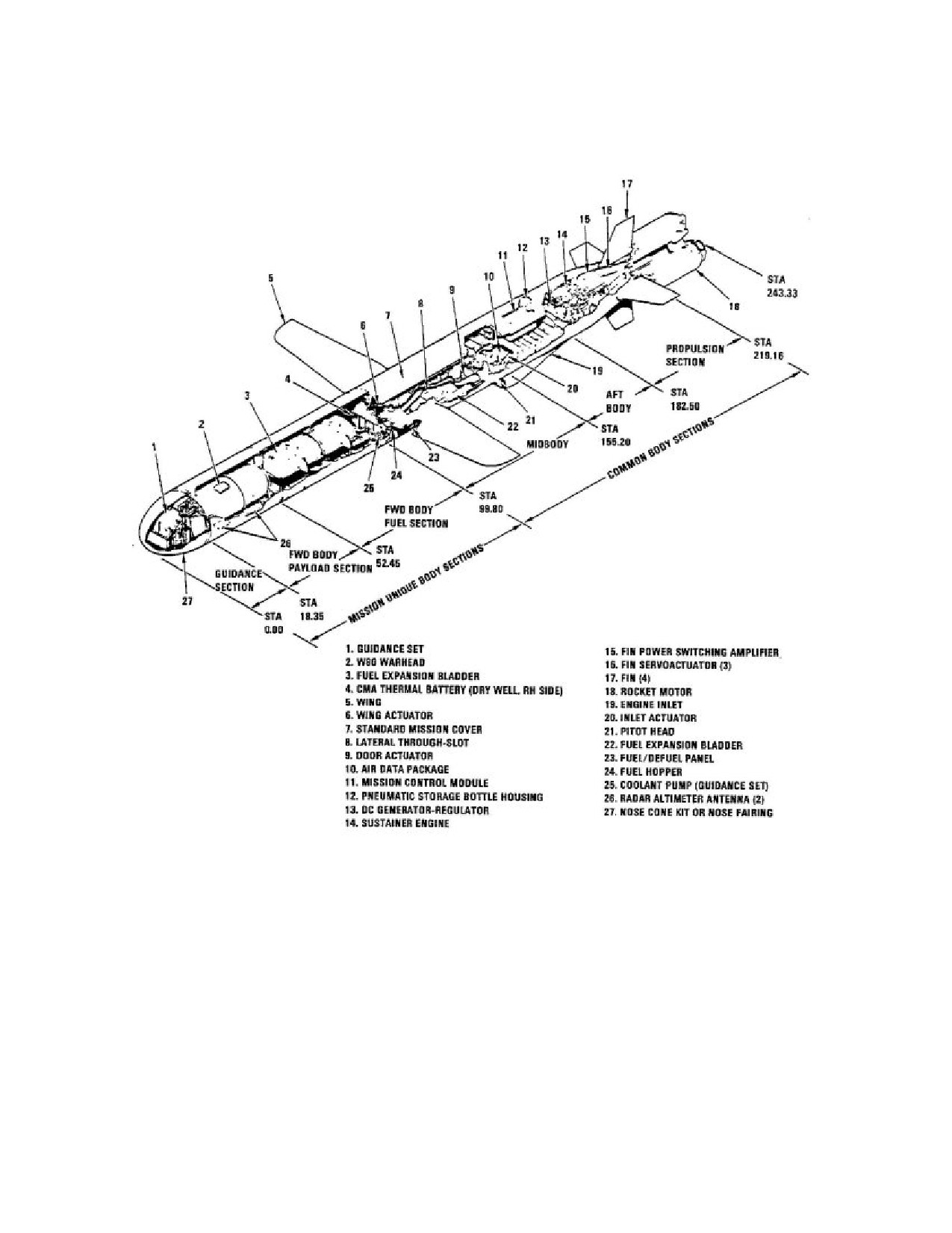
SW820-AP-MMI-010
REVISION 15
27 MARCH 2009
CHAPTER 1
Figure 1-1. Land-Attack 109A
61

SW820-AP-MMI-010
REVISION 15
27 MARCH 2009
CHAPTER 1
Figure 1-2. Cruise Missile Guidance Set (CMGS)
62
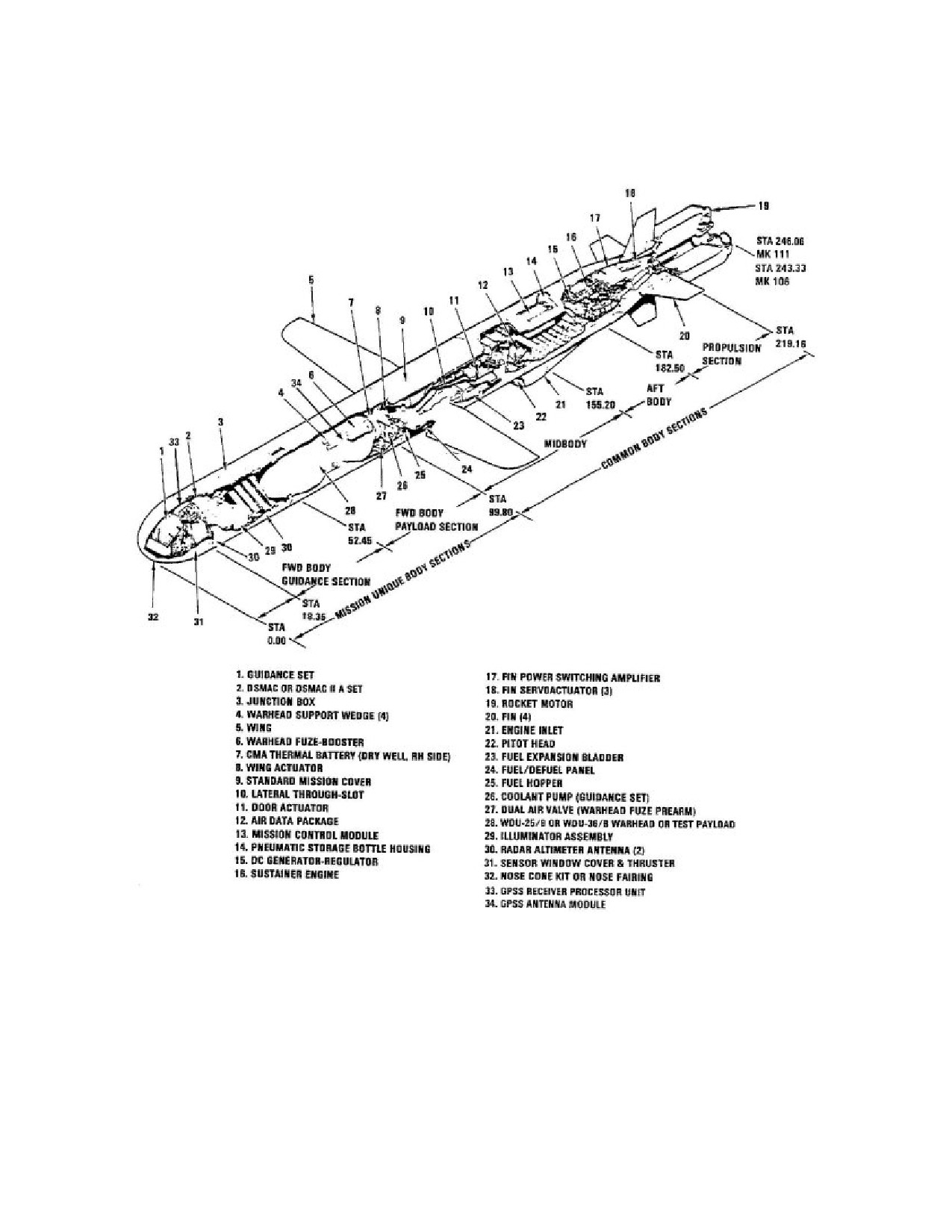
SW820-AP-MMI-010
REVISION 15
27 MARCH 2009
CHAPTER 1
Figure 1-3. Land-Attack 109C
63

SW820-AP-MMI-010
REVISION 15
27 MARCH 2009
CHAPTER 1
Figure 1-4. Digital Scene Matching Correlation
(DSMAC)
64

SW820-AP-MMI-010
REVISION 15
27 MARCH 2009
CHAPTER 1
Figure 1-5. Land-Attack 109D
65
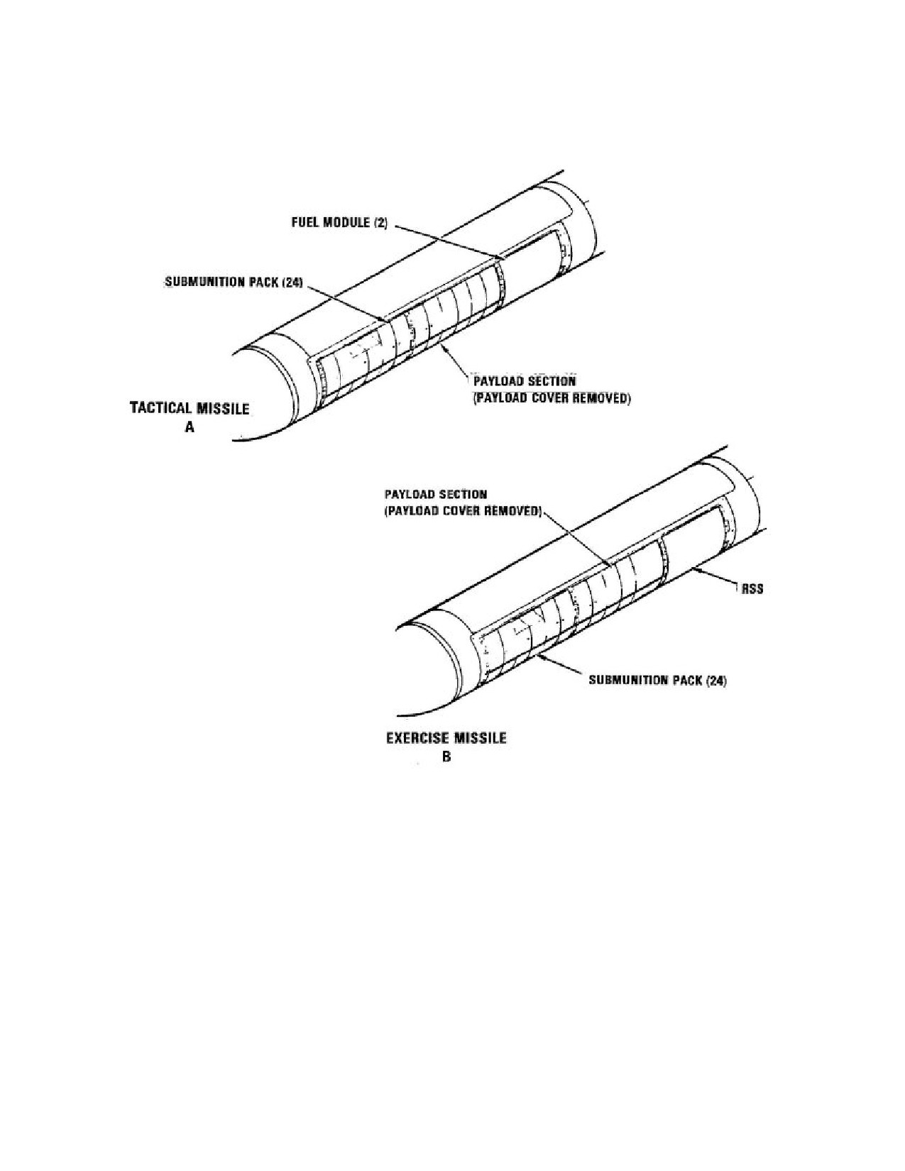
SW820-AP-MMI-010
REVISION 15
27 MARCH 2009
CHAPTER 1
Figure 1-6. Land-Attack 109D Payload Section
66

SW820-AP-MMI-010
REVISION 15
27 MARCH 2009
CHAPTER 1
Figure 1-7. Block IV Tactical TOMAHAWK Missile
General Arrangement
67