Military reference books and manuals (2009-2023, Volume 3) - page 21

Chapter 11: Current Unit Status
Unit Summary Tab
Figure 11-10: Current Location
3. Select the checkbox next to the desired location and click Save. The current location for the
selected unit will be updated. Optionally, you may select the User Supplied lat/long
checkbox to override the system lat/long coordinates associated with the selected location.
DRRS Software User Manual (SUM) 4.5.12
11-7

Unit Summary Tab
Chapter 11: Current Unit Status
DETACHMENT LOCATIONS
To enter detachment location information:
1. Click the Edit (pencil) icon next to Detachment Location(s).
Figure 11-11: Unit Deployment information
2. Enter the Location Code, Name, UIC, date, or lat/long coordinates of a detachment location
and click Search. The locations matching your criteria will be displayed.
3. Select the desired location from the search results and add it to the Current Detachment
Locations box using the arrow buttons between these two areas.
4. When finished adding locations, click Save. The unit detachment information is updated
and saved.
11.2.7
Blog
In the footer of each tab, the current version number of the CUS module is displayed. When
viewing a unit for which you are an Administrator, a button linking to the CUS Web Log (blog)
will also be displayed. The blog allows users to post messages that will be visible to other users
who will be able respond to those messages.
Figure 11-12: Tab Footer
11-8
DRRS Software User Manual (SUM) 4.5.12

Chapter 11: Current Unit Status
Unit Summary Tab
11.2.7.1
Accessing the CUS Blog
To access the CUS blog:
1. Click the Blog button in the footer of any tab.
Figure 11-13: CUS Blog
11.2.7.2
Post a New Blog Message
To post a new message:
1. Open the CUS Blog.
2. Click the Add Blog Message button.
Figure 11-14: CUS Blog Add Message
3. Enter a title and a message in the dialog that appears.
4. Click Submit when finished.
11.2.7.3
Respond to a Blog Message
To respond to an existing message:
1. Open the CUS Blog.
1. Click the Add link next to a message.
2. Enter a title and a message in the dialog that appears.
3. Click Submit when finished.
DRRS Software User Manual (SUM) 4.5.12
11-9

Unit Summary Tab
Chapter 11: Current Unit Status
11.2.7.4
Attach a File to a Blog Message
To attach a file to a blog message:
1. Open the CUS Blog.
2. Click the Attach (paperclip) icon next to a message.
Figure 11-15: CUS Blog
3. In the file attachment dialog, click Browse and select the file to be uploaded. You may
upload any Word, Excel, PowerPoint, PDF, or plain text document smaller than 4MB. Click
Save to return to the file attachment dialog when finished.
Figure 11-16: CUS Blog Attachments
4. Click Upload File and the file will be saved and attached to the selected message.
11-10
DRRS Software User Manual (SUM) 4.5.12

Chapter 11: Current Unit Status
METL Tab
11.3
METL Tab
The METL Tab allows the user to view ESORTS information without leaving the CUS
application. It contains the Mission Assessment, Build METL, and Office Management tabs.
Figure 11-17: CUS METL Tab
As mentioned at the beginning of this chapter, it is assumed that users have a working
knowledge of ESORTS before accessing CUS, therefore, the specifics of using the METL tab
will not be explained in this chapter. For details on how to perform ESORTS functions, refer to
Chapter 6: About ESORTS, Chapter 7: Setting Up ESORTS, Chapter 8: Mission Management,
Chapter 9: Build METL, and Chapter 10: Mission Assessment.
DRRS Software User Manual (SUM) 4.5.12
11-11
Personnel Tab
Chapter 11: Current Unit Status
11.4
Personnel Tab
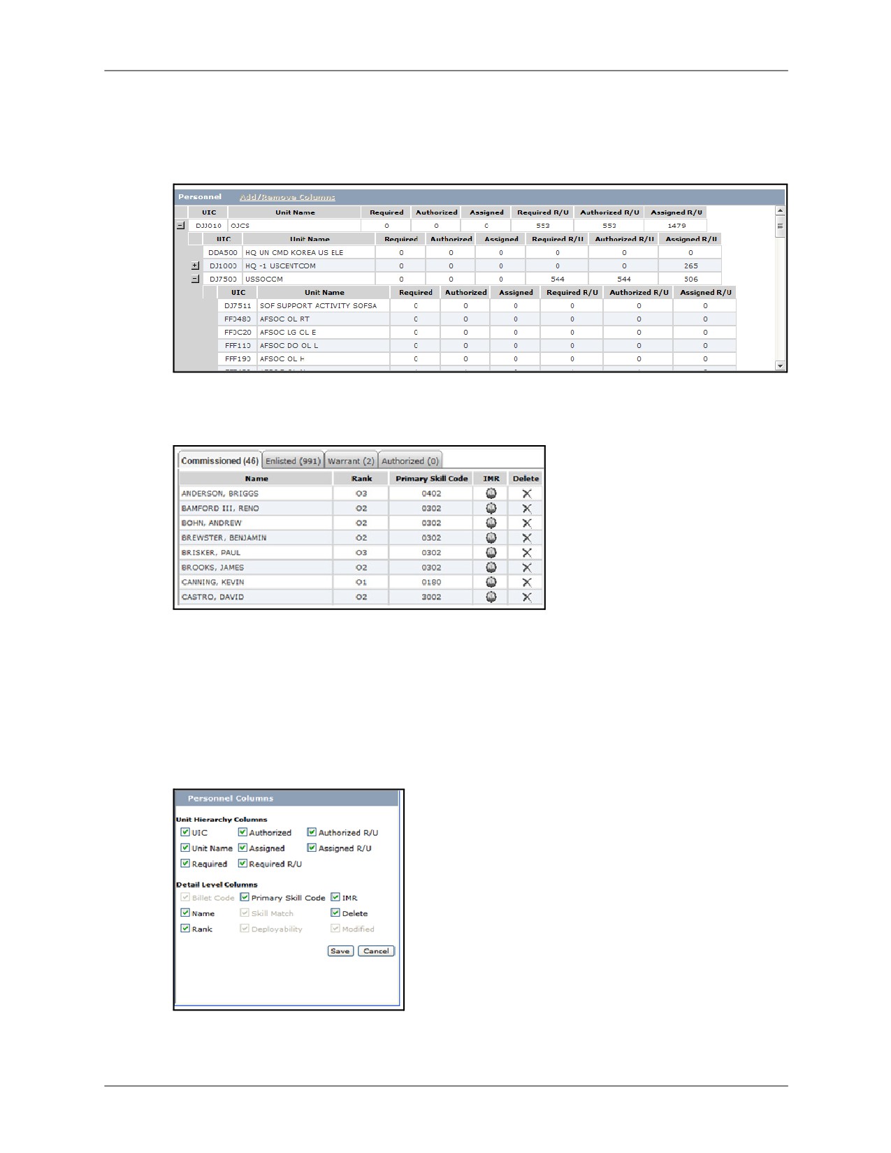
The Personnel Tab provides a roll-up view of the personnel status of a unit. You can click the
plus/minus sign next to a unit name to expand/collapse the view of its subordinate units.
Figure 11-18: Personnel Tab
Selecting a unit in this tab will populate the personnel details tab with the specific personnel
being reported for the selected unit.
Figure 11-19: Personnel Details
The Personnel Tab also provides the ability to export the displayed information to Excel or Word
by clicking the corresponding icon located just above the tab. You will be given the ability to
select different options for the exporting of the details.
11.4.1
Add/Remove Columns
Click the Add/Remove Columns link displays a dialog displaying Unit Hierarchy and Detail Level
Columns. Modify columns displayed by selecting check boxes.
Figure 11-20: Add/Remove Columns
11-12
DRRS Software User Manual (SUM) 4.5.12

Chapter 11: Current Unit Status
Personnel Tab
11.4.2
Adding Personnel
Clicking the Add Personnel button brings up a dialog allowing you to search for and assign
personnel to the selected unit. To do so:
1. Click Add Personnel.
Figure 11-21: Personnel Tab Footer
2. Enter all or part of the first name, last name, rank, or MOS to be added and click Search.
Figure 11-22: Add Personnel
3. Select the checkbox next to the results to be added to the selected unit and click Add
Selected.
The selected units are added to the unit and the personnel details are updated accordingly.
11.4.3
Reassigning Personnel
The Personnel tab provides the ability to reassign personnel, but only from your Primary Unit of
Assignment to any of its subordinate units. To do so:
1. Click the Reassign Personnel button.
Figure 11-23: Personnel Reassign
2. Select the checkboxes next to the personnel you wish to move.
DRRS Software User Manual (SUM) 4.5.12
11-13
Personnel Tab
Chapter 11: Current Unit Status
3. Select the unit to assign the personnel to.
4. Click Apply Changes.
Note: The following rules apply to reassigning personnel:
1.
You must be in personnel’s primary UIC.
2.
You must have CDR or Admin role.
3.
You can only assign a higher unit to a lower unit.
4.
If you need to assign back to the original unit (lower to higher) you must use the Add Personnel button.
11.4.4
Unit Locations
The Unit Locations button provides the same information and functionality as described in the
Unit Summary tab section.
11-14
DRRS Software User Manual (SUM) 4.5.12
Chapter 11: Current Unit Status
Equipment Tab
11.5
Equipment Tab
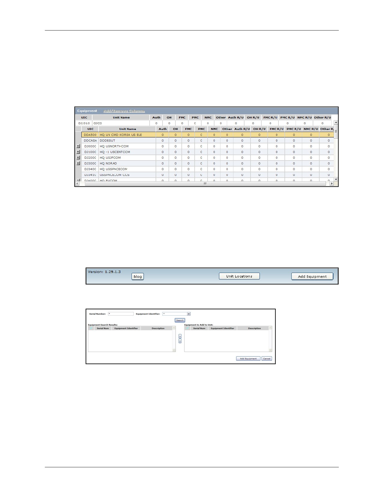
Much like the Personnel Tab, the Equipment Tab provides a roll-up view of the equipment
status of a unit and all of its associated subordinate units. Click the plus/minus signs next to a
UIC to expand/collapse the details of the equipment for that unit. The Equipment Tab also
provides the ability to export the displayed information to Excel or Word by clicking on the
corresponding icon located just above the tab. You will be given the ability to select whether to
include the entire hierarchy and/or equipment details.
Figure 11-24: Equipment Tab
Selecting a unit in this tab will populate the equipment details tab with the specific equipment
being reported for the selected unit.
11.5.1
Adding Equipment
Clicking the Add Equipment button brings up a dialog allowing you to search for and assign
personnel to the selected unit. To do so:
1. Click Add Equipment.
Figure 11-25: Equipment Tab Footer
2. Enter the serial number to be added or select an equipment identifier and click Search.
Figure 11-26: Add Equipment
3. Select the checkbox next to the results to be added to the selected unit and use the arrow
buttons to add them to the Equipment to Add to Unit box.
DRRS Software User Manual (SUM) 4.5.12
11-15

Equipment Tab
Chapter 11: Current Unit Status
11.5.2
Reassigning Equipment
The Equipment tab also provides the ability to reassign equipment from your Primary Unit of
Assignment to any of its subordinate units. To do so:
1. Click the Reassign Equipment button.
Figure 11-27: Equipment Reassign
2. Select the checkbox(es) next to the equipment you wish to move.
3. Select the unit to assign the equipment to.
4. Click Apply Changes.
11.5.3
Unit Locations
The Unit Locations button provides the same functionality as that described in the Unit
Summary tab.
11-16
DRRS Software User Manual (SUM) 4.5.12

Chapter 11: Current Unit Status
Training Tab
11.6
Training Tab
The Training Tab provides a view of the selected unit’s training status including readiness
rating, METs impacting the training, and percent of training completed.
Figure 11-28: Training Tab
To edit the training readiness level, click the Edit (pencil) icon. Modify the training information in
the popup that appears and click Save.
11.6.1
Adding Training
User administrators are able to add training for their primary units of assignment by using the
Add Training button which will be visible at the bottom of the tab.
To add training:
1. Click the Add Training button.
Figure 11-29: Training Tab Footer
2. Enter a description of the training area, the name of the exercise or course, completion
date, score achieved, and degradation date.
Figure 11-30: Add Training
3. Click Save when finished and the training information for the selected unit will be updated
with the information you entered.
DRRS Software User Manual (SUM) 4.5.12
11-17

ART Tab
Chapter 11: Current Unit Status
11.7
ART Tab
The ART tab provides easy access to the AEF Reporting Tool. Click the ART tab to open ART in
a separate window.
Figure 11-31: ART Application
11-18
DRRS Software User Manual (SUM) 4.5.12
Chapter 11: Current Unit Status
Top Concerns, Deficiencies, Lessons Learned Tabs
11.8
Top Concerns, Deficiencies, Lessons Learned Tabs
Users with JFRR permission for their units of interest will see these tabs when navigating to
their CUS page. Here are brief descriptions of these tabs. For more on these tabs, see Chapter
12: Readiness Dashboard (JFRR).
11.8.1
Top Concerns Tab
The Top Concerns Tab provides a view of Top Concerns, Deficiencies, and Lessons Learned
for a user’s unit. This tab allows users to enter all major areas of concern that the organization
has with supporting the JFRR scenario.Once these are entered by each of the Service, CSA,
and COCOM representatives, the Joint Staff can review and then export these concerns for the
JFRR.
11.8.2
Deficiencies Tab
The deficiencies tab allows organizations to provide justification describing any current
requirements not being met, quantified shortfall, operational impact, actions attempted to
alleviate/mitigate the shortfall, and what actions are required to improve the situation. Once
these deficiencies are entered by the Services, CSAs, and COCOMs, the Joint Staff can view
and manage them accordingly.
11.8.3
Lessons Learned Tab
The Lessons Learned tab allows users associated with a specific organization and assigned the
role of Unit Commander or Unit Administrator to collect and report on information from previous
and current missions. The information on this tab is viewable by the Joint Staff and is used to
avoid repeating mishaps.
DRRS Software User Manual (SUM) 4.5.12
11-19
Top Concerns, Deficiencies, Lessons Learned Tabs
Chapter 11: Current Unit Status
This Page Intentionally Left Blank.
11-20
DRRS Software User Manual (SUM) 4.5.12
PART V:
Force Management
This Page Intentionally Left Blank.
Chapter 12: Readiness Dashboard (JFRR)
Chapter 12: Readiness Dashboard (JFRR)
The Readiness Dashboard tool is used by several different roles, each one with slightly different
access and responsibilities: Services, CSAs, Functional COCOMs, Geographic COCOMs, and
Joint Staff. This chapter describes the use of the Readiness Dashboard in a step-by-step format
but since not all sections apply to each role, each section will state which roles it applies to. See
Section 12.3: Readiness Dashboard Workflow for more information.
This chapter consists of the following topics:
• JFRR Overview
• Readiness Dashboard Purpose
• Readiness Dashboard Workflow
• Accessing Readiness Dashboard
• View METL
• Top Concerns
• Deficiencies
• Lessons Learned
• JCCA Products
• JCCA Admin
• IPL
• Overall Assessment
• Summary
DRRS Software User Manual (SUM) 4.5.12
12-1
JFRR Overview
Chapter 12: Readiness Dashboard (JFRR)
12.1
JFRR Overview
Readiness Dashboard is a module supporting the Joint Forces Readiness Review (JFRR),
which is defined as follows:
“4.3.2. The JFRR shall conduct timely, scenario-based readiness assessments on a
quarterly basis. These assessments shall identify capability shortfalls and risks in
executing missions as assigned by the Secretary of Defense and will identify appropriate
measures to reduce these risks. The joint review shall employ modern analytic tools and
models, as appropriate, to aid in scenario assessment. The findings of the JFRR will be
reported to the SROC.”1
Title 10: Sec. 117 requires the Chairman of the Joint Chiefs of Staff to conduct a quarterly
review of the current level of readiness and capability of the Department to carry out their
wartime missions. The Joint Forces Readiness Review (JFRR) process supports this
requirement, providing a view of the following:
• Current readiness to execute assigned missions
• Projected readiness over next 12 months
• Scenario Assessment
• Top Two Concerns
• Readiness Summary and Trends
The JFRR normally evaluates two NMS scenarios each calendar year based on the reporting
guidance message.
• Initial JFRR Scenario Assessment: All supporting COCOMs, Services, and CSAs
report per the reporting guidance message. The supporting COCOMs, Services, and
CSAs assess Current, and Current +12 Months readiness, based on the specified "as
of" date(s).
An overall information briefing is developed by Joint Staff (J-3 Readiness), based on the
submitted JFRR reports and Service briefs.
Note: The reporting guidance message will clearly articulate the scenario, JFRR reporting timeline, the
reporting "as of" date, and any other specific guidance.
• Subsequent JFRR Scenario Assessment: All supported COCOMs, Services, and
USSOCOM report in the subsequent JFRR. The scenario timeline and “as of” date will
be specified in the reporting guidance message.
Supported UCCs (Unified Combatant Commands) prepare their reports and scenario
assessments taking into consideration the reports and results from the initial JFRR.
Joint Staff develops an updated information briefing, and any new issues and shortfalls
are again analyzed during a feedback process.
This process completes the JFRR. “Quarterly” results from this two-part JFRR process
occurring two times per year. However, the briefing is often reviewed and updated on a monthly
basis.
1.DODD 7730.65 “Department of Defense Readiness Reporting System (DRRS)”, June 3, 2002.
12-2
DRRS Software User Manual (SUM) 4.5.12
Chapter 12: Readiness Dashboard (JFRR)
Readiness Dashboard Purpose
12.2
Readiness Dashboard Purpose
The primary purpose of the Readiness Dashboard tool is to create a full report (MS Excel, MS
PowerPoint, and by viewing the DRRS application) which links readiness and resources, within
the context of missions, to determine which units and organizations possess the capability to
carry out the JFRR-assigned NMS-scenarios.
All current and projected mission readiness values are sourced from the ESORTS Mission
Assessment database. All ESORTS mission categories are displayed (Core, Major Plan, JCA,
Named Operation, Navy Mission, and Army Mission). Additionally, all ESORTS mission types
are displayed (JTF, CCMRF, CFC, and State).
In addition to displaying near real-time mission data, the Readiness Dashboard tool allows each
COCOM and CSA to input their top concerns, deficiencies, and overall assessment for the
representative missions, communicate with other users from the same organization, or
communicate directly with Joint Staff. This allows for direct insertion of issues/solutions to
address specific readiness shortfalls or short-term deficiencies in mission capability. This report
is saved on the system directly. Additionally, the Services detail their top concerns.
This report presents a solid picture for Joint Staff to complete the JFRR process within the
Readiness Dashboard tool. Joint Staff has their own area that automatically rolls-up all
COCOM, Service, and CSA reports. Joint Staff also makes recommendations on accepting new
deficiencies and proposed actions to mitigate risk.
Depending on your user privileges, this feature might not appear in your menu. This feature is currently
accessible by Joint Readiness users for purposes of product improvement. The following roles have the
ability to access the Readiness Dashboard tool:
• Joint Readiness User: read-only access
• Joint Readiness Editor: ability to enter details for all COCOM, CSA, or Service.
• Joint Staff Editor: ability to enter details for all
In addition, there is a Joint Readiness Administrator role with the responsibility to configure the Readiness
Dashboard tool with ESORTS. For information on this role, please see the “DRRS Software
Administration Manual (SAM)”
DRRS Software User Manual (SUM) 4.5.12
12-3

Readiness Dashboard Workflow
Chapter 12: Readiness Dashboard (JFRR)
12.3
Readiness Dashboard Workflow
The Readiness Dashboard tool supports the workflow of the JFRR process. Each organization
is allowed to enter details independently. At the conclusion of this assessment process, all
details roll-up to the Joint Staff area for the mitigation and report preparation process.
The following graphic illustrates this process in detail.
Figure 12-1: Readiness Dashboard Workflow
The following sections detail each organizations role (similar process workflows are combined
for the sake of brevity).
12-4
DRRS Software User Manual (SUM) 4.5.12

Chapter 12: Readiness Dashboard (JFRR)
Accessing Readiness Dashboard
12.4
Accessing Readiness Dashboard
To access the Readiness Dashboard map, select Force Management | Readiness
Dashboard from the Main Menu.
Figure 12-2: Readiness Dashboard Main Window
You must have one of the following user roles to access Readiness Dashboard:
Joint Readiness User, Joint Readiness Editor, or Joint Staff Editor.
To go directly to the readiness dashboard for an organization, select it from the Main menu. For example,
Force Management | Readiness Dashboard | Services | US Navy
will open the Navy’s
readiness dashboard directly.
The Readiness Dashboard map contains several tools:
A. READINESS DASHBOARD TOOLBAR
The Readiness Dashboard toolbar provides a set of tools that allow you to quickly export and
save information from the Readiness Dashboard tabs.
Figure 12-3: Readiness Dashboard Toolbar
The tools, from left to right, are:
• Export to PowerPoint: Exports the contents of the currently displayed tab (except
METL tab) to a PowerPoint presentation.
• Export to Excel: Exports the contents of the currently displayed tab (except METL tab)
to an Excel spreadsheet.
• Export to Word: Exports the contents of the currently displayed tab (except METL tab)
to a Word document.
• Snapshot Viewer: Opens the Summary tab, where you can view and compare your
“snapshots”.
DRRS Software User Manual (SUM) 4.5.12
12-5

Accessing Readiness Dashboard
Chapter 12: Readiness Dashboard (JFRR)
• Snapshot Capture: Captures the current status of the currently viewed organization’s
JFRR information for later viewing.
• Print: Prints the contents of the currently displayed tab.
• Home: Returns to the Readiness Dashboard map.
B. SELECTED ITEM INDICATOR
Displays the name of the organization currently selected. This is also the organization that will
be displayed in the readiness details area.
C. READINESS DASHBOARD MAP
The global map interface separates the geographic COCOMs by their specific areas of interest.
Each of the COCOMs is represented here by their seal with the Joint Staff seal at the top-middle
of the map. Clicking on any of these seals will select that organization and display its mission
details in the readiness details area.
D. ADDITIONAL ORGANIZATIONS
Hover over one of the three links the bottom-left corner of the map (Functional Commands,
Combat Support Agencies, Services) to display the corresponding organization’s seals which
provide the same functionality as those of the geographic COCOMs.
E. READINESS DETAILS
Click any of the seal icons to display the current missions corresponding to this CSA, Service,
COCOM, or Joint Staff in the Readiness Details box in the upper-right corner.
F. READINESS DASHBOARD LINK
Click the selected organization’s seal at the top of the Readiness Details box to open that
organization’s Readiness Dashboard.
G. MISSIONS
The missions associated with the selected organization and their associated current (CUR) and
projected (PRJ) assessment values are displayed here.
Figure 12-4: Readiness Dashboard: Select Icon
12-6
DRRS Software User Manual (SUM) 4.5.12

Chapter 12: Readiness Dashboard (JFRR)
Accessing Readiness Dashboard
Note the difference between the readiness value displayed on the map versus the values
displayed in the Readiness Details. The halo on the map represents the lowest mission
assessment entered in the Readiness Dashboard tool while the Readiness Details box displays
the ESORTS Mission Assessment readiness value for each mission individually.
Hovering over any of the readiness value icons will display the date of the commander’s last manual
Overall Mission Assessment update and any associated comments for that mission.
H. VIEW ALL MISSIONS
Another display option is to click the link at the bottom of the screen to view all geographic
COCOM missions in list format. This is useful when trying to find a specific mission or
comparing the COCOM assessments quickly. Clicking on a COCOM’s name will navigate to the
corresponding readiness dashboard while clicking on any mission will open the Capability Trees
module.
Figure 12-5: All Missions Display
I. LEGEND
All of the seals on the map and in the additional orgs section have a colored border, called a
halo, that represents the value of the lowest JFRR Overall Mission Assessment rating within
that organization’s assigned missions. This rating is the manual assessment performed by the
head of the selected organization. The color definitions are provided in the legend at the bottom
of the readiness dashboard map and are as follows:
• Green: ESORTS value “Yes”
• Yellow: ESORTS value “Qualified Yes”
• Red: ESORTS value “No”
• Grey: Not Reporting (no manual assessments performed)
Some seals will also have a blue arrow next to them pointing either up or down. This denotes
that a commander override assessment was entered for that organization. A commander
override is an assessment value representing that organization’s commander’s assessment of
overall readiness despite existing ESORTS indications.
DRRS Software User Manual (SUM) 4.5.12
12-7

View METL
Chapter 12: Readiness Dashboard (JFRR)
12.5
View METL
CSAS, FUNCTIONAL COCOMS, GEOGRAPHIC COCOMS
The readiness dashboard provides a view of the ESORTS Mission Essential Task List for a
selected organization. To utilize this function:
1. Access the desired CSA or COCOM’s Readiness Dashboard. By default, the METL tab is
selected. Each CSA reports on its ability to perform assigned missions as well as specific
agency tasks to a prescribed standard under set conditions. The METL tab displays these
ESORTS assessments in near real-time. For more information, you can select the Y, Q, or N
that display under each mission name to display ESORTS Mission Assessment comments.
Figure 12-6: View METL Tab
The METL viewer features the same basic functionality as the standard ESORTS mission
assessment tool.
For more information on using the ESORTS assessment tools, please see Chapter 10: Mission
Assessment.
12-8
DRRS Software User Manual (SUM) 4.5.12

Chapter 12: Readiness Dashboard (JFRR)
Top Concerns
12.6
Top Concerns
The Top Concerns tool allows users to enter all major areas of concern that the organization
has with supporting the JFRR scenario. Once these are entered by each of the Service, CSA,
and COCOM representatives, the Joint Staff can review and then export these concerns to for
the JFRR.
12.6.1
Enter Top Concerns
SERVICES, CSAS, FUNCTIONAL COCOMS, GEOGRAPHIC COCOMS
To enter top concerns:
1. Access the desired Service, CSA, or COCOM’s Readiness Dashboard.
2. Open the Top Concerns tab.
Figure 12-7: Top Concerns
3. Click the Add button in the Top Concerns panel or the Current and Projected Overall panel.
Figure 12-8: Add Top Concern
4. Enter the title of the concern in the Title field. This will ultimately be displayed as a bullet
item when exported. If necessary, attach a file explaining this concern in more detail.
5. Click Save. The page refreshes and the concern is displayed in the Top Concerns table.
6. Click the Add Comment button (the green plus sign) corresponding to your newly entered
concern to add a comment, such as a more detailed description, for that concern. Click
Save and the Top Concerns pages will update to reflect your changes. You may enter
multiple comments for the same concern in this fashion.
7. Enter additional concerns (if applicable) following the same procedure. When complete, the
concerns are displayed in the order in which they were entered, with the first entered at the
top.
8. Set the priority order of the concerns, moving the concerns up or down by using the blue
priority arrows. This will determine the order of the concerns when displayed in the exported
output.
DRRS Software User Manual (SUM) 4.5.12
12-9

Top Concerns
Chapter 12: Readiness Dashboard (JFRR)
9. Click the Save Priority button to set the priority.
10. Click the View Subordinates button to view top concerns for Subordinate units. (Add your
unit as a subordinate to a group called Subordinates using Group Builder.)
12-10
DRRS Software User Manual (SUM) 4.5.12
Chapter 12: Readiness Dashboard (JFRR)
Deficiencies
12.7
Deficiencies
The deficiencies tab allows organizations to provide justification describing any current
requirements not being met, quantified shortfall, operational impact, actions attempted to
alleviate/mitigate the shortfall, and what actions are required to improve the situation. Once
these deficiencies are entered by the Services, CSAs, and COCOMs, the Joint Staff can view
and manage them accordingly.
12.7.1
Add Deficiencies
SERVICES, CSAS, FUNCTIONAL COCOMS, GEOGRAPHIC COCOMS
To enter deficiencies associated with the JFRR mission:
1. Access the desired Service, CSA, or COCOM’s Readiness Dashboard.
2. Open the Deficiencies tab.
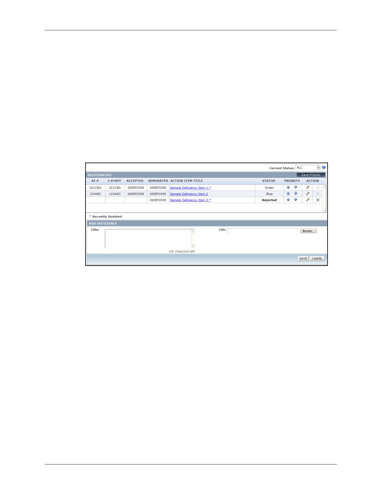
Figure 12-9: Deficiencies
3. Enter a title and attach a file that provides the necessary description of your new deficiency.
Both are required.
4. Click Add.
5. Add additional deficiencies as needed following the same procedure.
6. Set the priority order of the deficiencies, moving them up or down by using the blue priority
arrows. This will determine the order of the concerns when in the exported output.
7. Click Save Priority when finished.
All deficiencies are in nominated status until the Joint Staff reviews them. There are two
possible outcomes from this review. If accepted by Joint Staff, an action item number (AI# ),
point of contact, and date are assigned to the deficiency. Additionally, the status will change to
one of the following:
• Red: Acknowledged risk
• Yellow: Fix outside two years
• Green: Fix inside two years
• White: Formal study required
• Grey: Joint Staff review still in-progress
• Blue: Change ends or ways
DRRS Software User Manual (SUM) 4.5.12
12-11
Deficiencies
Chapter 12: Readiness Dashboard (JFRR)
If rejected by Joint Staff, the status will change to “Rejected”. Click the hyperlinked status to
view the reason for rejection. You may not delete a deficiency once its status has been changed
from “Nominated”. You can, however, update the deficiency at any time by accessing the Edit
tool (pencil icon). The deficiency will be marked with an asterisk, signaling that it has been
modified and should be reviewed by Joint Staff, but the status will remain “Rejected”. Joint Staff
members may edit the status of a deficiency or delete it. If they return the status to “Nominated”,
the deficiency can be edited and resubmitted by the owning organization. If the Joint Staff
deletes a deficiency, that deficiency is removed from their view and may now be deleted by the
owning organization as well. Until that point, it will still be visible in the owning organization’s
Deficiencies tab.
12.7.2
Manage Deficiencies
JOINT STAFF
For Joint Staff, the deficiencies tab displays a roll-up of every CSA-, Service-, and COCOM-
entered deficiency in a single view. There are four functions that can be performed on this page:
• Approve or Reject Deficiencies: Allows Joint Staff to review each deficiency and
decide whether to approve, close, or reject.
• Combine Deficiencies: Multiple organizations may have a common set of deficiencies
that may be combined into a single deficiency.
• Delete Deficiencies: Deficiencies in the Closed, Rejected, or Nominated status may be
deleted by Joint Staff or by the command that submitted them. When the Joint Staff
deletes a deficiency, it is removed from all Joint Staff views and set to “JS Deleted”
status. It will still be visible in the submitting command’s view, however, until they delete
it themselves. If the command that submitted a deficiency initiates the deletion, the
deficiency is completely removed from the system including Joint Staff views.
• Set Priority Order: Joint Staff can set the final priority order of all deficiencies.
12.7.2.1
Approve or Reject Deficiencies
1. Access the Joint Staff Readiness Dashboard.
2. Open the Deficiencies tab.
3. Review the available deficiencies. All new tasks will have a status of “Nominated” while all
updated tasks will be marked with an asterisk. You may filter the display by organization
using the Command drop-down menu or by deficiency status using the Status drop-down
menu. By clicking the hyperlinked text in the Command column, you can review any
attachments if applicable.
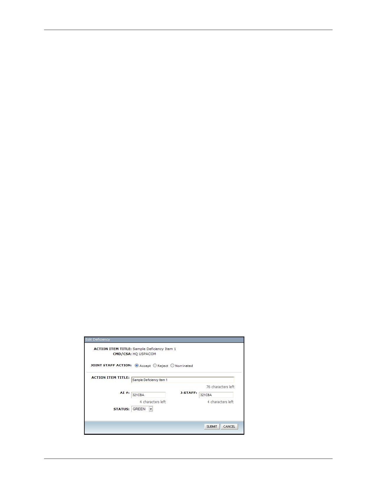
4. Click Edit (pencil icon) for the item you would like to approve or reject.
Figure 12-10: Edit Deficiency
12-12
DRRS Software User Manual (SUM) 4.5.12

Chapter 12: Readiness Dashboard (JFRR)
Deficiencies
5.
To approve a deficiency, select the Accept radio button and enter the following:
• Action Item number (AI#) - Enter up to 10 characters.
• Joint Staff name (J-Staff) - Enter up to 10 characters.
• Status - Select from the following values:
•
Accepted: Deficiency accepted by Joint Staff.
•
All: Show all deficiencies.
•
Blue: Change ends or ways.
•
Closed: Joint Staff has closed the request.
•
Green: Fix inside two years.
•
Grey: Joint Staff review still in-progress.
•
Nominated: Newly created deficiency, awaiting approval.
•
Red: Acknowledged risk.
•
Rejected: Joint Staff did not approve. Sent back to originator for update or outright
rejection.
•
White: Formal study required.
•
Yellow: Fix outside two years.
6.
Click Save when finished. The deficiency status and details are updated and can be seen
by the owning organization who will still be able to modify the deficiency. If they do so, you
will see an asterisk in the Command column next to that organization’s name at which point
the deficiency should be reviewed and the status/details changed as necessary.
You may return to an approved deficiency at any time and either edit the details or change
the status using the Edit button.
7.
To reject a deficiency, select the Reject radio button, enter a reason for the rejection, and
click Save. The status will be updated and the corresponding organization will be able to
view the rejection reason you entered. They will also still be able to modify the deficiency. If
they do so, you will see an asterisk in the Command column next to that organization’s
name at which point the deficiency should be reviewed and the status/details changed as
necessary.
Figure 12-11: Reject Deficiency
You may return to a rejected deficiency at any time and either edit the rejection reason or
change the status using the Edit button.
DRRS Software User Manual (SUM) 4.5.12
12-13

Deficiencies
Chapter 12: Readiness Dashboard (JFRR)
8. A deficiency may also be returned to the “Nominated” status at any time. This provides the
owning organization with the ability to delete the deficiency.
12.7.2.2
Combine Deficiencies
Combining similar deficiencies allows the Joint Staff user to combine two or more related
deficiencies from any organization. They can still be edited individually by the owning
organizations.
Selected deficiencies do not have to share the same status to be combined, however, they must
all have a status other than “Nominated” or “Rejected”.
To combine deficiencies:
1. Access the Joint Staff Readiness Dashboard.
2. Open the Deficiencies tab.
3. Click Combine Deficiencies.
Figure 12-12: Joint Staff Deficiencies Tab
4. Select the Combine radio button (if necessary).
Figure 12-13: Combine Deficiencies Menu
5. Find the deficiencies you would like to combine and click the corresponding checkbox for
each. You may use the Command and Current Status filters to find help you find them.
6. Enter a title, AI#, J-Staff name, and status for your combined deficiency. This information
will be applied to all of the associated deficiencies.
7. Click Save. The selected deficiencies will display as a single item. You may still access the
attached files by clicking the corresponding organization’s name from the Command
column.
12-14
DRRS Software User Manual (SUM) 4.5.12

Chapter 12: Readiness Dashboard (JFRR)
Deficiencies
Figure 12-14: Combined Deficiency
12.7.2.2.1 Split a Combined Deficiency
The interface for combining deficiencies supports the ability to separate them as well. To do so:
1. Access the Joint Staff Readiness Dashboard.
2. Open the Deficiencies tab.
3. Click Combine Deficiencies.
4. Select the Edit/Separate radio button and the Combined List dropdown menu will appear
on the right. From it, choose the combined deficiency you would like to edit. When you do
so, the associated deficiencies will be displayed in the Deficiencies box below.
5. Uncheck the deficiencies you would like to remove from this combined deficiency. If you
would like to dismantle the entire combined deficiency, uncheck all the checkboxes.
Clicking the blank checkbox in the header column will toggle all checkboxes as selected or deselected.
6. Click Save. The selected deficiencies will be updated in the Joint Staff deficiency view. They
will retain the AI#, J-Staff, and status values given to them in the combined deficiency.
12.7.2.3
Delete Deficiencies
Deficiencies that are in the Closed, Rejected, or Nominated status can be deleted from the
deficiencies list. Both Joint Staff users and the command that submitted them have the power to
do this, however, only Joint Staff can delete combined deficiencies.
To delete a deficiency:
1. Access the Joint Staff Readiness Dashboard.
2. Open the Deficiencies tab.
3. Find the deficiency to be deleted. If necessary, filter the view using the Current Status
dropdown.
4. Click Delete (X icon) for the corresponding deficiency. You will be prompted to confirm the
deletion. Doing so will permanently remove the selected deficiency from the system.
12.7.2.4
Set Priority Order
Before finalizing the deficiencies, it is important that the list is arranged in the correct priority
order. To be able to do this, the Command and Current Status filters must be set to “All”. This
ensures that priority order changes are made in relation to the entire list.
To set priority order:
1. Access the Joint Staff Readiness Dashboard.
2. Open the Deficiencies tab.
3. Utilize the blue priority arrows to move deficiencies up or down in the list (priority ranking is
top to bottom).
DRRS Software User Manual (SUM) 4.5.12
12-15
Deficiencies
Chapter 12: Readiness Dashboard (JFRR)
4. Once the order has been modified as needed, click Save Priority.
12.7.2.4.1 View Subordinates
Click the View Subordinates button to Copy Lessons Learned. Click in the Group Name box to
select a group from the list and set group as your subordinates.
12-16
DRRS Software User Manual (SUM) 4.5.12

Chapter 12: Readiness Dashboard (JFRR)
Lessons Learned
12.8
Lessons Learned
The Lessons Learned tab provides a place for users of each COCOM, CSA, Service, or the
Joint Staff to post valuable information garnered from current or recent mission and JFRR
experiences. This tab provides a chance to avoid recurring errors. By posting key information
discovered throughout the course of an organization’s career, that organization’s team
members will have a central repository of useful information. Lessons posted in this tab will be
visible to Joint Staff users.
12.8.1
Add Lessons Learned
SERVICES, CSAS, FUNCTIONAL COCOMS, GEOGRAPHIC COCOMS, JOINT STAFF
To add a lesson learned:
1. Access the desired Service, CSA, COCOM, or Joint Staff Readiness Dashboard.
2. Open the Lessons Learned tab.
3. Click the Add button in the upper-right corner.
Figure 12-15: Lessons Learned Tab
4. Enter a title for your message and include an attachment providing further instruction or
detail.
Figure 12-16: Adding a Lesson Learned
5. Click Save. The message is added to the Lessons Learned tab for this selected
organization. The message can be modified at any time using the corresponding Edit
button (pencil icon) or deleted using the Delete button (“X” icon). Lessons may also be
commented upon by other users by clicking the Add Comment button (green “plus” sign),
entering a comment, and clicking the Save button.
DRRS Software User Manual (SUM) 4.5.12
12-17
Lessons Learned
Chapter 12: Readiness Dashboard (JFRR)
12.8.1.1
Set Priority Order
Before finishing the list of lessons learned, it is important that the list is arranged in the desired
order of priority.
To set the priority order:
1. Access the desired Service, CSA, COCOM, or Joint Staff Readiness Dashboard.
2. Open the Lessons Learned tab.
3. Utilize the blue priority arrows to move lessons up or down in the list (priority ranking is top
to bottom).
4. Once the order has been modified as needed, click Save Priority.
12.8.1.1.1 Click the View Subordinates button to Copy Lessons Learned. Click the Group Name box to
select a group from the list and set group as your subordinates.
12-18
DRRS Software User Manual (SUM) 4.5.12
Chapter 12: Readiness Dashboard (JFRR)
JCCA Products
12.9
JCCA Products
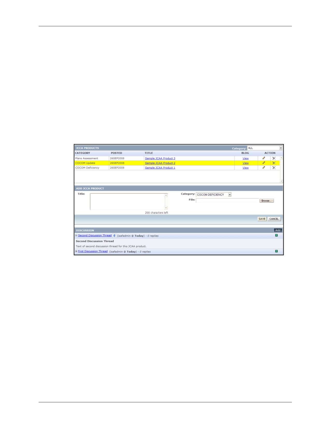
JCCA Products is a communication tool allowing Joint Staff to communicate with all
organizations through a system interface. Only Joint Staff Editors can create the initial JCCA
products, but all Readiness Dashboard users can see and respond to them via the JCCA
Products Blog tool.
12.9.1
Create JCCA Product
JOINT STAFF
To create a JCCA Product:
1. Access the Joint Staff Readiness Dashboard.
2. Open the JCCA Products tab.
3. Click the Add button in the JCCA Products box.
Figure 12-17: JCCA Products Main Screen
4. Enter a title for your product and include an attachment providing further instruction or
detail.
5. Click Save. The message is added to the JCCA Products box. The product can be modified
at any time using the corresponding Edit button (pencil icon) or deleted using the Delete
button (“X” icon).
DRRS Software User Manual (SUM) 4.5.12
12-19

JCCA Products
Chapter 12: Readiness Dashboard (JFRR)
12.9.2
Respond to JCCA Products
SERVICES, CSAS, FUNCTIONAL COCOMS, GEOGRAPHIC COCOMS, JOINT STAFF
To respond to a JCCA Product:
1. Access the desired Service, CSA, COCOM, or Joint Staff Readiness Dashboard.
2. Open the JCCA Products tab. It is important now to differentiate between the two boxes
contained in this tab. The top box is the JCCA Products box and contains the message titles
and document attachment. These are the original message and file added by the Joint Staff
Editor. The bottom box is the Blog box. It contains and manages all the responses to the
individual JCCA products.
To view the details of a product in the JCCA Products box, click the hyperlinked title and the
associated attachment for that message will open.
3. Once you have found a message you wish to respond to, click the corresponding View link
in the JCCA Products box to view the current responses for that message. Those
responses, if there are any, are displayed in the Blog box. If there are none, the box will
remain empty after you’ve clicked the View link.
Figure 12-18: JCCA Products Main Screen
4. To add a new blog response, click the Add button in the Discussion box.
5. Enter both a title for your message and the message itself in the Add Blog Message dialog.
When you are finished, click Save.
Figure 12-19: Add Blog Message (JCCA Products)
12-20
DRRS Software User Manual (SUM) 4.5.12

Chapter 12: Readiness Dashboard (JFRR)
JCCA Products
Your response to the selected JCCA product is visible to all Readiness Dashboard users
along with your user name and the creation date. Clicking the hyperlinked title of your
message will toggle the display of the body text.
6. Any user can then post a response to your blog message by clicking the Add hyperlink
under the Comment column of your message listing in the Blog box.
Figure 12-20: Blog Discussion
This response can be viewed by clicking the number hyperlink under the Replies column of
your message listing in the Blog box. It is this functionality that makes it possible for
organizations to simultaneously discuss ideas with Joint Staff.
DRRS Software User Manual (SUM) 4.5.12
12-21

JCCA Admin
Chapter 12: Readiness Dashboard (JFRR)
12.10
JCCA Admin
On the JCCA Admin tab, a Joint Staff user is able to add Joint Combat Capability Area (JCCA)
Admin information for Joint Staff as well as view and add discussion items and comments for
other commands. The JCCA Admin tab is also available to command users, providing visibility
to their command only. Other users can view JCCA Admin information here.
A DISCUSSION pane displays below the ADD JCCA ADMIN and JCCA ADMIN panes when at
least one JCCA Admin item has been entered.
Figure 12-21: JCCA Admin tab with Category drop down
12-22
DRRS Software User Manual (SUM) 4.5.12
Chapter 12: Readiness Dashboard (JFRR)
IPL
12.11
IPL
The Integrated Priority List (IPL) is a communication tool similar to the JCCA Products tool
except that the communication in it is unique to each organization. Unlike some of the other
tools described in this chapter, there is no roll-up of the data in IPL. Other organizations cannot
see the messages posted in your organization’s IPL page. This provides each organization’s
members a way to communicate and collaborate with each other more privately.
12.11.1
Create IPL Messages
SERVICES, CSAS, FUNCTIONAL COCOMS, GEOGRAPHIC COCOMS
To create an IPL Message:
1. Access the desired Service, CSA, or COCOM’s Readiness Dashboard.
2. Open the IPL tab.
3. Click the Add button in the Integrated Priority List box.
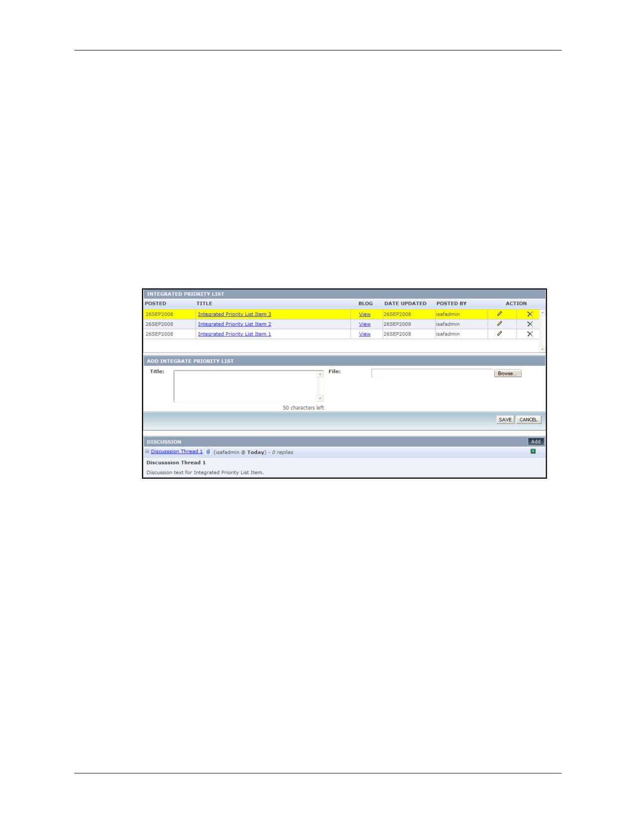
Figure 12-22: Integrated Priority List Main Screen
4. Enter a title for your message and include an attachment providing further instruction or
detail.
5. Click Save. The message is added to the Integrated Priority List box. The message can be
modified at any time using the corresponding Edit button (pencil icon) or deleted using the
Delete button (“X” icon).
12.11.2
Respond to IPL Messages
SERVICES, CSAS, FUNCTIONAL COCOMS, GEOGRAPHIC COCOMS
To respond to an IPL Message:
1. Access the desired Service, CSA, or COCOM’s Readiness Dashboard.
2. Open the IPL tab. It is important now to differentiate between the two message boxes
contained in this tab. The top box is the Integrated Priority List box and contains the
message titles and document attachment. These are the original message and file added by
the message initiator. The bottom box is the Blog box. It contains and manages all the
responses to the individual IPL messages.
To view the details of a message in the Integrated Priority List box, click the hyperlinked title
and the associated attachment for that message will open.
DRRS Software User Manual (SUM) 4.5.12
12-23
IPL
Chapter 12: Readiness Dashboard (JFRR)
3. Once you have found a message you wish to respond to, click the corresponding View link
in the Integrated Priority List box to view the current responses for that message. Those
responses, if there are any, are displayed in the Blog box. If there are none, the box will
remain empty after you’ve clicked the View link.
Figure 12-23: View Integrated Priority List Messages
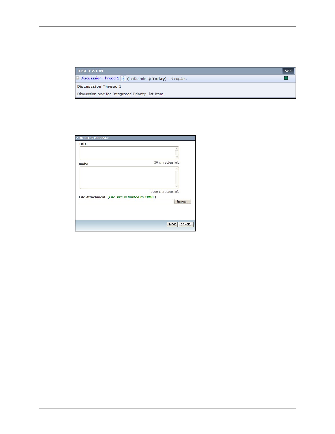
4. To add a new blog response, click the Add button in the Blog box.
5. Enter both a title for your message and the message itself in the Add Blog Message dialog.
When you are finished, click Save.
Figure 12-24: Add IPL Blog Message
Your response to the selected IPL message is visible to all other users of your organization
and contains your user name and the creation date. Clicking the hyperlinked title of your
message will toggle the display of the body text.
6. Any of these users can then post a response to your blog message by clicking the Add
hyperlink under the Comment column of your message listing in the Blog box.
This response can be viewed by clicking the number hyperlink under the Replies column of
your message listing in the Blog box. It is this functionality that makes it possible for users of
this organization to simultaneously discuss ideas with each other.
12-24
DRRS Software User Manual (SUM) 4.5.12

Chapter 12: Readiness Dashboard (JFRR)
Overall Assessment
12.12
Overall Assessment
12.12.1 Add Assessments
SERVICES, CSAS, FUNCTIONAL COCOMS, GEOGRAPHIC COCOMS
The Overall Assessment tool allows users to insert a subjective assessment of readiness
indicators for their organization. This readiness report is rolled-up for the Joint Staff report.
To add/edit an overall assessment:
1. Access the desired Service, CSA, or COCOM’s Readiness Dashboard.
2. Open the Overall Assessment tab. All related missions for the selected organization are
displayed in the Missions box along with their respective current and projected readiness
ratings.
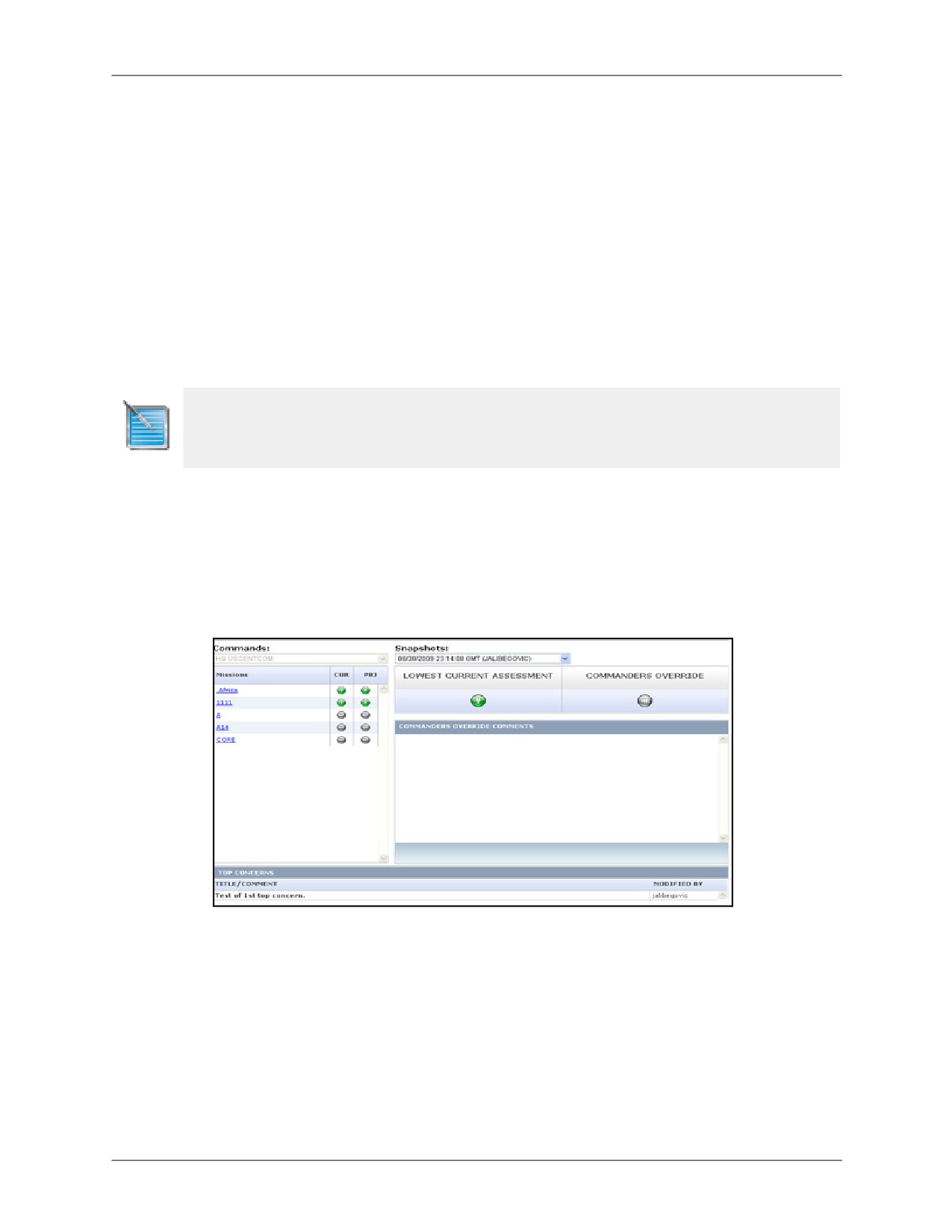
Figure 12-25: Overall Assessment
The right side of the screen contains the Overall Assessment box which displays the
Lowest Current Assessment rating from the list of missions. There is also a
Commander’s Override value that may be input to indicate the readiness capabilities
according to the responsible parties of an organization.
3. Click the Edit button in the Overall Assessment box.
Figure 12-26: View Updated Assessment
4. Select a new readiness value (Y/Q/N/NR) and enter detailed remarks in the Comments
field, being as specific as possible for the reasoning behind the override. The override value
must be different than the Lowest Current Assessment displayed in the Overall Assessment
box.
DRRS Software User Manual (SUM) 4.5.12
12-25
Overall Assessment
Chapter 12: Readiness Dashboard (JFRR)
5. Click Submit when finished and the assessment is saved.
On the readiness map, the color of the halo for this organization will be changed from the
Lowest Current Assessment value (in this case N/Red) to the Commander’s Override value
(Q/Yellow) value.
Figure 12-27: Relationship of Readiness Dashboard (left) to Commander’s Override (right)
Any change in status caused by the Commander’s Override is denoted by a blue arrow next
to an organization’s icon on the readiness map.
• If the Commander’s Override is greater than the Lowest Current Assessment value, a
Commander Upgrade is indicated by an upward pointing arrow.
• If the Commander’s Override is lower than the Lowest Current Assessment value, a
Commander Downgrade is indicated by a downward pointing arrow.
• If the Commander’s Override value is “Not Reported,” then any previously existing
assessment value indicator (up or down arrow) is removed from the readiness map.
To quickly access the Overall Assessment from the Readiness Dashboard, click the indicator arrow next
to an organization’s halo.
12-26
DRRS Software User Manual (SUM) 4.5.12
Chapter 12: Readiness Dashboard (JFRR)
Summary
12.13
Summary
The Summary tab, also known as the Snapshot Viewer, contains the current overview of the
selected organization as well as all of the saved snapshots for that organization.
12.13.1 Capturing a Snapshot
SERVICES, CSAS, FUNCTIONAL COCOMS, GEOGRAPHIC COCOMS, JOINT STAFF
To capture a snapshot:
1. Access the desired Service, CSA, or COCOM’s Readiness Dashboard. Navigate to any tab.
2. Click the Capture Snapshot button in the Readiness Dashboard Toolbar. The current Top
Concerns, Scenarios, Deficiencies, Unit Missions, and Overall Assessment for the selected
organization are saved for future viewing.
Joint Staff users have the ability to take snapshots of any organization’s information from the Joint Staff
Readiness Dashboard. This is accomplished by clicking the Capture Snapshot button.
12.13.2 Viewing Snapshots
SERVICES, CSAS, FUNCTIONAL COCOMS, GEOGRAPHIC COCOMS, JOINT STAFF
To view existing snapshots:
1. Access the desired Service, CSA, COCOM, or Joint Staff Readiness Dashboard.
2. Navigate to the Summary tab.
Figure 12-28: Summary Status Tab
3. Select a snapshot to view from the Snapshots dropdown menu. By default, Latest Summary
will be selected. This is the current status of the organization. Each snapshot will specify the
date and time it was taken at and by which user. Once a snapshot is selected, the tab will
display the information stored in that snapshot, providing you with an historical look at this
organization’s status. By viewing snapshots chronologically, one can track the progress of
their organization and its JFRR status.
Joint Staff users accessing the Joint Staff Readiness Dashboard will be able to utilize the
Commands dropdown, located next to the Snapshots dropdown, which allows them to
access the summary data from any of the other Readiness Dashboards without having to
navigate to another page. This field will be inactive for all other users.
DRRS Software User Manual (SUM) 4.5.12
12-27
Summary
Chapter 12: Readiness Dashboard (JFRR)
This Page Intentionally Left Blank.
12-28
DRRS Software User Manual (SUM) 4.5.12
Chapter 13: State Readiness Dashboard
Chapter 13: State Readiness Dashboard
The State Readiness Dashboard provides visibility into the readiness capability of each
individual state’s missions and scenarios. This is accomplished using a graphical representation
of those states that provides an at-a-glance readiness value and permits users to drill into the
details of each scenario or mission.
This chapter consists of the following topics:
• Accessing State Readiness Dashboard
• Dashboard Maps
• States Drill-Down
• State Capability Trees
DRRS Software User Manual (SUM) 4.5.12
13-1
Accessing State Readiness Dashboard
Chapter 13: State Readiness Dashboard
13.1
Accessing State Readiness Dashboard
To access State Readiness you must have the Joint Readiness Editor role. Select Force
Management | State Readiness Dashboard from the main menu.
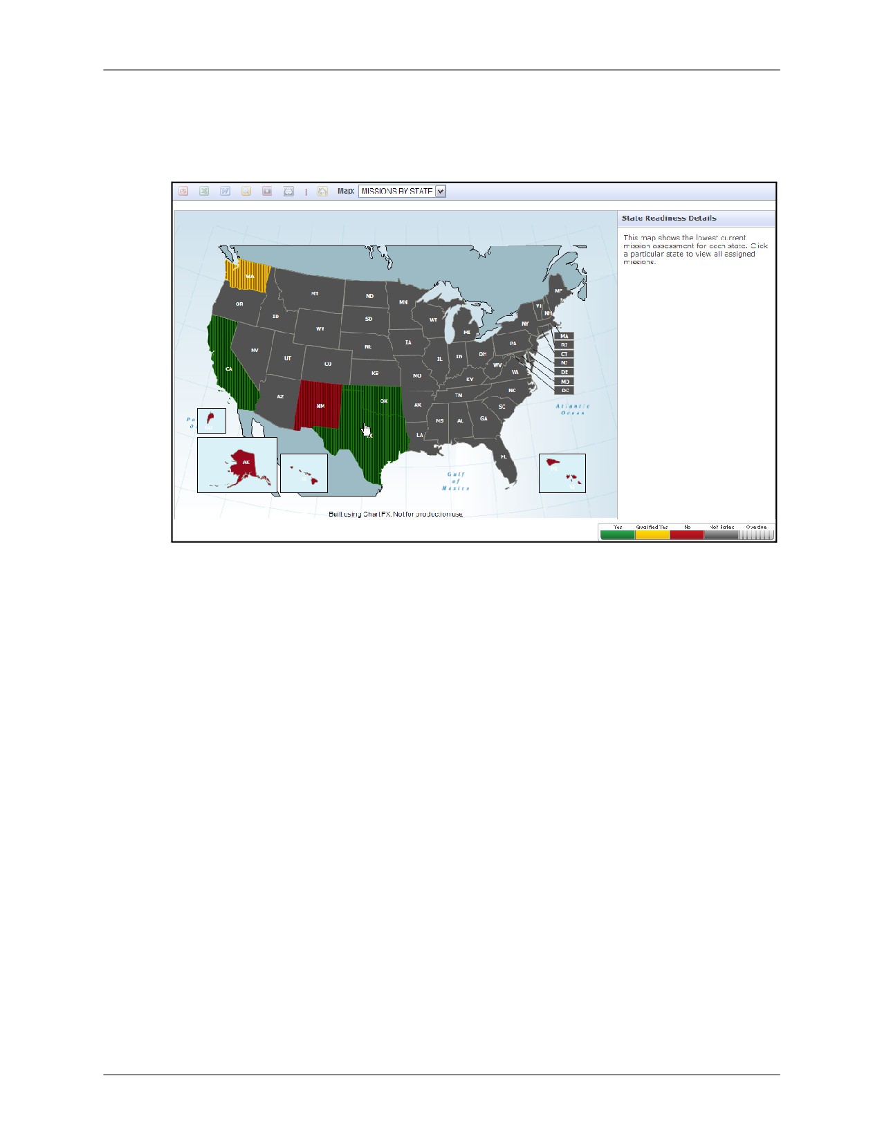
Figure 13-1: State Readiness Dashboard
Every state reporting readiness via ESORTS will have a corresponding readiness color
representing the lowest readiness assessment value according to the map you select. The
available colors are green (Y), yellow (Q), red (N), and grey (Not Assessed). States showing
gray vertical stripes signify an overdue assessment, meaning that the last reporting date was
more than 30 days ago.
13-2
DRRS Software User Manual (SUM) 4.5.12

Chapter 13: State Readiness Dashboard
Dashboard Maps
13.2
Dashboard Maps
The State Readiness Dashboard has three unique maps which are selectable using the Map
dropdown menu in the CT Toolbar. These views are used to show:
• Missions by State: Lowest current mission assessment value in each state. This is the
default view.
• States by Mission: Lowest current assessment value for a selected mission across all
states. Only states that have been assigned that particular mission will display a value.
• Essential 10: National Guard “Essential 10” capabilities for Domestic Operations for
each state.
13.2.1
Missions by State
The map of Missions by State shows the lowest current mission assessment value of every
state. By doing so, this view provides a general readiness mapping for the entire country.
To view mission assessments by state, open the Readiness Dashboard and select Missions by
State from the Map dropdown on the CT Toolbar.
Figure 13-2: Missions by State
Clicking on a state will display the missions assigned to that state and their readiness values in
the panel on the far right of the readiness dashboard.
DRRS Software User Manual (SUM) 4.5.12
13-3

Dashboard Maps
Chapter 13: State Readiness Dashboard
13.2.2
States by Mission
The map of States by Mission allows you to select a mission and view the lowest current
assessment value for that mission in each state it is assigned to. This view provides an overall
readiness mapping for a particular mission across the country.
To view assessments by mission, open the Readiness Dashboard and select States by Mission
from the Map dropdown on the CT Toolbar. Next, select a mission from the Mission dropdown.
Figure 13-3: States by Mission
Clicking on a state will display the missions assigned to that state and their readiness values in
the panel on the far right of the readiness dashboard.
13.2.3
States by Essential 10
The States by Essential 10 map is designed to provide quick access to the subjective
evaluations of the National Guard “Essential 10” capability areas submitted by each state. The
Essential 10 areas are:
• Aviation / Airlift
• Chemical, Biological, Radiological, Nuclear, and high-yield Explosives (CBRNE)
response
• Command and Control (C2)
• Communications
• Engineering
• Logistics
• Maintenance
• Medical
• Security
• Transportation
13-4
DRRS Software User Manual (SUM) 4.5.12

Chapter 13: State Readiness Dashboard
Dashboard Maps
Evaluations for the Essential 10 are subjective in nature, evaluated by each state, and are not
currently applied against a standard metric; however, a range for each capability is proposed to
provide enhanced consistency when evaluating capabilities for the National Guard on a
nationwide basis. The rating scale for these evaluations is as follows:
• Green: Unit has a high degree of capability to perform the particular Joint Core
Capability mission.
• Yellow: Unit has a limited capability to perform the particular Joint Core Capability
mission.
• Red: Unit does not have the capability to perform the particular Joint Core Capability
mission.
Capability levels for each state are evaluated on two levels, both of which are visible through the
State Readiness Dashboard:
• Level One: Domestic Operations Support Capabilities provided by the states evaluated
over the course of the last 10 years (fires, floods, tornadoes, hurricanes, power
outages, winter storms, etc.).
• Level Two: Response capabilities as evaluated against those scenarios states have
not traditionally encountered. These are currently based on the National Planning
Scenarios as published by the Homeland Security Council.
For more detailed information on the Essential 10 capabilities and their use, please refer to the
Joint Capabilities Database (JCD) documentation.
To view the Essential 10 evaluations by state, open the Readiness Dashboard and select
Essential 10 from the Maps dropdown in the CT Toolbar. Next, select one of the two levels from
the Type dropdown.
Figure 13-4: States by Essential 10
Clicking on a state will display the missions assigned to that state as well as each of the
Essential 10 categories and their readiness values in the panel on the far right of the readiness
dashboard.
DRRS Software User Manual (SUM) 4.5.12
13-5

States Drill-Down
Chapter 13: State Readiness Dashboard
13.3
States Drill-Down
Using State Readiness Dashboard, it is possible to access more detailed information for a
particular state as well. From any of the readiness maps described in the previous sections,
click on a state to bring up the overview of that state’s assigned missions and their
assessments. This information will display in the upper-right corner of the Readiness
Dashboard.
Figure 13-5: State Details
Clicking the state UIC at the top of the details panel provides access to METL details, overall
assessment, and Essential 10 assessments for that particular state.
13.3.1
METL Details
The MEL tab contains detailed information about the selected state’s Mission Essential Task
List (METL). For more information about the METL, refer to Chapter 6: About ESORTS.
Figure 13-6: State METL Details
13-6
DRRS Software User Manual (SUM) 4.5.12

Chapter 13: State Readiness Dashboard
States Drill-Down
13.3.2
Overall Assessment
The overall assessment tab provides the current and projected assessment value for each
mission assigned to the selected state. It also provides access to the Commander’s override
comments and rating. For more information, refer to Chapter 6: About ESORTS.
Figure 13-7: State Overall Assessment
13.3.3
Essential 10
The Essential 10 tab shows the assessment values for each of the Essential 10 categories at
Level One and Level Two. Each category can also support Sub-State assessments which are
used to represent any entity whose capabilities impact the overall assessment of that capability
category. These can be accessed by expanding any of the essential 10 category listings which
is done by clicking the grey plus sign next to that category’s name.
Figure 13-8: State Essential 10 Tab
In order to add/edit state or sub-state assessments, you must have:
• The selected state set as either your Primary or Secondary Unit of Assignment.
• Unit Admin or Unit Commander privileges for the selected state or the Joint Readiness
Editor role.
DRRS Software User Manual (SUM) 4.5.12
13-7

States Drill-Down
Chapter 13: State Readiness Dashboard
13.3.3.1
Adding State Assessments
State Assessments are used to show the overall capability of a state’s capabilities within a
particular Essential 10 category. To add a new State Assessment:
1. Click the Edit button (pencil icon) next to the capability category you wish to assess.
2. Select an assessment value for Level One.
3. Enter any comments pertinent to the assessment value being added.
Note: You may choose to enter only comments and not an the assessment rating.
4. Repeat steps 2 and 3 for Level Two assessment.
5. Click Submit.
13-8
DRRS Software User Manual (SUM) 4.5.12

Chapter 13: State Readiness Dashboard
States Drill-Down
13.3.3.2
Adding Sub-State Assessments
Sub-State assessments are used to represent the capabilities of any entity that reports to a
state within the context of a particular Essential 10 category. To add a new Sub-State
assessment:
1. Click Add Sub-State Assessments.
Figure 13-9: Adding Sub-State Assessments
2. Select the capability category for which you are adding an assessment.
3. Enter a name for the assessment entity being entered.
4. Enter the code associated with the assessment entity being entered.
5. Select an assessment value for this entity.
6. Move all applicable remarks into the Current Remarks field from the Available Remarks field
using the arrow buttons between these fields.
7. Click Submit.
DRRS Software User Manual (SUM) 4.5.12
13-9
State Capability Trees
Chapter 13: State Readiness Dashboard
13.4
State Capability Trees
The State Readiness dashboard links directly to the Capability Trees Module which is designed
to help mission planners more easily create the supporting structure necessary for managing
mission readiness. By allowing them to create a graphical representation of the required
organizational structure, choosing their entire list of resources, and then providing the readiness
assessment value for each unit associated with the mission, it drastically simplifies the process
of constructing a viable mission structure.
Structures only apply to the state UIC under which they are created, regardless if the same
mission is associated with several states.
13.4.1
Accessing Capability Trees for a State
To view the Capability Tree(s) for a particular state:
1. Access the State Readiness Dashboard and, from any of the map views, click on a state.
2. From the details panel that appears in the upper-right corner, click on any of the mission
names associated with the selected state. Doing so will take you directly to the Capability
Tree for that mission in the selected state. For more information on Capability Trees, refer to
Chapter 15: About Capability Trees.
13-10
DRRS Software User Manual (SUM) 4.5.12
PART VI:
Utilities
This Page Intentionally Left Blank.
Chapter 14: Quick Search
Chapter 14: Quick Search
The DRRS Quick Search tool provides the functionality to search through the system for specific
Units or Personnel and view their associated readiness data. This feature provides a
streamlined toolset designed to provide a quick and easy searching mechanism.
This chapter consists of the following topics:
• Performing a Unit Search
• Performing a Personnel Search
• Performing an Equipment Search
• Performing an Ordnance Search
• Creating a Group from Search Results
• Exporting Search Results
DRRS Software User Manual (SUM) 4.5.12
14-1

Performing a Unit Search
Chapter 14: Quick Search
14.1
Performing a Unit Search
The Unit Quick Search provides three methods for finding units: by Task, by Mission, or by
Name/UIC.
14.1.1
By Task
To find the units associated with a specific task:
1. Select Utilities | Quick Search | Unit Search from the Main Menu.
Figure 14-1: Unit Search by Task
2. Select Tasks from the Search For dropdown menu.
3. Select an option from the Search By dropdown menu. The choices are:
• Task Number
• Task Title
• Task Description
4. Select a Service and/or Component to limit your search to.
5. Enter a phrase to search for in the Search Phrase field. Based on your Search By selection,
this could be all or part of a task number, title, or description.
Unless you are entering the exact title or description, click the Add Wildcards checkbox to
increase the number of search results returned.
6. Click Search.
Figure 14-2: Task Search Results
14-2
DRRS Software User Manual (SUM) 4.5.12

Chapter 14: Quick Search
Performing a Unit Search
The tasks matching your search criteria are displayed along with the number of units
associated with each task. Clicking the hyperlinked number of any task will show the details
of that task in a separate window next to the task search results.
7. Select the tasks whose supporting units you wish to see by clicking the corresponding
checkbox for each task.
8. Select whether to search for units performing All or Any of the selected missions using the
dropdown menu at the bottom of the task search results.
9. Click Search for Units.
Figure 14-3: Units by Task
The units supporting the selected task(s) are displayed in a separate search results window.
To view the details of a particular unit, click that unit’s hyperlinked UIC and a window
containing detailed information for that unit is displayed next to the unit results.
You may also create a new group based on the search results. For more information, see
Section 14.5: Creating a Group from Search Results.
14.1.2
By Mission
To find the units associated with a specific mission:
1. Select Utilities | Quick Search | Unit Search from the Main Menu.
Figure 14-4: Unit Search by Mission
DRRS Software User Manual (SUM) 4.5.12
14-3

Performing a Unit Search
Chapter 14: Quick Search
2. Select Missions from the Search For dropdown menu.
3. Select an option from the Search By dropdown menu: The choices are:
• Mission Name
• Mission Number
4. Select a Service and/or Component to limit your search to.
5. Enter a phrase to search for in the Search Phrase field. Based on your Search By selection,
this could be all or part of a mission name or number.
Unless you are entering the exact mission name or number, click the Add Wildcards
checkbox to increase the number of search results returned.
6. Click Search.
Figure 14-5: Mission Search Results
The missions matching your search criteria are displayed along with the number of units
associated with each mission. Clicking the hyperlinked number of any mission will show the
details of that mission in a separate window next to the mission search results.
7. Select the missions whose supporting units you wish to see by clicking the corresponding
checkbox for each mission.
8. Select whether to search for units performing All or Any of the selected missions using the
dropdown menu at the bottom of the mission search results.
9. Click Search for Units.
14-4
DRRS Software User Manual (SUM) 4.5.12

Chapter 14: Quick Search
Performing a Unit Search
Figure 14-6: Units by Mission
The units supporting the selected mission(s) are displayed in a separate search results
window. To view the details of a particular unit, click that unit’s hyperlinked UIC and a
window containing detailed information for that unit is displayed next to the unit results.
You may also create a new group based on the search results. For more information, see
Section 14.5: Creating a Group from Search Results.
DRRS Software User Manual (SUM) 4.5.12
14-5

Performing a Unit Search
Chapter 14: Quick Search
14.1.3
By Name/UIC
To find a specific unit:
1. Select Utilities | Quick Search | Unit Search from the Main Menu.
Figure 14-7: Unit Search by Name
2. Select Units from the Search For dropdown menu.
3. Select an option from the Search By field. The options are:
• UIC / Unit name
• SRC
• TPSN
• UTC
• Current Location Code
• Current Location Name
4. Select a Service and/or Component to limit your search to.
5. In the Search Phrase field, enter all or part of the phrase to search for.
Unless you are entering the exact name or number, click the Add Wildcards checkbox to
increase the number of search results returned.
6. Click Search.
Figure 14-8: Unit Search Results
The units matching your search criteria are displayed. To view the details of a particular
unit, click that unit’s hyperlinked UIC and a window containing detailed information for that
unit is displayed next to the unit results. You may also create a new group based on the
search results. For more information, see Section 14.5: Creating a Group from Search
Results.
14-6
DRRS Software User Manual (SUM) 4.5.12

Chapter 14: Quick Search
Performing a Personnel Search
14.2
Performing a Personnel Search
There are several methods for searching for personnel. Each is described below.
14.2.1
By Occupational Specialty
To find personnel by occupational specialty:
1. Select Utilities | Quick Search | Personnel Search from the Main Menu.
Figure 14-9: Personnel Search by Occupation
2. Select Occupational Specialties from the Search By dropdown menu.
3. Additionally, you may filter your search to only enlisted personnel, officers, or warrant
officers.
4. Select a Service and/or Component to limit your search to.
5. In the Search Phrase field, enter all or part of the occupational specialty code or description
to search for.
Unless you are entering the exact code or description, click the Add Wildcards checkbox to
increase the number of search results returned.
Tip: If you are searching for Occupational Specialty Codes, you can search for multiple codes by entering
the codes separated by a comma with no spaces in between. Checking the Add Wildcards box will
automatically add wildcards around each of the search phrases. For example, to search for codes x, y,
and z, enter the search phrase “x,y,z”. Click Add Wildcards and this becomes “ *x*, *y*, *z* ”.
6. Click Search.
Figure 14-10: Occupation Search Results
DRRS Software User Manual (SUM) 4.5.12
14-7
Performing a Personnel Search
Chapter 14: Quick Search
The occupational specialties matching your search criteria are displayed. Clicking the
hyperlinked code of an occupational specialty will display the details of that occupation,
including the related DoD occupation codes, in a separate window next to the search
results.
You may change the display of search results by selecting one of the three radio buttons at
the top:
•
Simple: Displays the results matching your specific search criteria.
•
Expanded by DodOcc: Displays the results matching your search criteria as well
as any other occupations matching to similar DoD occupation codes.
•
Expanded by Description: Displays the results matching your search as well as
any other occupations having a similar description.
7. Select the occupations whose assigned personnel you wish to find by selecting the
corresponding checkbox for each occupation.
8. Select whether to search for personnel with Any or All of the selected occupations.
9. Click Search for People.
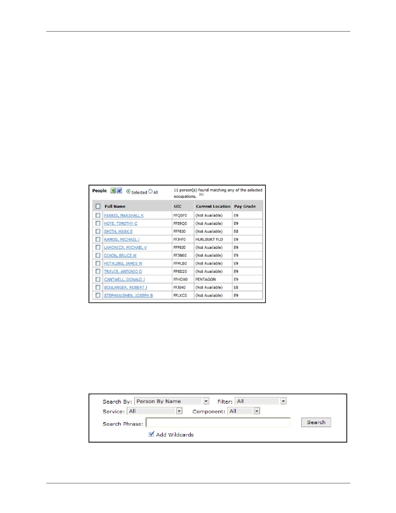
Figure 14-11: Personnel by Occupation
The personnel supporting the selected occupation(s) are displayed in a separate search
results window. To view the details of a particular person, click that person’s hyperlinked
name and a window containing detailed information for that person is displayed next to the
personnel results.
14.2.2
By Name
To find personnel by name:
1. Select Utilities | Quick Search | Personnel Search from the Main Menu.
Figure 14-12: Personnel Search by Name
2. Select Person by Name from the Search By dropdown menu.
14-8
DRRS Software User Manual (SUM) 4.5.12

Chapter 14: Quick Search
Performing a Personnel Search
3. Additionally, you may filter your search to only enlisted personnel, officers, or warrant
officers.
4. Select a Service and/or Component to limit your search to.
5. In the Search Phrase field, enter all or part of the name of the person you are searching for.
Unless you are entering the exact name, click the Add Wildcards checkbox to increase the
number of search results returned.
6. Click Search.
Figure 14-13: Personnel Search Results
The personnel matching your search criteria are displayed. To view the details of a
particular person, click that person’s hyperlinked name and a window containing detailed
information for that person is displayed next to the personnel results.
14.2.3
By Unit
To find personnel associated with a specific unit:
1. Select Utilities | Quick Search | Personnel Search from the Main Menu.
Figure 14-14: Personnel Search by Unit
2. Select Units in the Search By dropdown menu.
3. Additionally, you may filter your search to only enlisted personnel, officers, or warrant
officers.
4. Select a Service and/or Component to limit your search to.
5. In the Search Phrase field, enter all or part of the unit ANAME or UIC.
Unless you are entering the exact name or number, click the Add Wildcards checkbox to
increase the number of search results returned.
6. Click Search.
DRRS Software User Manual (SUM) 4.5.12
14-9

Performing a Personnel Search
Chapter 14: Quick Search
Figure 14-15: Personnel by Unit Search Results
The units matching your search criteria are displayed. Clicking the hyperlinked code of a
unit will display the details of that unit in a separate window next to the search results.
7. Select the units whose assigned personnel you wish to find by selecting the corresponding
checkbox for each unit.
8. Click Search for People.
Figure 14-16: Personnel by Name
The personnel supporting the selected unit(s) are displayed in a separate search results
window. To view the details of a particular person, click that person’s hyperlinked name and
a window containing detailed information for that person is displayed next to the personnel
results.
14-10
DRRS Software User Manual (SUM) 4.5.12

Chapter 14: Quick Search
Performing a Personnel Search
14.2.4
By Language
To find personnel proficient in a particular language:
1. Select Utilities | Quick Search | Personnel Search from the Main Menu.
Figure 14-17: Personnel Search by Language
2. Select Language in the Search By dropdown menu.
3. Additionally, you may filter your search to only enlisted personnel, officers, or warrant
officers.
4. Select a Service and/or Component to limit your search to.
5. In the Search Phrase field, enter all or part of the desired language.
Unless you are using the exact name or code, click the Add Wildcards checkbox to
increase the number of search results returned.
6. Click Search.
Figure 14-18: Personnel by Language
The personnel proficient in the selected languages are displayed. To view the details of a
particular person, click that person’s hyperlinked name and a window containing detailed
information for that person is displayed next to the personnel results.
DRRS Software User Manual (SUM) 4.5.12
14-11
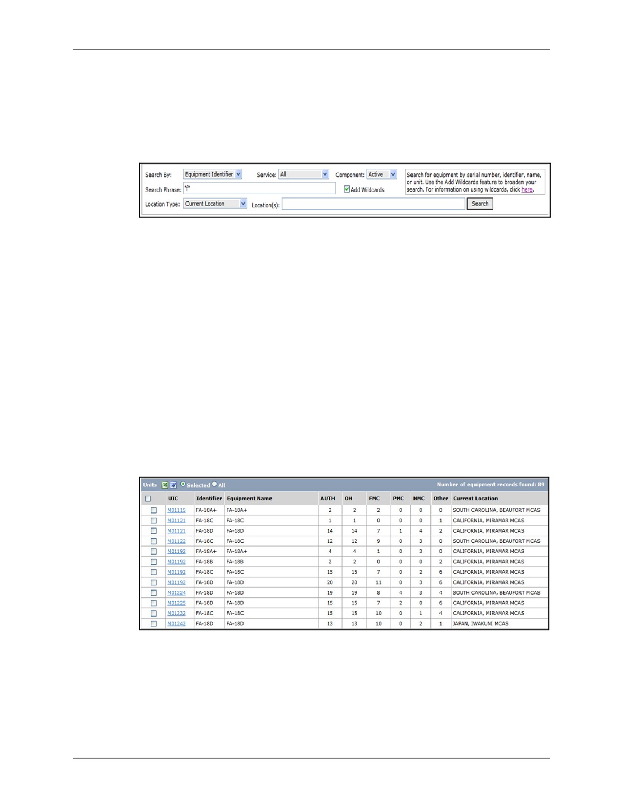
Performing an Equipment Search
Chapter 14: Quick Search
14.3
Performing an Equipment Search
The equipment search function allows you to search for specific equipment and then locate
units with that equipment.
To perform an equipment search:
1. Select Utilities | Quick Search | Equipment Search from the Main Menu.
2. Select an option from the Search By dropdown menu. The options are:
• Serial Number
• Equipment Identifier
• Equipment Name
• Unit
3. Select a Service and/or Component to limit your search to.
4. In the Search Phrase field, enter all or part of the phrase to search for.
Unless you are entering the exact name or number, click the Add Wildcards checkbox to
increase the number of search results returned.
5. You can also select a location type to narrow your search by. The options are:
• Current Location
• Home Location
• Both
6. Enter the corresponding location code in the Location(s) field.
7. Click Search.
Figure 14-19: Equipment Search Results
a. If you are not searching by Serial number, your search results will include all units
associated with the equipment matching your search criteria. You can now find
equipment assigned to one or more of these units by selecting the checkbox next to the
corresponding unit(s) and clicking Search for Equipment.
b. If you are searching by Serial number, your search results will contain the equipment
matching your search criteria.
14-12
DRRS Software User Manual (SUM) 4.5.12

Chapter 14: Quick Search
Performing an Equipment Search
Figure 14-20: Units by Equipment
DRRS Software User Manual (SUM) 4.5.12
14-13
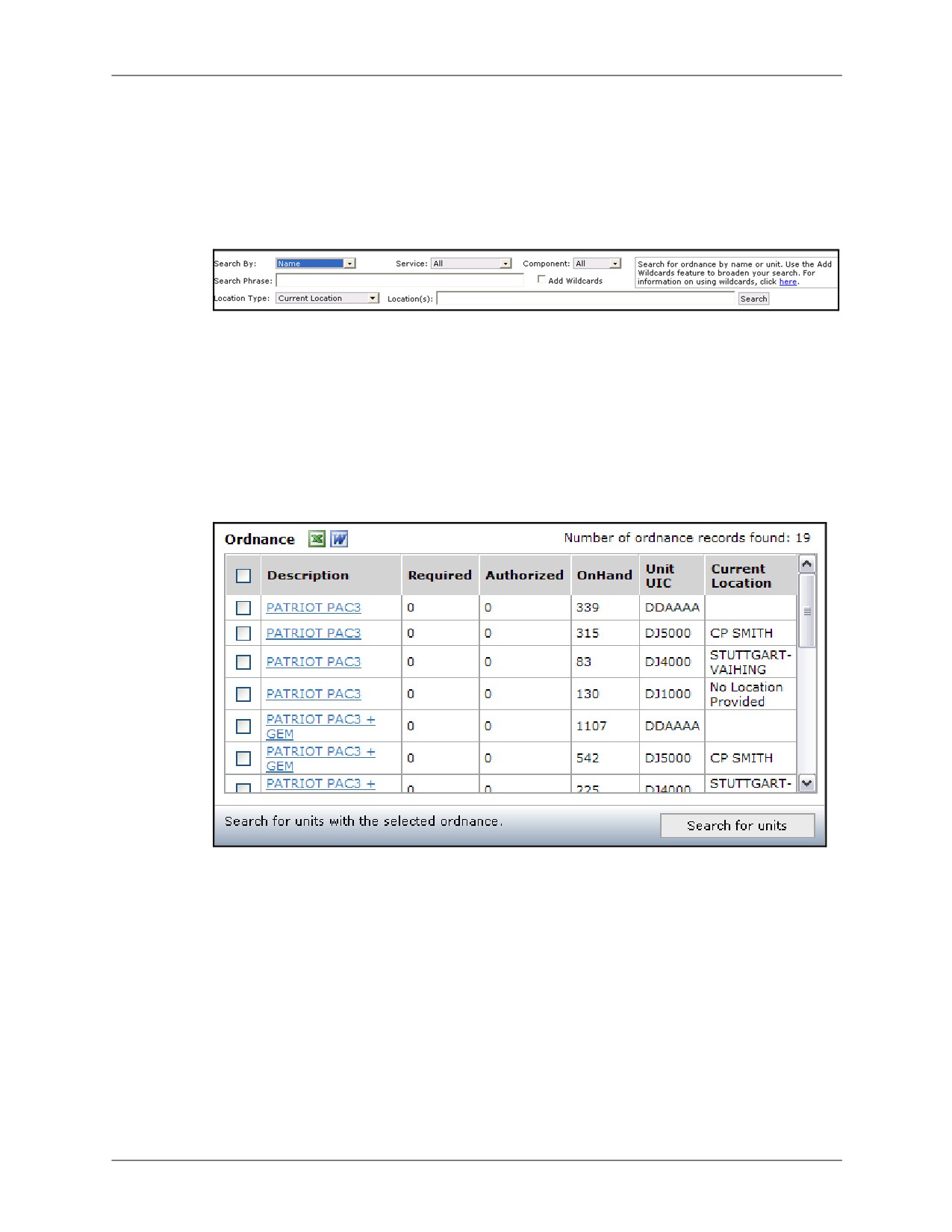
Performing an Ordnance Search
Chapter 14: Quick Search
14.4
Performing an Ordnance Search
The ordnance search function allows you to search for specific ordnance and then locate units
or locations with that equipment.
To perform an ordnance search:
1. Select Utilities | Quick Search | Ordnance Search from the Main Menu.
2. Select an option from the Search By dropdown menu. The options are:
• Name
• UIC
3. Select a Service and/or Component to limit your search to.
4. In the Search Phrase field, enter all or part of the phrase to search for.
Unless you are entering the exact name or number, click the Add Wildcards checkbox to
increase the number of search results returned.
5. Click Search.
Figure 14-21: Ordnance Search Results
The ordnance matching your search criteria are displayed. To view the details of a particular
item, click the corresponding hyperlinked Description and a window containing detailed
information for that item is displayed next to the search results.
14-14
DRRS Software User Manual (SUM) 4.5.12

Chapter 14: Quick Search
Performing an Ordnance Search
6. Select the ordnance whose supporting units you wish to see by selecting the corresponding
checkboxes and clicking the Search for Units button.
Figure 14-22: Units by Ordnance
The units supporting the selected ordnance are displayed in a separate search results
window. To view the details of a particular unit, click that unit’s hyperlinked UIC and a
window containing detailed information for that unit is displayed. You may also create a new
group based on the search results. For more information, see Section 14.5: Creating a
Group from Search Results.
14.4.1
Using Wildcards
In order to provide a wider range of results, all searches will use implicit wildcards, unless
otherwise stated. This means that wildcard characters (*) will be added before and after your
search phrase, returning any result containing the phrase you entered. For example, a search
for "ge" is the same as "*ge*" and will return "Gettysburg", "Agency", and "Anchorage". For a
more precise search, enter as much information as possible or manually use wildcards.
There are three ways to add wildcards, before a search phrase, after a search phrase, or inside
a search phrase.
1. Before (*xyz): Returns results with any character(s) preceding the search phrase. Results
would include wxyz, vwxyz, uxyz, etc.
2. After (abc*): Returns results with any character(s) following the search phrase. Results
would include abcd, abcde, abce, etc.
3. Inside (a*c): Returns results with any character in the specified wildcard spot. Results would
include abc, acc, adc, etc.
DRRS Software User Manual (SUM) 4.5.12
14-15

Creating a Group from Search Results
Chapter 14: Quick Search
14.5
Creating a Group from Search Results
To create a new group based on your search results, select the checkbox next to the desired
units and click the Create Group button. In the Create Group dialog, enter a unique name for
your new group, select which type of group you are creating, and click Submit. When created
successfully, this group will be available for viewing in the Group Builder.
Figure 14-23: Create Groups from Search Results
14-16
DRRS Software User Manual (SUM) 4.5.12
Chapter 14: Quick Search
Exporting Search Results
14.6
Exporting Search Results
To export the results from a search, select all the items to be exported by selecting their
corresponding checkboxes and then clicking the Excel or Word export button.
DRRS Software User Manual (SUM) 4.5.12
14-17
Exporting Search Results
Chapter 14: Quick Search
14-18
DRRS Software User Manual (SUM) 4.5.12
Chapter 15: About Capability Trees
This chapter provides an introduction to Capability Trees, the types of trees available, and their
purpose in mission planning. This chapter will also introduce each of the tools contained in the
Capability Trees Module.
DRRS Software User Manual (SUM) 4.5.12
15-1
What are Capability Trees?
Chapter 15: About Capability Trees
15.1
What are Capability Trees?
Capability Trees are user-created visual representations of structures. These structures may be
used to represent organizational hierarchies, mission structures, or any other relational
configuration required.
Users may access the Capability Trees module and its tools by selecting Utilities | Capability
Trees from the Main menu. All users have access to this module.
Note: Although any user may view existing trees for any unit (using the Unit Selector), a user
may only create, edit, and delete trees for their Primary and Secondary Unit of Assignment.
Similarly, users can only delete trees that they themselves have created.
15.1.1
Types of Trees
There are three types of Capability Trees:
• Organizational Structure: Used to represent an org structure in the DRRS system.
This can be a particular organization and its subordinate orgs.
• Mission Structure: Allows creation of a tree in representing an ESORTS mission
assigned to a particular organization, including subordinate tasks.
• Custom Structure: Freeform tree allowing manual creation of any tree configuration.
This type of structure provides the same functionality as the others, the key difference
being that this type is all created manually rather than using existing structures.
15-2
DRRS Software User Manual (SUM) 4.5.12
Chapter 15: About Capability Trees
Getting Started
15.2
Getting Started
The following sections provide a brief description of the tools used within the CT module.
15.2.1
CT Toolbar
The Capability Trees module contains a common toolbar throughout. This toolbar, called the
Capability Trees Toolbar, or CT Toolbar, provides access to key tools used in the creation and
management of Capability Trees.
Figure 15-1: Capability Trees Toolbar (CT Toolbar)
The items provided by the CT Toolbar include:
• PowerPoint Export: Not currently enabled.
• Excel Export: Not currently enabled.
• Word Export: Not currently enabled.
• Search: Not currently enabled.
• Snapshot: Not currently enabled.
• Print: Not currently enabled.
• Control Center: Navigates directly back to the Control Center, the hub for Capability
Tree management.
• Create New Tree: Starts the New Tree Wizard which provides a step-by-step method
for creating new Capability Trees.
• Edit Tree: Opens the currently viewed tree in the Tree Wizard, allowing changes to be
made to that tree’s setup.
• Tree View Filter: Provides a selection of tree views including:
•
Setup: Manage the tree structure and related aspects.
•
Assign Resources: Assign units, equipment, or individuals in support of your tree.
•
Assessment: View the finished product as well as drill into more detail on the
resources assigned to your tree.
15.2.2
Control Center
The Capability Tree Control Center is the starting point for creating and managing Capability
Trees. To access the Control Center, select Utilities | Capability Trees from the Main menu.
The Control Center displays the Capability Trees for the unit you have selected in the Unit
Selector. For more information on the Unit Selector, refer to Chapter 5: Working with Groups
and Units.
DRRS Software User Manual (SUM) 4.5.12
15-3

Getting Started
Chapter 15: About Capability Trees
Figure 15-2: Capability Trees Control Center
The Control Center contains a listing of the existing trees and their details, including:
• Name: Hyperlinked name of each tree. Clicking this hyperlink name opens the tree on
the Setup page so that you can begin adding resources and editing the general display.
• Type: Indicates the type of tree (Organization, Mission, or Custom). You can use the
Filter by menu in the upper-right corner to control the types of trees to display.
• Mission: You have the ability to associate every tree with a particular mission from the
Mission Assessment module. This column indicates the associated mission.
• Created By: User name of the user who initially created the tree.
• Created On: Date and time the tree was created.
• Last Modified By: User name of the user who last modified the tree.
• Modified On: Date and time the tree was last modified.
• Status: Indicates if tree is publicly viewable (“Shared”) or private (only the tree’s creator
can view “Private” trees*).
The Control Center also provides icons allowing the editing, deleting, creating, and copying of
trees. Each of these functions is described in further detail in the following chapters.
*Enterprise Admins can view any tree in the system, including those set as private.
15.2.2.1
Viewing Trees for Other Units in DRRS
The Control Center allows you to view the trees for your Primary and Secondary Unit of
Assignment (default) or to view trees for any unit in DRRS via the Unit Selector. To view trees
for a particular unit, access the Unit Selector and choose the desired unit. For more information,
see Chapter 5.1: Unit Selector.
Note: You may only select a single unit from the Unit Selector. It does not support viewing groups.
15-4
DRRS Software User Manual (SUM) 4.5.12

Chapter 15: About Capability Trees
Getting Started
15.2.2.2
Discussion Board
Just below the Control Center is the Discussion Board. All users can view, post, and reply to
messages on this board. To do so:
1. Access the CT Control Center.
2. To post a new message, click the Add New Message button located in the upper-right
corner of the discussion board. To respond to an existing message, click the Post Reply
button (plus sign) next to the corresponding message.
Figure 15-3: CT Discussion Board
3. In the Add New Message or Post Reply popup that appears, enter a title for your message
and the message itself.
Figure 15-4: Add New Message
4. If desired, attach a file to include with your message using the Browse button (10mb max).
5. Click Post Message.
Unit Commanders and Unit Administrators have permissions to delete old messages for their
Primary and Secondary Units of Assignment. Enterprise Administrators can delete messages
for any unit.
DRRS Software User Manual (SUM) 4.5.12
15-5

Getting Started
Chapter 15: About Capability Trees
15.2.3
Tree Wizard
The Tree Wizard walks you through a four step process for creating new trees. By following the
on-screen instructions, you will be prompted to select a tree type, an organization or mission,
and the specific data to display. Detailed instructions for creating a new Capability Tree are
provided in Chapter 2: Creating Trees.
Figure 15-5: Capability Trees Wizard
To access the Tree Wizard, you can select the Create New Tree icon on the CT Toolbar
or
you can select the Create New Tree button in the lower-right corner of the Control Center.
15.2.4
Tree Views
Once a tree has been created, it can be opened from the Control Center for viewing using the
Tree Views tool which features three different view for a tree structure, each designed to provide
a unique look at one aspect of the tree. These views are:
• Setup: Visually displays the customizable tree hierarchy as well as allowing you the
ability to modify the structure by adding, editing details for, or removing individual tree
nodes.
• Assign Resources: Detailed view of the units, personnel, or equipment assigned to
support a tree structure. This view allows you the ability to add or remove resources to
each node in the tree as needed.
• Assessment: Displays a read-only tree hierarchy view containing the assessment
values for resources assigned to that tree as well as linking to the resources assigned
to each node. This view is optimal for using in live demonstrations or displaying in
PowerPoint slide shows.
Each of these views is discussed in detail in the chapters that follow.
15-6
DRRS Software User Manual (SUM) 4.5.12