Military reference books and manuals (2009-2023, Volume 3) - page 22
Chapter 16: Creating Trees
Chapter 16: Creating Trees
This chapter will focus on the creation of new Capability Trees in two different ways:
• Using the Tree Wizard
• Via the Copy Tree capability
DRRS Software User Manual (SUM) 4.5.12
16-1

Using the Tree Wizard
Chapter 16: Creating Trees
16.1
Using the Tree Wizard
The process for creating a new tree is made simple through the use of a step-by-step
walkthrough mechanism called the Tree Wizard. This wizard will prompt you for specific
information and provide you with options for the creation of your new tree.
To begin creating a tree:
1. Select Utilities | Capability Trees from the Main menu.
2. Click the Create New Tree button on the CT Toolbar to open the Tree Wizard. The
introduction screen displays. This provides a brief overview of the tree creation process.
Figure 16-1: Tree Wizard Introduction Screen
3. At the introduction screen, click Next.
16-2
DRRS Software User Manual (SUM) 4.5.12
Chapter 16: Creating Trees
Using the Tree Wizard
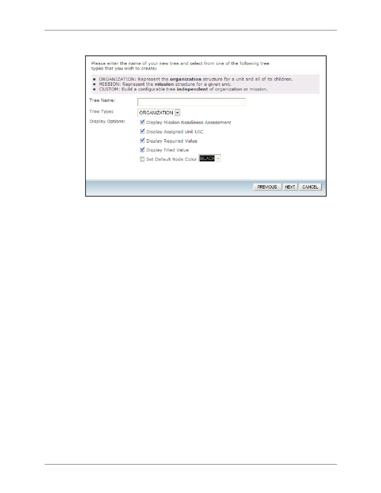
The Basic Information screen displays. Setting up a new tree begins here.
Figure 16-2: Tree Wizard Basic Information Screen
4.
Enter a unique name for the tree you are creating.
5.
Select the type of tree to create. There are three types of Capability Trees:
• Organization: Used to represent an org structure in the DRRS system. This can be a
particular organization and, optionally, its subordinate orgs.
• Mission: Allows creation of a tree in representing an ESORTS mission assigned to a
particular organization, including subordinate tasks (optional).
• Custom Structure: Freeform tree allowing manual creation of any tree configuration.
This type of structure provides the same functionality as the others, the key difference
being that this type is all created manually rather than using existing structures. This is
the choice for equipment or personnel trees as you do not need to display data
involving orgs or mission assessments.
6.
Choose from a list of display options. These options determine what data will be made
visible on each node when viewing the tree on the Assessment page. Do not worry if you
are unsure of what to choose as you can always come back later and quickly change these
options.
• Display Assigned UIC: Shows the unit identification code for the unit that you can
choose to assign as the role provider to a tree node.
• Display Filled Value: Lists the total number of resources you have added to a tree
node on the Assign Resources page.
• Display Mission Readiness Assessment: A Y, Q, or N icon will display for each node
that has an approved readiness assessment for the mission you can optionally select in
the next step of the wizard. If there is no mission, an NR will display. In addition, you
have the option of manually assigning a readiness value to a node.
• Display Required Value: Set a number for each node to have as a target for
resources. This is useful for comparison against the actual numbers (Filled).
• Set Default Node Color: Allows you to choose the color of your liking for all tree nodes.
Please note that you can only choose this option one time upon first creating tree,
however you can always change each node color later on the Setup page.
DRRS Software User Manual (SUM) 4.5.12
16-3
Using the Tree Wizard
Chapter 16: Creating Trees
7. Click Next. The next step is to configure the tree you selected. Depending on the tree type
selected in the Basic Information screen, this screen will contain different selections
described in the following subsections. Please read the section for the tree type that you
selected in Step 5 on the previous page.
16.1.1
Mission Tree Type
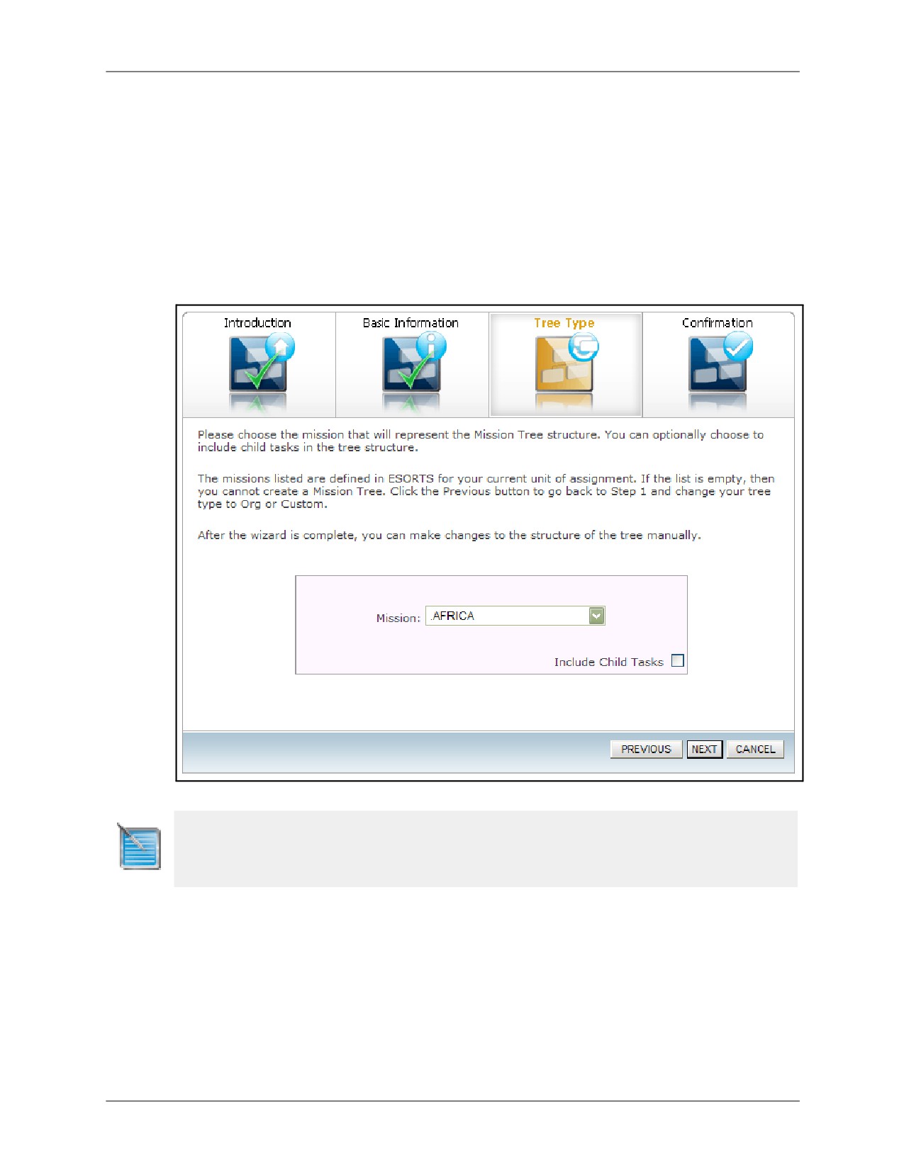
If you selected the Mission tree type, the Tree Type page will prompt you to select one of the
ESORTS missions associated with your Unit of Assignment using the Mission dropdown menu.
Optionally, you may choose to include the subordinate tasks for the selected mission by
selecting the Include Child Tasks checkbox.
Figure 16-3: Mission Tree Type Details
Note: Missions will only show up in the dropdown menu if you have a mission created in ESORTS Build
METL. Mission Assessments will only display for approved missions or tasks in ESORTS Mission
Assessment.
16-4
DRRS Software User Manual (SUM) 4.5.12

Chapter 16: Creating Trees
Using the Tree Wizard
16.1.2
Organization Tree Type
When the Organization tree type is selected, the Tree Type page will prompt you to search for
the organization this tree structure will represent.
Figure 16-4: Organization Tree Type Details
To configure the Organization tree type:
1. Enter all or part of the unit UIC/AName in the UIC/AName field and click Search. Select the
desired organization from the search results.
2. Choose whether to include subordinate organizations using the Include Child
Organizations checkbox. This is advised to see the entire org structure. If subordinate
organizations are to be included, select the relationship type that will be providing those
organizations (OPCON, ADCON, or COCOM).
3. Choose a mission to associate with the nodes of the selected organization.
Note 1: Missions will only show up in the dropdown menu if you have a mission created in ESORTS Build
METL. Mission Assessments will only display for approved missions or tasks.
Note 2: Org Trees that show huge organizations (more than 250 children) will perform slower than normal
trees. This is due to the large amount of data that needs to be obtained from the DRRS Org Database.
DRRS Software User Manual (SUM) 4.5.12
16-5

Using the Tree Wizard
Chapter 16: Creating Trees
16.1.3
Custom Tree Type
When the Custom tree type is selected, the Tree Type page will prompt you for the name to be
applied to the root node in the tree structure as well as an associated mission. You can always
change the root name once you have created the tree.
Figure 16-5: Custom Tree Type Details
16.1.4
Confirmation
1. Once you are done with one of the above tree types, click the Next button.
2. The final step of the Tree Wizard is to confirm your selections from the previous steps. A
summarized confirmation page will be displayed.
a. If any of the information/settings are not correct, use the Previous button to return to
the desired screen and make the necessary changes.
b. If all the information/settings are correct, click Save Tree to finalize the creation of the
tree and exit the Tree Wizard. You will be taken to the Setup page where the tree you
created will be available for modifications.
16-6
DRRS Software User Manual (SUM) 4.5.12
Chapter 16: Creating Trees
Copying an Existing Tree
16.2
Copying an Existing Tree
The CT Module provides an easy way to create a new Capability Tree by using an existing tree
as the template. To do so:
1. Access the CT Control Center and identify the tree you wish to copy. This can be a tree
assigned to your unit or you can select a tree from another unit using the Unit Selector.
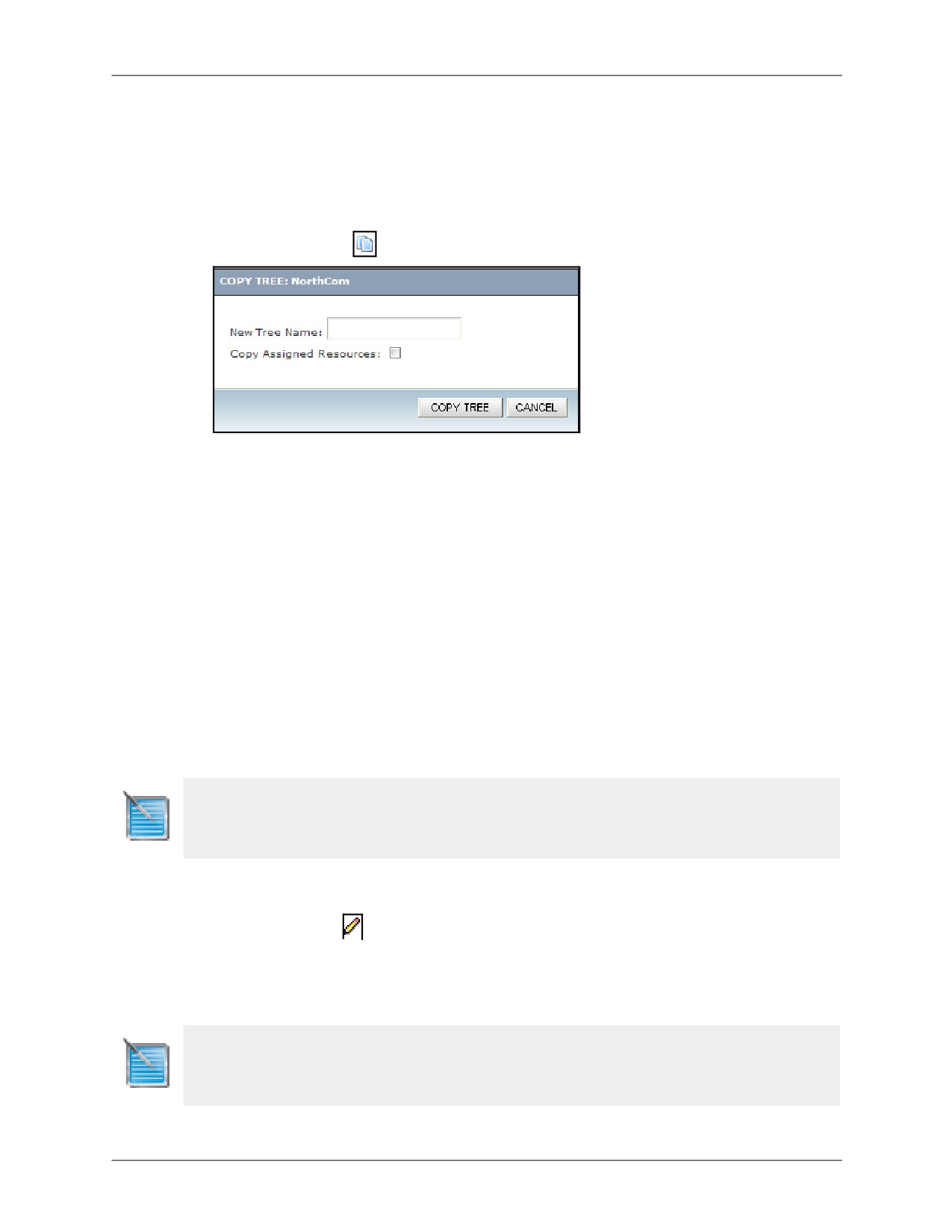
2. Click the Copy icon
corresponding to the desired tree.
Figure 16-6: Copy Existing Tree
3. In the prompt that appears, enter a name for the new tree you wish to create.
4. Select whether or not to include the resources assigned to the tree being copied. Manual
assessments are automatically included.
5. Click Copy Tree.
A new tree will be created under your Unit of Assignment using the structure and settings of the
tree selected to be copied. You will be taken to the CT Control Center where the tree you
created will be available for modifications.
16.3
Changing Tree Name and Details
Capability Trees are designed to be customizable. Consequently, they provide a variety of tools
that allow for the modification of each tree. The first involves making modifications to the tree
details. Once a tree has been created, details provided during the Capability Tree Wizard
process can still be edited in case you have made mistakes.
Note: Only the tree creator and the unit administrator or unit commander role for the unit of assignment
are allowed to edit a tree.
To change the name or details of a tree:
1. Access the CT Control Center by selecting Utilities | Capability Trees.
2. Click the Edit icon
next to the name the tree you wish to modify. You will be taken to the
Tree Wizard screens where the data for the selected tree was originally entered. From here,
you will be able to make certain modifications such as the tree name, display options, and
associated mission.
3. Click Save Tree when finished and your updates are saved.
Note: Options such as assigned orgs for org trees or assigned missions for missions are not editable as
these are directly linked with the database. It is advised if you need to change these options, it is easy to
simply delete the ole tree and create a new org or mission tree.
DRRS Software User Manual (SUM) 4.5.12
16-7
Changing Tree Name and Details
Chapter 16: Creating Trees
This Page Intentionally Left Blank.
16-8
DRRS Software User Manual (SUM) 4.5.12
Chapter 17: Working With Trees
Chapter 17: Working With Trees
This chapter discusses the options available once a tree has been created. Topics covered
include:
• Viewing the Setup page for each tree. This allows for the following actions:
•
Modify tree structure by adding new ones or repositioning existing nodes
•
Editing Node Details
•
Assigning resources to a node
• Viewing the final product on the Assessment page
• Setting trees to Shared for all users in DRRS to view
• Deleting a Tree
Note: You may only make changes to a tree that you have created (unless you are the Unit Administrator
or Unit Commander, in which case you will have rights to all trees within your primary unit of assignment).
DRRS Software User Manual (SUM) 4.5.12
17-1

View the Tree Structure
Chapter 17: Working With Trees
17.1
View the Tree Structure
Once you have a created a tree, the first thing you need to do is view the tree structure to see
what has been created.
To view a tree structure:
1. Access the CT Control Center by selecting Utilities | Capability Trees.
2. Click the hyperlinked name of the tree you wish to modify. This will take you to the
Assessment view by default. You can always tell which view is active by looking at the Tree
View dropdown in the CT Toolbar.
Figure 17-1: Tree View Dropdown
3. Select the Setup view. The Setup view shows each of the individual tree nodes that were
created using the Tree Wizard or Copy Tree functionality. For example, the Organization
Tree will have a single node at the top representing the parent org and a plus sign. Clicking
this plus sign will reveal all subordinate children. Please note that only one subordinate
node can be opened at a time to reveal its child nodes.
Figure 17-2: Tree Setup View
This following sections detail each action that can be performed from the Setup View:
• Modify tree structure by adding new ones or repositioning existing nodes
• Editing Node Details
• Assigning resources to a node
17-2
DRRS Software User Manual (SUM) 4.5.12
Chapter 17: Working With Trees
View the Tree Structure
17.1.1
Adding Nodes to an Existing Tree
This is especially for custom trees as there will only be one node created when you first access
the Setup page.
To add nodes to an existing tree:
1. Click the Add button on the node to insert a subordinate one. The new node will appear
directly below the node you clicked the Add button in.
2. Enter a name for the new node as the default is “TITLE”. To do this, simply type over this
text and click the Enter button.
3. Optionally, you can edit the color of the new node, by selecting a new one using the node
color dropdown. All colors displayed are web safe and present equally well in all internet
browsers.
4. Continue adding nodes until the desired structure is displayed. You may add as many
nodes and tiers of nodes as needed. To assist you, the new node will display with a yellow
border (for five seconds) and the page will reposition to focus on the new node.
5. If you accidentally add one too many nodes, click the “X” button in the node’s upper-right
corner to remove it.
6. Existing tiers of nodes can be expanded or collapsed by clicking the “+” or “-“ button in the
parent node.
Note: The organizational structure is saved automatically as you create it. You may return and
modify it at any time.
17.1.2
Repositioning Nodes in a Tree
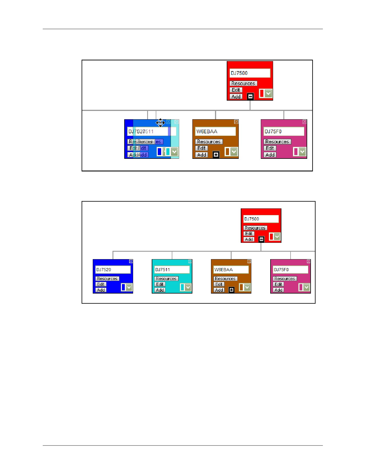
Tree nodes may also be moved around within a structure by dragging them and dropping them
into the desired location. By doing so, you may modify your tree to fit any hierarchical structure
you need.
To reposition a node in a tree:
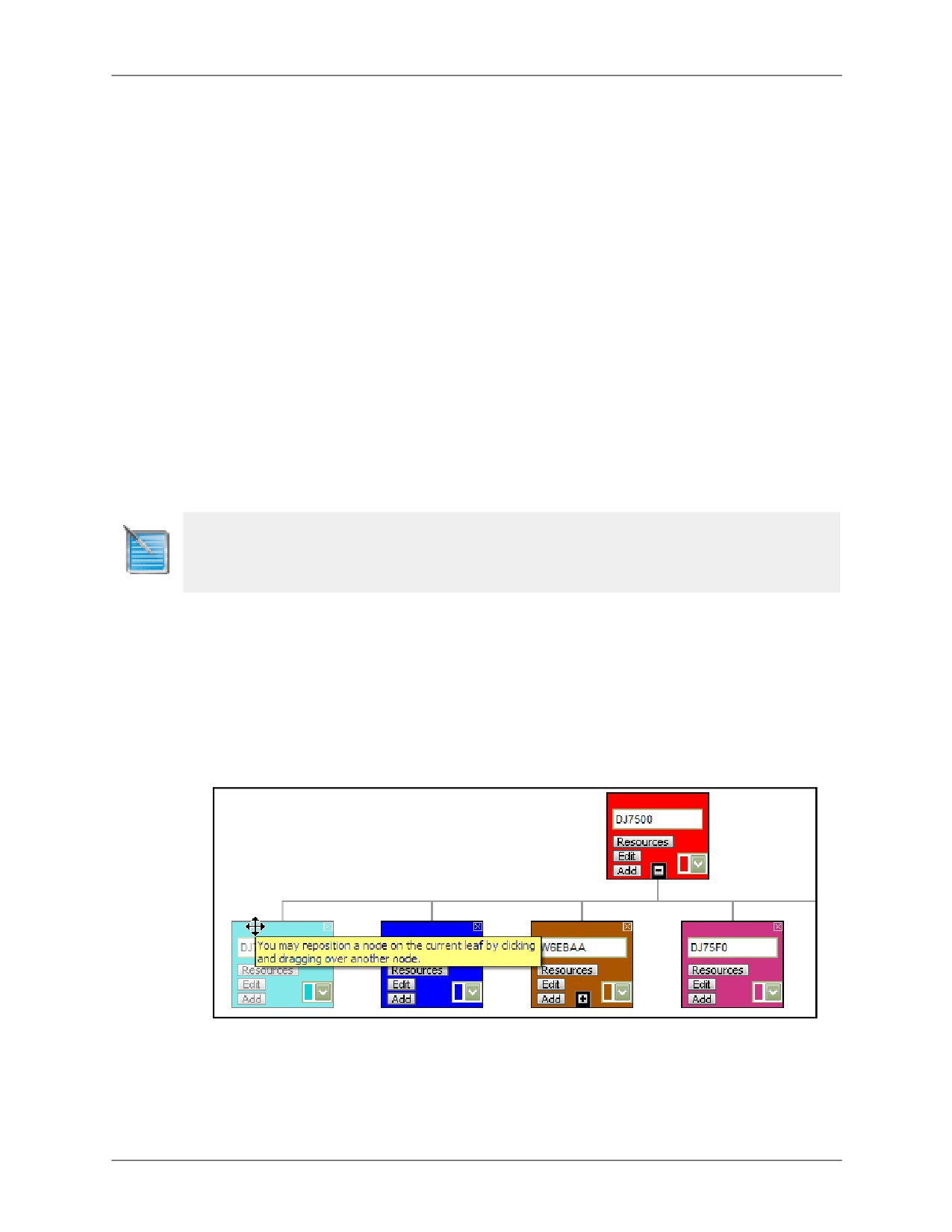
1. Click the left mouse button and hold your mouse over the node you would like to move. You
will see your normal mouse pointer change to a 4 direction cursor.
Figure 17-3: Drag Node: Step 1
DRRS Software User Manual (SUM) 4.5.12
17-3
View the Tree Structure
Chapter 17: Working With Trees
2. Drag your mouse (and the node) over the spot you would like to move it to. Please note that
it may take one or two tries before you get the hang of where to drop the node.
Figure 17-4: Drag Node: Step 2
3. Once your mouse is where you would like to place the node, let go of the left mouse button
and the node will drop into place.
Figure 17-5: Drag Node: Step 3
4. Repeat as necessary.
17-4
DRRS Software User Manual (SUM) 4.5.12

Chapter 17: Working With Trees
View the Tree Structure
17.1.3
Editing Node Details
Each node supports the ability to add details that are then displayed on the Assessment page
for use during demonstrations or analysis.
To add details to a node:
1. Click the Edit button on a node. The Edit Node pop-up window displays.
Figure 17-6: Edit Node Details Window
A unit should be assigned to each of the nodes in the structure. These units will serve as the
assessment representatives for the node they are assigned to. If the unit assigned to a node
has an ESORTS mission assessment value for the tree’s associated mission, that value will
be displayed in the node on the Assessment page. (This is not applicable for a custom tree
as there is no associated mission, however you can still add a unit for display purposes).
Note: If you have built a mission or org tree, please be aware that you could overwrite the automatic data
entry. Please ensure that you would like to overwrite this value before attempting to do so as there is no
way to roll back to a previous node state.
1. In the Assigned Unit field, enter all or part of the UIC, ANAME, or LNAME of the unit you
wish to assign to this command, click the Add Wildcards link and then click Search.
2. From the search results, click on the desired unit and click Select.
3. Enter a Required value for the node. This allows you to specify how many resources should
be assigned to the node. This is useful if you have chosen to display the Required and Filled
display options in the tree wizard as it will serve as a direct comparison between what you
wanted to assign (Required) and what was actually assigned (Filled).
4. You may select a current readiness assessment value for this unit and an “as of” date. If an
ESORTS mission assessment value already exists in the system for this unit based on the
selected mission, the value entered here will override it. You may also leave this field blank
to keep the original ESORTS mission assessment value or, if one does not exist, to not
display a value.
DRRS Software User Manual (SUM) 4.5.12
17-5
View the Tree Structure
Chapter 17: Working With Trees
5. You may select a projected readiness assessment value for this unit and select an “as of”
date. The same rules as the current readiness assessment apply to this field, only based on
the ESORTS projected mission assessment value.
6. You may attach any file up to 10mb in size using the Browse and Upload buttons in the File
Attachment section.
7. Enter any pertinent text remarks that apply to the entire node. You have a 1000 character
limit.
8. Click Save. The page refreshes and the tree node is updated. These results display on the
Assessment page.
9. Repeat this process for each node in your tree.
17.1.4
Assigning Resources to a Tree Node
Once a tree’s structure has been edited and finalized, the last step is to assign resources to the
nodes of that tree.
Whether you are creating a mission structure, organization structure, or a custom structure,
resources represent a crucial part of the Capability Tree. Resources include the units,
equipment, and personnel assigned to perform specific tasking in a mission, report to an
organization, etc.
To assign resources to a tree node:
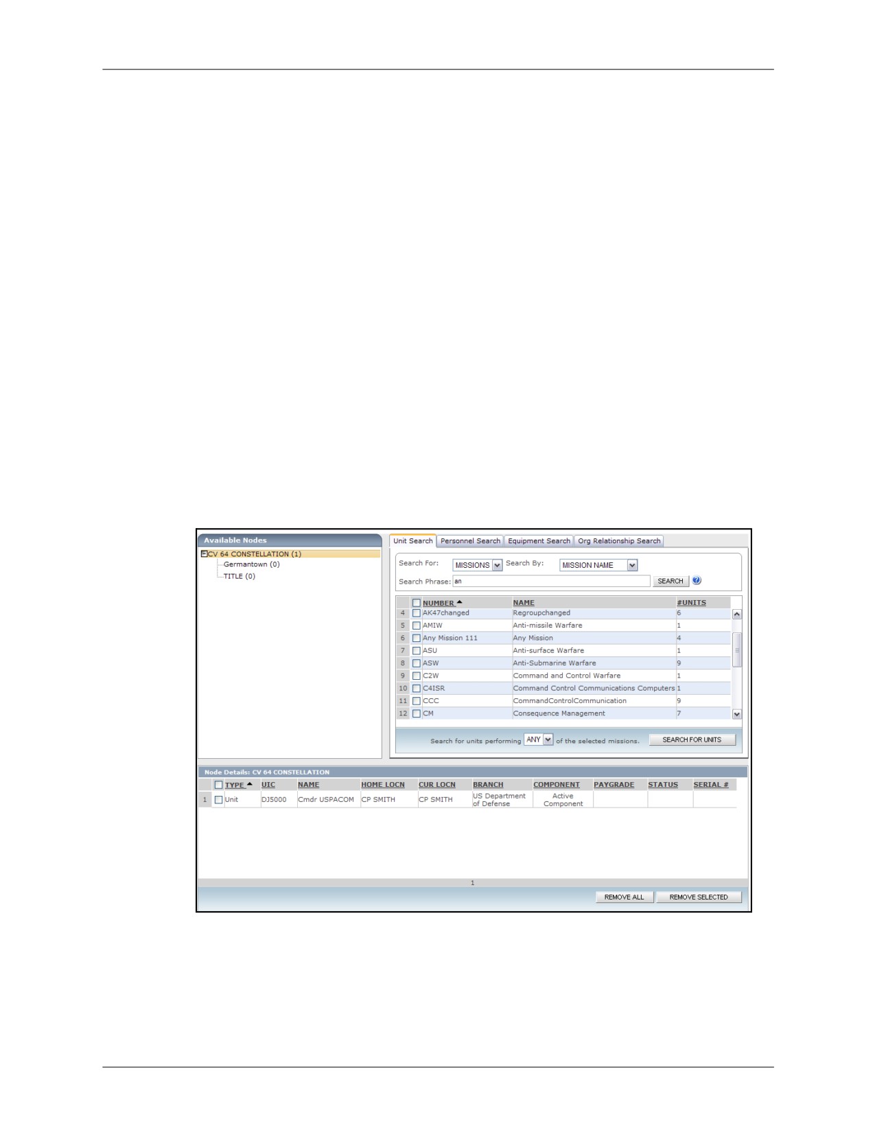
1. Open the tree view and select the Assign Resources tree view which is used to detail the
resources assigned to each node in a tree.
Figure 17-7: Assign Resources View
2. In the Available Nodes panel on the left, the list of nodes corresponds to the tree you were
viewing. You have the option of selecting any node in the tree to assign resources to.
3. Next, using the Unit Search, Personnel Search, Equipment Search, or Org Relationship
Search tabs, locate the units, personnel, and/or equipment to be assigned to the selected
node.
17-6
DRRS Software User Manual (SUM) 4.5.12
Chapter 17: Working With Trees
View the Tree Structure
Unit Search
a.
Click the Unit Search tab (if not already selected by default).
b.
Select an option from the Search For field. Your selection will change the options
available in the Search By field. The selection options are shown below:
•
Units
•
UIC/ANAME: Search for units with all or part of a specific UIC or AName.
•
SRC: Search for units with a particular Standard Requirement Code.
•
TPSN: Search for units assigned a specific Troop Program Sequence Number.
•
UTC: Search for units of a certain Unit Type Code.
•
Location Code: Search for units assigned a specific Location Code.
•
Tasks
•
Task Number: Search for tasks using all or part of the task number.
•
Title AND Description: Search for tasks containing your search phrase in both
the title and the description.
•
Title OR Description: Search for tasks containing your search phrase in either
the title or the description.
•
Missions
•
Mission Name: Search for missions using all or part of a mission name.
•
Mission Number: Search for missions using all or part of a mission number.
c.
In the Search Phrase field, enter all or part of the phrase to search for. Wildcards are
automatically added to your search criteria to increase the number of results that are
returned.
d.
Click Search. The units matching your search criteria are displayed. Clicking the UIC or
AName of any of the results will open the Current Unit Status details for that selection.
e.
Select the checkboxes next to the unit(s) you would like to add and then click the Add
Selected button. You are notified whether or not the selected resources were
successfully added to the node. Search results will remain displayed on the page until
another unit search is performed.
Personnel Search
a. Click on the Personnel Search tab.
b. Select an option from the Search By field. The options are:
•
Full Name: Last Name, First Name is the format.
•
Code/Description: Search by MOS, OCC, NEC/NOBC, or ASI.
•
UIC/ANAME: Find personnel associated with a specific unit.
c. In the Search Phrase field, enter all or part of the phrase to search for. Wildcards are
automatically added to your search criteria to increase the number of results that are
returned.
d. Click Search.
•
For Full Name searches, the personnel matching your search criteria are displayed.
Proceed to the next step. Clicking the UIC or Unit Name of any of the results will
open the Current Unit Status details for that selection.
DRRS Software User Manual (SUM) 4.5.12
17-7
View the Tree Structure
Chapter 17: Working With Trees
•
For Skill Code searches, the skill codes matching your search criteria are displayed
and you must now select the skill codes within which to search for personnel. Do
this by selecting the desired skill codes and clicking the Search for People button.
The personnel matching your search criteria are displayed. Clicking the UIC or Unit
Name of any of the results will open the Current Unit Status details for that
selection.
e. Select the checkboxes corresponding to the personnel you would like to add and then
click the Add Selected button. You are notified whether or not the selected resources
were successfully added to the node. Search results will remain displayed on the page
until another personnel search is performed.
Equipment Search
a. Click on the Equipment Search tab.
b. Select an option from the Search By field. The options are:
•
Current Location: Search for equipment that is in a particular location. This search
works for Location Codes.
•
Description: Search for equipment using a general description
•
Serial #: Serial number of specific piece of equipment
•
Type: Search for a specific type of equipment across the Services
•
UIC: Search for all of the inventory for a specific UIC.
c. In the Search Phrase field, enter all or part of the phrase to search for. Wildcards are
automatically added to your search criteria to increase the number of results that are
returned.
d. Click Search. The equipment matching your search criteria are displayed. Clicking the
UIC of any of the results will open the Current Unit Status details for that selection.
e. Select the checkboxes corresponding to the equipment you would like to add and then
click the Add Selected button. You are notified whether or not the selected resources
were successfully added to the node. Search results will remain displayed until another
equipment search is performed.
Org Relationship Search
The Org Relationship search allows you to search a single unit and return all of the children
of that unit, depending upon the relationship that you are looking for.
a. Click the Org Relationship Search tab.
b. Select a Service branch to filter your results.
c. Select a Component to filter your results further.
d. Choose a Relationship to return your results by (ADCON, OPCON, or COCOM)
e. Enter an exact UIC. Unlike other search criteria, you must enter the exact UIC you are
looking for.
f.
Click Search. The units matching your search criteria are displayed. Clicking the UIC or
AName of any of the results will open the Current Unit Status details for that selection.
g. Select the checkboxes next to the unit(s) you would like to add and then click the Add
Selected button. You are notified whether or not the selected resources were
successfully added to the node. Optionally, you can click the Add All button to add all of
the search results to the node. Search results will remain displayed until another org
relationship search is performed.
17-8
DRRS Software User Manual (SUM) 4.5.12
Chapter 17: Working With Trees
View the Tree Structure
TPFDD Search
The TPFDD search provides the ability to enter your Collaborative Force-Building, Analysis,
Sustainment, and Transportation (CFAST) system username and an OPLAN ID to generate
a TPFDD job to retrieve units to add to your Capability Tree.
a. Click the TPFDD Search tab.
b. Enter your CFAST username in the Username field.
c. Enter an OPLAN ID in the Plan Number field.
d. Click Get Units. A TPFDD job is started and when it is finished processing the
corresponding units are returned.
4. Continue selecting nodes and/or adding resources as needed. You may also remove
resources using the Remove Selected button in the Node Details panel at the bottom.
DRRS Software User Manual (SUM) 4.5.12
17-9

Assessment View
Chapter 17: Working With Trees
17.2
Assessment View
The final tool of the Capability Trees module is the Assessment view. This view is where the
resources assigned and their ESORTS mission readiness assessments (or your own manual
assessments entered in Edit Details) come together in a visual display of a complete structure.
To access the Assessment view:
1. Access the CT Control Center.
2. Click the hyperlinked name of the tree you wish to view. By default, the Assessment view
displays.
This view is used to illustrate the “final” product and is extremely useful for demonstrations
or deep analysis of plans. It is designed primarily to be a read-only view where the
resources and readiness in each node can be reviewed.
Figure 17-8: Tree Assessment View
3. For ease of use, only the first level of the tree is expanded by default and the tree is shown
at 100% zoom level. To expand or collapse a node’s children, click the + sign or - sign,
respectively. To tweak the zoom, use the selector in the CT Toolbar. The view is based on
the display options selected in the Tree Wizard. Click the Edit icon in the CT Toolbar to
update these options. Once the view has been customized, the tree structure can be viewed
in more detail using the following options:
• Click the assessment icon (Y, Q, N) to open the ESORTS Mission Assessment screen.
This does not apply for Manual Assessments.
• Holding your mouse cursor over the “i” in the lower-left corner of any node will display a
pop-up showing the assessment breakdown of the units assigned to that node.
• Clicking the hyperlinked UIC in any of the nodes will open a pop-up displaying the
Current Unit Status information for that organization.
17-10
DRRS Software User Manual (SUM) 4.5.12

Chapter 17: Working With Trees
Assessment View
17.2.1
Analyze Resources
The last step in viewing the Assessment involves the Resource Analysis view. This view
provides a data-driven analysis of assigned units, personnel, and equipment.
To access Resource Analysis:
1. Ensure you are on the Assessment view.
2. Place your mouse over the lower-left corner of any node for 2 seconds. The Node Overview
popup will appear, showing the unit assigned to this node, the number of resources
required, the overall and projected readiness assessments, lowest assessment value, as
well as a breakdown of assigned resources by Service. You can also click the File
Attachment hyperlink to view any files that have been uploaded to this node.
Figure 17-9: Node Overview Popup
3. Click either the View All Resources link or one of the hyperlinked Service names if you
prefer to filter the data to view only those assigned to any one Service. This will open the
Resource Analysis screen which provides a detailed look at all resources assigned to this
node (organized by tabs). Information provided in this view includes UIC and AName, CUR
and Home LOCN, Posture, Status, and more (much of this data is derived from direct entry/
approval in the Current Unit Status tool).
Figure 17-10: Resource Analysis Screen
4. Use the Filter By: at the top of the page to select resources for a particular node. If
everything looks good, you are ready to share your tree with the rest of the DRRS
community.
DRRS Software User Manual (SUM) 4.5.12
17-11
Setting Trees to Shared
Chapter 17: Working With Trees
17.3
Setting Trees to Shared
The final step creating a tree is to share it with the rest of the DRRS community. Up to this point,
you were the only person who could see your “Private” tree in the CT Control Center.
To share a tree:
1. Ensure that you have reviewed the tree and wish to share all of its details and resources
with other users.
2. Access the Control Center by selecting the Home link in the CT Toolbar (or you can choose
Utilities | Capability Trees from the Main menu).
3. You will see a list of all trees assigned to your unit of assignment. Next to each tree name is
a column for Status. The tree you just created and approved should have a setting of
“Private”.
4. Click this “Private” hyperlink and then review and click OK to the message prompt that
displays.
5.
The tree status is set to “Shared”. Now all users in DRRS can view your tree.
17.3.1
Set a Tree back to Private
If you need to make substantial edits to your tree, you can always select the “Shared” hyperlink
to set it back to “Private”. You will note that you can only set the Shared/Private status for trees
that you have created.
Note: If you make a tree Private while another DRRS user is viewing it, the user may experience a delay
on clicking anywhere in the tree. Once the page is refreshed, the user will be returned to the CT Control
Center and the tree they were just viewing will be invisible as it is now Private. The DRRS development is
working on a way to gracefully display a message to the user informing them of this change in status.
17.4
Deleting a Tree
You can only delete trees that you have created. It is advised that you set the status to “Private”
for any trees you wish to delete. To delete a tree:
1. Access the CT Control Center and click the delete icon (X) next to the tree you wish to
remove.
2. A confirmation box appears and once you confirm, the tree is permanently deleted.
17-12
DRRS Software User Manual (SUM) 4.5.12
Chapter 18: Frequently Asked Questions
Chapter 18: Frequently Asked Questions
This collection of frequently asked questions (FAQ) provides brief answers to common
questions about the DRRS application.
DRRS Software User Manual (SUM) 4.5.12
18-1
General FAQ
Chapter 18: Frequently Asked Questions
18.1
General FAQ
18.1.1
Why do I see (or not see) the Top Concerns tab on the CUS main page?
If you are on another unit’s Subordinates list, you will see the Top Concerns tab on your main
CUS page. From here you will then have access to Deficiencies and Lessons Learned. See
Chapter 12: Readiness Dashboard (JFRR) for more information.
18.1.2
Will My Pop-Up Blocker Interfere with DRRS?
Many DRRS tools utilize pop-up windows. In order to achieve optimum results, please disable
all pop-up blockers prior to starting the software.
18.1.3
Why are my results not displaying in MS Excel using Internet Explorer?
This is a Microsoft issue that can be easily resolved by configuring Internet Explorer to allow you
to view your results in Word or Excel.
To configure your Internet Explorer:
1. Click Start | My Computer.
2. On the Tools menu (or the View menu), click Folder Options (or click Options).
3. Click the File Types tab.
4. In the Registered file types list, click the specific Office document type (for example,
Microsoft Excel Worksheet), and then click Advanced (or click Edit).
5. In the Edit File Type dialog box, click to clear the Browse in same window checkbox (or
clear the Open Web documents in place checkbox).
6. Click OK.
18.1.4
Why am I not able to export to Excel?
This issue may be caused by an Internet Explorer setting that disables automatic prompting for
downloads such as Excel file exports. To resolve this issue:
1. Open Internet Explorer.
2. Select Tools | Internet Options.
3. Open the Security tab.
4. Click Custom Level.
5. Scroll down to the Downloads section and ensure that Automatic Prompting for Downloads
is set to Enabled.
18.2
User Access FAQ
18.2.1
Why can’t I access Joint Readiness map from the Portal?
Although the Joint Readiness map displays in the Portal home page, users still need access
role permissions. For a detailed list of user roles and permissions, please see the DRRS
Software Administration Manual (SAM).
18-2
DRRS Software User Manual (SUM) 4.5.12
Chapter 18: Frequently Asked Questions
User Account FAQ
18.3
User Account FAQ
18.3.1
How do I change my Username or Password?
A Username cannot be changed. If you are having problems, please contact your administrator.
To change your password, select My Profile from the DRRS Support menu (upper-right
corner). In the Password and Confirm Password fields, enter your new password. Please
review the following rules:
PASSWORD RULES:
• At least 8 characters
• Maximum is 25 characters
• Cannot contain spaces
• Must include at least 1 number (1, 2, 3…)
• Must include at least 1 lowercase alpha character (a, b, c…)
• Must include at least 1 uppercase alpha character (A, B, C…)
• Must include at least 1 special character
• Can contain the following special characters: (! @ # $ % ^ & * - _ . ?)
• Case-sensitive
18.3.2
How do I reset my Password?
If you forget your password, perform the following steps to have it reset:
1. Select Forgot Password from the DRRS Log-in screen.
2. Enter all the required information. Ensure that this is the exact information used on your
user account.
3. Click Request New Password. The information is sent to DRRS Product Support and you
will receive a message at your classified email address notifying you of your new password.
18.3.3
How do I unlock my account?
After three failed attempts to log-in to DRRS, your account will be locked. The only way to
unlock your account is to have a user with administrator rights enable (Enable = True means
you are active) your account again. To do this, please contact DRRS Product Support.
A confirmation message is sent to your classified email address once a DRRS unit administrator
resets your account.
18.3.4
Why am I unable to change my unit of assignment?
ESORTS no longer supports the ability for users to have more than one unit of assignment
(formerly known as “unit of interest”). This value is entered upon first logon to DRRS. To change
this value, contact your ESORTS Unit Admin or DRRS System Admin.
DRRS Software User Manual (SUM) 4.5.12
18-3
Joint Readiness FAQ
Chapter 18: Frequently Asked Questions
18.4
Joint Readiness FAQ
18.4.1
Why aren’t my missions showing up in Joint Readiness?
This problem has been fixed. You can now select a mission from the Add Operation menu. Unit
Readiness Assessment data for the selected mission is updated in real-time.
18.4.1.1
Why can’t I see the Add Forces button in Force Analysis?
There are two reasons:
• The scenario is loaded with TPFDD data. To undo this, access the Operations page
and delete the TPFDD.
• You are trying to edit the JTF, CFC, or CBRNE icon. This view only shows a read-only
view of all units in the current scenario force.
18.4.1.2
Are JTF, CFC, and CBRNE Operation Types Interchangeable?
JTF and CFC operations may be swapped anytime using the Edit Operations button. CBRNE
are not interchangeable with any other operation type.
18.5
Data FAQ
18.5.1
How can I view all data sources currently feeding the DRRS application?
Data Sources is a detailed data source viewer which retrieves the description, timestamp/
update information, and security classification for each data source feeding into the DRRS
application. It is important to understand the following:
• Last Provided: The last date the data was sourced to DRRS.
Depending on your user privileges, this feature might not appear in your menu. This feature is currently
only accessible to “beta” users for product improvement purposes.
To access system info, select Utilities | Data Sources from the Main Menu. The Data
Providers Viewer page appears. Notice the tab control at the top of the screen. The following
two tabs are displayed:
• Data Providers Viewer: Contains the details of the selected data source including the
classification status and the functional areas encompassed by this particular source. To
change the displayed data source, select a new source from the Data Providers menu.
• Functional Areas: This is a reverse-engineering of the preceding tab in that you select
the functional area (Personnel, Mobilization, Equipment, etc.) and the resulting display
details all of the relevant data sources feeding into it.
18.6
Portal FAQ
The following section answers frequently asked questions users have when customizing the
portal.
18-4
DRRS Software User Manual (SUM) 4.5.12
Chapter 18: Frequently Asked Questions
Portal FAQ
18.6.1
What is a hidden web part? How do I un-hide my web part?
A hidden web part is a web part that is closed but not deleted. You can temporarily close any
web part by clicking the Close icon.
Tho view a list of Hidden web parts:
1. Select Portal Tools | Add/Remove Web Parts.
2. Select the Currently Hidden Web Parts link at the top of the editor. The list of hidden web
parts displays.
To un-hide a web part:
1. Select Portal Tools | Edit Web Parts.
2. Select the Edit icon for the web part you would like to un-hide.
3. Click the plus sign to access the Appearance area.
4. Ensure the Hidden button is not checked.
18.6.2
How do I remove the menu title and border around my web part?
1. Select Portal Tools | Edit Web Parts. Optionally, you can select the Edit icon directly from
the Home page if it displays in the web part title bar.
2. Select the Edit icon for the web part you would like to un-hide.
3. Click to access the Appearance area.
4. Set the Chrome Type: field to None.
5. Click OK. The page refreshes and the web part displays without a title or border. The
Chrome Type: field controls the visual display for each web part.
18.6.3
How many Unit Mission List Web Parts can I add?
You can add as many Unit Mission Web Parts as you like. You can personalize each one with a
custom title and change the UIC being displayed for each one.
To add a Unit Mission Web Part:
1. Select Portal Tools | Add/Remove Web Parts.
2. Select the Unit Mission List web part.
3. Choose the zone (area of the portal) you would like to display the Mission List in.
4. Click Add.
5. Click the Edit icon on the Mission Details web part.
6. Enter the UIC or Aname and then click Search. Highlight the unit from the Search Results
then click Select (optionally you can select the Use Unit of Assignment checkbox).
7. Click the plus sign to access the Appearance area. Change the title text to reflect your
needs.
8. Click OK. The page refreshes and the web part displays.
DRRS Software User Manual (SUM) 4.5.12
18-5
Portal FAQ
Chapter 18: Frequently Asked Questions
18.6.4
What is an RSS viewer? Any suggestions on how to configure?
RSS stands for Really Simple Syndicate. It is a family of web feed formats used to publish
frequently updated content such as news headlines or blog entries. This is especially useful for
sites that frequently publish new or updated content such as Fox or CNN news. An RSS
document, which is called a "feed", contains either a summary of content from an associated
web site or the full text. RSS makes it possible to keep up with your favorite web sites in an
automated manner that's easier than checking them manually.
If you are on the SIPRNet, access a search engine with keyword “RSS.” This should return a
number of results. Creating an RSS viewer provides information on intelligence and surveillance
that is conveniently summarized for your review on the DRRS Portal.
To set up an RSS viewer:
1. Select Portal Tools | Add/Remove Web Parts.
2. Select the RSS Viewer web part.
3. Choose the zone (area of the portal) you would like to display the RSS Viewer in.
4. Click Add.
5. Click the Edit icon on the RSS Viewer.
6. Enter the URL for the RSS feed. This is always available from the site that is publishing the
content. Note that you must use an actual RSS link, simply entering a URL will not automatically
display content. For more information, see the Portal FAQ.
7. Leave the option set to Auto scroll unless you prefer to manually navigate the list (this is
sometimes useful for really large feeds).
8. Click the plus sign to access the Appearance area. Change the title text to reflect your
needs.
9. Click OK. The page refreshes and the web part displays. If the RSS Feed is working, you
will begin to see content inside the web part.
18.6.5
What is the moving red dot on the Readiness Dashboard image?
The red dot is a only an image animation.
18.6.6
How do I set the watch list?
To modify the watchlist that displays on your DRRS Portal home page, follow the steps below.
1. Click Utilities | Group Builder. The Group Builder displays.
2. Select a group from the Custom Groups menu. The group is highlighted in grey.
Note: You cannot select a system group from the left-side of the screen.
3. Click the Set As Watchlist button at the bottom of the Custom Group menu. The page
refreshes and the selected group is now followed by the text (Watchlist). This value can be
changed at any time by repeating the above steps.
18-6
DRRS Software User Manual (SUM) 4.5.12
Chapter 18: Frequently Asked Questions
Portal FAQ
18.6.7
How do I set a group as suborinates?
To set your subordinates group:
1. Click Utilities | Group Builder. The Group Builder displays.
2. Find and select the group you wish to set as your subordinate.
3. Click the Set as Subordinates button located in the Group Controls.The subordinates group
set here is your default view when using the Readiness Dashboard copy functionality.
18.6.8
How do i create an Image List that visually links me to different websites?
An effective way to present links is to use image links instead of plain text. In this example, we
will show you how to create a news link web part that links to popular news sites.
1.
Locate the three sites:
2.
Next, we need to locate the images for each site. This is easily accomplished by opening
each site and right-clicking on the image icon for the web site. When the menu appears click
Properties and then copy the URL for the image.
3.
Select Portal Tools | Add/Remove Web Parts.
4.
Select the Image List web part.
5.
Choose the zone (area of the portal) you would like to display the Image List in. Left is a
good choice to start from as you can always drag the web part to a new location.
6.
Click Add.
7.
Click the Edit icon on the Image List you just added.
8.
Enter the URL for the image (Image URL) and corresponding website (Link URL).
Optionally, you can add tooltip text (Tooltip) to display when you hover over the images.
9.
Click Add Link.
10. After adding each link, click the Property Grid and set the default display for the images
(Horizontal = across, Vertical = up/down).
11.
Click the plus sign to access the Appearance area. Change the title text to reflect your
needs or set the Chrome Type: to whatever you choose. For this example we will set
Chrome Type: to border only.
12. Click OK. The page refreshes and the web part displays.
13. Click Portal Tools | Personal View to see the final product. Now, just edit the links and
image URLs to whatever you would like to display and you have your own custom created
list.
DRRS Software User Manual (SUM) 4.5.12
18-7

Portal FAQ
Chapter 18: Frequently Asked Questions
Figure 18-1: Portal News (Example)
18.6.9
What is the difference between an Image List and an Image Viewer?
Unlike the Image List web part described in the previous question, you can only add one image
to the Image Viewer web part although there is no limit to the number of Image Viewer web
parts you can add.
Another key difference between them is that the Image Viewer displays text and the image.
18.6.10
Why does drag and drop crash my browser?
Older browsers and older computers may have trouble with drag and drop of web parts. If you
are having this problem, perform the following steps.
1. Select Portal Tools | Edit Web Parts. Optionally, you can select the Edit icon directly from
the Home page if it displays in the web part title bar.
2. Select the Edit icon for the web part you would like to move. The Edit Web Parts menu
appears. The name of the web part you are editing displays in the Currently Editing: area.
3. Open the Layout area.
4. Leave Chrome State: controls set to normal.
5. Specify the Zone: that the web part should appear in, instead of dragging and dropping web
parts.
•
Top Web Part Zone: top of the screen and covers the entire width.
•
Left Web Part Zone: left side of the screen. This and the middle zone are the most
effective for common resolution of 1024 x 768.
•
Middle Web Part Zone: middle area of screen although at 1024 x 768 this is
effectively the “right side” of screen unless you prefer to horizontal scroll.
•
Right Web Part Zone: effective for creating a third web part zone at resolutions of
1280 x 1024 or higher.
•
Bottom Web Part Zone: Bottom area is effectively “pushed” down by the number of
web parts above it.
6. Set Zone Index: to a number that indicates its order web part should display (0 = top, 1
equals second from the top, 2 = third from the top, etc.)
18.6.11
Can I edit web parts directly from the Home page?
Optionally, you can select the Edit icon directly from the web part if it is displayed in the title bar.
This performs the same action as clicking Edit Web Parts then selecting the Edit icon. This
manual presents the “longer” way each time as it ensures discussion of all web parts. Not all
web parts have the Edit icon displayed on the Home page.
18.6.12
Why is My Links empty when I first access the DRRS Portal?
My Links is for your personal links. You will need to enter them using the steps outlined in 3.2.6
Managing My Links.
18-8
DRRS Software User Manual (SUM) 4.5.12
Glossary
Glossary
A | B | C | D | E | F | G | H | I | J | K | L | M | N | O | P | Q | R | S | T | U | V | W | XYZ
Alpha Numeric name assoc. with unit
A
AOC
AAW
Area of concentration
Anti-Air Warfare mission area
Active Duty for Training (ADT)
A tour of active duty which is used for training
Area of operations (AO)
members of the Reserve Components to
provide trained units and qualified persons to
An operational area defined by the joint force
fill the needs of the Armed Forces in time of
commander for land and naval forces. Areas
war or national emergency and such other
of operation do not typically encompass the
times as the national security requires.
entire operational area of the joint force
commander, but should be large enough for
Activity
component commanders to accomplish their
A unit, organization, or installation performing
missions and protect their forces.
a function or mission.
Area of responsibility (AOR)
ADT
The geographical area associated with a
Active Duty for Training
combatant command within which a
combatant commander has authority to plan
AFSC
and conduct operations.
Air Force Specialty Code
Army Service Component Command (ASCC)
Air Force Special Operations Component
Command responsible for recommendations
(AFSOC)
to the joint force commander on the allocation
The Air Force component within a joint force
and employment of Army forces within a
special operations component.
combatant command.
Air Force Special Operations Forces (AFSOF)
Army Special Operations Component (ARSOC)
Those Active and Reserve Component Air
The Army component within a joint force
Force forces designated by the Secretary of
special operations component.
Defense that are specifically organized,
Army Special Operations Forces (ARSOF)
trained, and equipped to conduct and support
special operations.
Those Active and Reserve Component Army
forces designated by the Secretary of Defense
AMO
that are specifically organized, trained, and
Ammunition Storage
equipped to conduct and support special
operations.
ADW
ASI
Aviation Data Warehouse
Additional skill identifiers
AFUTL
AS OF DATE
Air Force Task List
Identifies the as-of date of the most current
AMSRR
message
Aviation Maintenance & Supply Readiness
AS OF DTG
Reporting
As of Date, Time, Group
AMW
Auth
Amphibious Warfare mission area
Authorized or authorization
Aname
Availability date
DRRS Software User Manual (SUM) 4.5.12
G-1
Glossary
The date after notification of mobilization by
CINC
which forces at their home station or
Commander-in-Chief
mobilization station are available for
deployment.
CNO
Chief Naval Operations
B
CNRFC
Billet
Command Navy Reserve Force Command
A personnel assignment that may be filled by
CNSL
one person.
Commander Naval Surface Atlantic
Branch
COCOM
Branch of Service
Combatant Commands. See term below.
BUPERS
Bureau of Naval Personnel
Combatant Command (COCOM)
C
A unified or specified command with a broad
Capability
continuing mission under a single commander
established and so designated by the
The ability to execute a specified course of
President, through the Secretary of Defense
action.
and with the advice and assistance of the
Carrier Air Wing
Chairman of the Joint Chiefs of Staff.
Combatant commands typically have
also known as CVW.
geographic or functional responsibilities.
Two or more aircraft squadrons formed under
Operational control is inherent in combatant
one commander for administrative and tactical
command
control of operations from a carrier.
Combatant Commander
Carrier Striking Force
A commander of one of the unified or
A naval task force composed of aircraft
specified combatant commands established
carriers and supporting combatant ships
by the President.
capable of conducting strike operations.
Combat Readiness
CASCAT
Synonymous with operational readiness, with
CASREP (Casualty Report) Category
respect to missions or functions performed in
combat.
CASNUM
Commander's Concept
CASREP (Casualty Report) Number
See concept of operations.
CASREP
COMLANTFOR
Casualty Report
Commander, Atlantic Force
CBRNE
COMPACFOR
Chemical Biological Radioactive Nuclear
Explosive. Operation types designed to
Commander, Pacific Force
provide capabilities for mass decontamination
Component Command
and rescue
One of the subordinate organizations that
CDR
constitute a joint force. Normally a joint force
Commander’s Assessment
is organized with a combination of Service and
functional components.
CFC
Concept of operations (CONOPS)
Combined Forces Command
A verbal or graphic statement, in broad
CG ATN
outline, of a commander's assumptions or
Coast Guard Aids to Navigation mission area
intent in regard to an operation or series of
operations. The concept of operations
CGC
frequently is embodied in campaign plans and
operation plans; in the latter case, particularly
Coast Guard Overall
when the plans cover a series of connected
G-2
DRRS Software User Manual (SUM) 4.5.12
Glossary
operations to be carried out simultaneously or
DEF
in succession. The concept is designed to give
Deficiency (Numbered List)
an overall picture of the operation. It is
included primarily for additional clarity of
DEL
purpose.
Delete
Concept plan (CONPLAN)
or
An operation plan in concept format. Also
Deployability Indicates the deployability of
called operation plan.
personnel based on rates, training, personnel
Conditions
type, etc.
Those variables of an operational environment
DET
or situation in which a unit, system, or
Detachment
individual is expected to operate and may
affect performance.
DoD OCC
Department of Defense Occupational Codes
CONOPS
DRRS
see Concept of Operations.
Defense Readiness Reporting System
CONUS
DRRS-N
Continental United States
Defense Readiness Reporting System-NAVY
COOP
Date Time Group (DTG)
Contingency and Continuity of Operations
The date and time, expressed in digits and
Plan
time zone suffix, at which a message was
prepared for transmission. (Expressed as six
COP
digits followed by the time zone suffix; first pair
Common Operational Picture
of digits denotes the date, second pair the
hours, third pair the minutes, followed by a
COUNT
three-letter month abbreviation and two-digit
Total number of records
year abbreviation.)
CPF
DTG
Commander’s In Chief Pacific Forces
see Date Time Group definition.
CSA
DTMS
Combatant Command/Service/Agency
Digital Training and Management System
CSG
Carrier Strike Group
CV
E
Carrier Vessel
CVW
ELT
Carrier Air Wing
Enforcement Laws and Treaties
CUR
ELW
Current
Electronic Warfare
CurLocn
ENL
Current Location
Enlisted Personnel
ENL OH
Enlisted On-hand
D
EQP
Days Open
Equipment Resource status
Number of days a request has been open
EQP AL
DRRS Software User Manual (SUM) 4.5.12
G-3
Glossary
Equipment Allocated
Each force module in a plan is uniquely
identified by a three-character alphanumeric
EQP AO DATE
identifier called a force module identifier
Equipment As of Date
(FMID). This allows for each of the individual
elements of force modules to be linked
EQP FMC
together so that they can be tracked for
Equipment Fully Mission Capable
planning purposes.
EQP NMC
Force sourcing
Equipment Not Mission Capable
The identification of the actual units, their
origins, ports of embarkation and movement
EQP OH
characteristics to satisfy the time-phased force
requirements of a supported commander.
Equipment On-Hand (given in Percentage)
FRP
EQP PMC
Fleet Rotation Plan
Equipment Partially Mission Capable
FSO
EQUIP DESC
Fleet Support Operations mission area
Equipment Description
Functional plans
ESG
Plans involving the conduct of military
Expeditionary Strike Group
operations in a peacetime or permissive
ESORTS
environment developed by combatant
commanders to address requirements such as
Enhanced Status of Resources and Training
disaster relief, nation assistance, logistics,
System.
communications, surveillance, protection of
Automated, near real-time readiness reporting
US citizens, nuclear weapon recovery and
system that provides performance output
evacuation, and continuity of operations or
standards and current readiness status for
similar discrete tasks. They may be developed
operational forces and defense support
in response to the requirements of the Joint
organizations in terms of their ability to
Strategic Capabilities Plan, at the initiative of
perform their mission essential tasks.
the combatant commander, or as tasked by
Establishes a relationship between resource
the supported combatant commander, Joint
and training inputs and readiness to perform a
Staff, Service, or Defense agency. Chairman
specific MET based on standards established
of the Joint Chiefs of Staff review of
by the parent DoD component.
combatant commander-initiated plans is not
normally required.
EST DATE
Estimate Date of Repair
G
F
GCCS-M
Global Command and Control System -
Feasibility
Maritime
Operation plan review criterion. The
GFM Org
determination as to whether the assigned
tasks could be accomplished by using
Global Forces Management Org Server. This
available resources.
provides authoritative organizational data to
DRRS.
FFC
GIS
Fleet Forces Command
Geographical Information Systems
FIRP
GSORTS
Fleet Intelligence Readiness Program
Global Status of Resource and Training
FMID
System
Force Module Identification
GUI
G-4
DRRS Software User Manual (SUM) 4.5.12
Glossary
Graphical User Interface
ISR
Intelligence, Surveillance and
Reconnaissance
ITAPDB
H
Integrated Total Army Personnel Database
HQMC
Headquarters Marine Corps
J
I
JAOP
IEEE
Joint Air Operations Plan. A plan for a
Institute of Electrical and Electronics
connected series of joint air operations to
Engineers
achieve the joint force commander's
ILAN
objectives within a given time and joint
operational area.
Integrated Local Area Network
JC2
ILS
Joint Command and Control
Integrated Logistics Support
JCA
IMR
Joint Capabilities Area
Individual Material Readiness
JCAS
or
Joint Capability Assessment
Immunizations and Medical Readiness
JCIDS
INFOSEC
Joint Capabilities Integration and
Information Security
Development System
INIT DATE
JDEP
Initial Date of CASREP
Joint Distributed Engineering Plant
INT
JFACC
Intelligence mission area
Joint Force Air Component Commander
INV
JFACC
Inventory mission area
Joint Force Air Component Commander.
IOC
The commander within a unified command,
subordinate unified command, or joint task
Initial Operating Capability
force responsible to the establishing
IOP
commander for making recommendations on
the proper employment of assigned, attached,
Ice Operations mission area
and/or made available for tasking air forces;
IP
planning and coordinating air operations; or
accomplishing such operational missions as
Internet Protocol
may be assigned. The joint force air
IRJ
component commander is given the authority
necessary to accomplish missions and tasks
Individual Readiness Jacket
assigned by the establishing commander.
IRRI
JFC
Innovative Readiness Reporting Initiative
DRRS Software User Manual (SUM) 4.5.12
G-5
Glossary
Joint Force Commander
JFMCC
A general term applied to a combatant
Joint Force Maritime Component Commander
commander, sub-unified commander, or joint
The commander within a unified command,
task force commander authorized to exercise
subordinate unified command, or joint task
combatant command (command authority) or
force responsible to the establishing
operational control over a joint force.
commander for making recommendations on
JFCC
the proper employment of assigned, attached,
and/or made available for tasking maritime
Joint Functional Component Command
forces and assets; planning and coordinating
maritime operations; or accomplishing such
JFCC-IMD
operational missions as may be assigned. The
Joint Functional Component Command
joint force maritime component commander is
Integrated Missile Defense
given the authority necessary to accomplish
missions and tasks assigned by the
JFCC-ISR
establishing commander.
Joint Functional Component Command
JHOC
Intelligence, Surveillance and
Reconnaissance
Joint Harbor Operations Center
JFCC-NW
JIOC
Joint Functional Component Command
Joint Information Operations Center
Network Warfare
JMET
JFCC-SGS
Joint Mission-Essential Task (JMET)
Joint Functional Component Command Space
& Global Strike
A mission task selected by a joint force
commander deemed essential to mission
JFCOM
accomplishment and defined using the
common language of the universal joint task
Joint Forces Command
list in terms of task, condition, and standard.
JFLCC
JOA
Joint Force Land Component Commander
Joint Operations Area. An area of land, sea,
The commander within a unified command,
and airspace, defined by a geographic
subordinate unified command, or joint task
combatant commander or subordinate unified
force responsible to the establishing
commander, in which a joint force commander
commander for making recommendations on
(normally a joint task force commander)
the proper employment of assigned, attached,
conducts military operations to accomplish a
and/or made available for tasking land forces;
specific mission. Joint operations areas are
planning and coordinating land operations; or
particularly useful when operations are limited
accomplishing such operational missions as
in scope and geographic area or when
may be assigned. The joint force land
operations are to be conducted on the
component commander is given the authority
boundaries between theaters.
necessary to accomplish missions and tasks
assigned by the establishing commander.
JOC
Joint Operations Center. A jointly manned
JFSOCC
facility of a joint force commander's
Joint Force Special Operations Component
headquarters established for planning,
Commander
monitoring, and guiding the execution of the
commander's decisions.
The commander within a unified command,
subordinate unified command, or joint task
Joint concept
force responsible to the establishing
A description of how a joint force commander
commander for making recommendations on
might plan, prepare, deploy, employ, sustain,
the proper employment of assigned, attached,
and redeploy a joint force. It guides the further
and/or made available for tasking special
development and integration of joint functional
operations forces and assets; planning and
and Service concepts into a joint capability,
coordinating special operations; or
and articulates the measurable detail needed
accomplishing such operational missions as
for experimentation and decision making.
may be assigned. The joint force special
operations component commander is given
JOPES
the authority necessary to accomplish
Joint Operation Planning and Execution
missions and tasks assigned by the
establishing commander.
System. A system that provides the
G-6
DRRS Software User Manual (SUM) 4.5.12
Glossary
foundation for conventional command and
control by national- and combatant command-
level commanders and their staffs. It is
L
designed to satisfy their information needs in
the conduct of joint planning and operations.
LAN
JPAS
Local Area Network
Joint Personnel Adjudication System
LCM
JS
Life Cycle Management
Joint Staff. The staff of a commander of a
unified or specified command, subordinate
LIM
unified command, joint task force, or
Limit. Indicates a directed status level limit.
subordinate functional component.
JSO
M
Joint Specialty Officer. An officer on the active
duty list who is particularly trained in, and
MAX
oriented toward, joint matters.
Maximum value contained within a set field/
JSOA
column
Joint Special Operations Area. A restricted
MCAS
area of land, sea, and airspace assigned by a
Mission Capability Assessment System
joint force commander to the commander of a
joint special operations force to conduct
MDIS
special operations activities.
Mobilization Deployment Integration System
The commander of joint special operations
MDZ
forces may further assign a specific area or
sector within the joint special operations area
Maritime Defense Zone Ops
to a subordinate commander for mission
MEF
execution.
Marine Expeditionary Force. The largest
JSOTF
Marine air-ground task force organized around
Joint Special Operations Task Force. A joint
a permanent command element and normally
task force composed of special operations
contains one or more Marine divisions, Marine
units from more than one Service, formed to
aircraft wings, and Marine force service
carry out a specific special operation or
support groups.
prosecute special operations in support of a
MEP
theater campaign or other operations. The
joint special operations task force may have
Marine Environmental Protection mission area
conventional non-special operations units
assigned or attached to support the conduct of
MET
specific missions.
Mission Essential Task. See METL.
JTF
MEU
Joint Task Force. A joint force that is
Marine Expeditionary Unit. A Marine air-
constituted and so designated by the
ground task force that is constructed around
Secretary of Defense, a combatant
an infantry battalion reinforced, a helicopter
commander, a sub-unified commander, or an
squadron reinforced, and a task-organized
existing joint task force commander.
combat service support element. It normally
JTT
fulfills Marine Corps forward sea-based
deployment requirements. The Marine
Joint Tactical Terminal
expeditionary unit provides an immediate
reaction capability for crisis response and is
capable of limited combat operations.
METL
Mission Essential Task List. The mission
K
essential task list is an unconstrained
statement of the essential tasks required to
accomplish assigned missions.
DRRS Software User Manual (SUM) 4.5.12
G-7
Glossary
Military Capability
Non-Combat Operations
The ability to achieve a specified wartime
NEURS
objective (win a war or battle, destroy a target
Navy Energy Utilization Reporting System
set). It includes four major components: force
structure, modernization, readiness, and
NIPRNET
sustainability.
Non-Classified Internet Protocol Router
MILPDS
Network
Military Personnel Data System
NMCI
MIN
Navy Marine Corps Intranet
Minimum value contained within a set field/
NMETL
column
Navy Mission Essential Tasks Lists
Mission-capable
NMIMC
Material condition of an aircraft indicating it
Navy Medical Information Management
can perform at least one and potentially all of
Center
its designated missions. Mission-capable is
further defined as the sum of full mission-
NMS
capable and partial mission-capable. Also
National Military Strategy
called MC. See also full mission-capable;
partial mission-capable; partial mission-
NPC
capable, maintenance; partial mission-
capable, supply.
Navy Personnel Command. Formerly known
as BUPERS.
MIW
NROWS
Mine Warfare mission area status
Navy Reserve Order Writing System
MOB
NSFC
Mobility mission area status
Navy Surface Forces Command
MOS
NSO
Military Occupation Specialties or Mission of
State mission area
Naval Special Operations
MRRS
NSOF
Medical Readiness Reporting System
Navy Status of Forces
MSC
NTIMS
Military Sealift Command
Navy Training Information Management
System
MSG DATE
NTIMPS
Date of the most current message
Navy Training Management & Planning
MSG DTG
System
Message Date, Time, Group
NWDC
Navy Warfare Development Command
N
O
NAFC
Navy Air Forces Command
OCC
NALCOMIS
Occupational Code (Dept. of Labor)
Naval Aviation Logistics Command/
OFF
Management Information System
Officer or Total Officer Status mission area
NCO
G-8
DRRS Software User Manual (SUM) 4.5.12
Glossary
OFF OH
PAI
Officer On-hand
Primary Aircraft Inventory. These are aircraft
assigned to meet primary aircraft authorization
OH
(PAA). See TAI.
On hand (i.e., available)
PER DEP
Operational Readiness
Personnel Deployed
The capability of a unit/formation, ship,
PER IMR
weapon system, or equipment to perform the
missions or functions for which it is organized
Personnel Individual Medically Ready
or designed.
PER OH
OPLAN
Personnel On-hand (given in percentage)
Operation plan
PER REQ
Required Personnel
OPR
PERS
Office of Primary Responsibility
Personnel
OPS
PES
Operational
Port Environmental Safety
ORD
PRI
Ordnance type mission area status
Primary Reason Code. The reason code
ORD AO Date
defines the primary reason for mission area
degradation.
Ordnance As of Date
PRJ
ORD AUTH
Projected
Ordnance Authorized
PSS
ORD OH
Port Safety and Security
Ordnance On-hand
PROJ DATE
ORD REQ
Date for Projected Status
Required Ordnance
PROJ STAT
OrgName
Projected Status
Organization Name
PAI
OSD
Primary Aircraft Inventory. These are aircraft
Office of the Secretary of Defense
assigned to meet primary aircraft authorization
Overall Status Level
(PAA).
Remarks pertaining to Overall Status Level
Pay Grade
OVL
Pay Grade associated with a specific billet,
individual, rate/rank.
Overall current status level
PCTEF
OVL
Percentage of effect
PRJ Overall Projected
PER
OVL Projected Date
Personnel resource status
Projected date for Overall status level for
resources and training
PER AO DATE
Personnel As of Date
PER AUTH
Authorized Personnel
P
DRRS Software User Manual (SUM) 4.5.12
G-9
Glossary
Space and Electronic Warfare mission area
SERIAL
Q
Message Serial Number
QC
SIGINT
Quality Control
Signals Intelligence. This is intelligence
gathering by interception of signals, whether
by radio interception or other means.
SIPRNET
Secret Internet Protocol Router Network
R
SOC
RAMIS
Special Operations Command. A subordinate
unified or other joint command established by
Reserve Activity Medical Information System
a joint force commander to plan, coordinate,
RANGE
conduct, and support joint special operations
within the joint force commander's assigned
Range of values from MIN to MAX
operational area.
RBS
SOCCT
Recreational Boating Safety mission area
Special Operations Combat Control Team. A
RC
team of Air Force personnel organized,
trained, and equipped to conduct and support
Reserve Component
special operations.
Readiness
SORTS
The ability of US military forces to fight and
Status of Resource & Training System
meet the demands of the national military
strategy. Readiness is the synthesis of two
SOW
distinct but interrelated levels:
Special Operations Wing. An Air Force special
1. Unit readiness--The ability to provide
operations team.
capabilities required by the combatant
SQI
commanders to execute their assigned
missions. This is derived from the ability of
Skill qualification identifiers
each unit to deliver the outputs for which it
STD DEV
was designed.
Standard Deviation
2. Joint readiness--The combatant
commander's ability to integrate and
STRATCOM
synchronize ready combat and support forces
US Strategic Command
to execute his or her assigned missions.
STS
Req
Strategic Sealift
Required
STW
RLIM
Strike warfare mission area status
Resource Area Limit
SUP
Supply resource status
SUP REMARK
S
Remarks pertaining to Supply resources
status
SAR
Search and Rescue mission area
SEC
Secondary Reason Code. Defines secondary
T
reason for mission area degradation.
SEW
TAI
G-10
DRRS Software User Manual (SUM) 4.5.12
Glossary
Total Aircraft Inventory. These are aircraft
of the Armed Forces.
assigned to operating forces for mission,
UJTL
training, test, or maintenance. Includes
primary, backup, and attrition aircraft.
Universal Joint Task List. A menu of
capabilities (mission-derived tasks with
TACC
associated conditions and standards, i.e., the
Tactical Air Command Center
tools) selected by a joint force commander to
accomplish the assigned mission. Once
The principal US Marine Corps air command
identified as essential to mission
and control agency from which air operations
accomplishment, the tasks are reflected within
and air defense warning functions are
the command joint mission essential task list.
directed. The tactical air command center can
provide integration, coordination, and direction
USCENTCOM
of joint and combined air operations.
United States Central Command
or
USEUCOM
Tactical Air Control Center
United States European Command
The principal Navy air operations installation
USNORTHCOM
(ship-based) from which all aircraft and air
warning functions of tactical air operations are
United States Northern Command
controlled.
USPACOM
TER
United States Pacific Command
Tertiary Reason Code. Defines the tertiary
USSOCOM
reason for mission area degradation.
United States. Special Operations Command
Theater
USSOUTHCOM
The geographical area outside the continental
United States for which a commander of a
United States Southern Command
combatant command has been assigned
USSTRATCOM
responsibility.
United States Strategic Command
TNG
Training resource status
USTRANSCOM
TNG EX
United States Transportation Command.
Training Exercise
Provides strategic air, land, and sea
TRAREP
transportation and common-user port
management for the Department of Defense
Training Report
across the range of military operations.
TRG
USW
Training resource status
Anti-Surface Ship Warfare Mission Area
TRG REMARK
UTC
Remarks pertaining to training status
Unit Type Code. A high level organization of
cross-branch function.A Joint Chiefs of Staff
TRMS
developed and assigned code, consisting of
TYCOM Readiness Management System
five characters that uniquely identify a "type
unit."
TYCOM
Type Commander
V
U
VAR
Variance
UIC
Unit identification code. A six-character,
VIPER
alphanumeric code that uniquely identifies
Visually Integrated Planning Employment
each Active, Reserve, and National Guard unit
DRRS Software User Manual (SUM) 4.5.12
G-11
Glossary
Resource
Voluntary Training Unit
A unit formed by volunteers to provide
Reserve Component training in a non-pay
status for Individual Ready Reservists and
active status Standby Reservists attached
under competent orders and participating in
such units for retirement points. Also called
reinforcement training unit.
W
WSR
Weapons Station Readiness
XYZ
XTCF
eXtensible Tactical C4I Framework
G-12
DRRS Software User Manual (SUM) 4.5.12
Index
Index
A
D
Frequently Asked Questions
How do I change my Username
Accessing
Data
or Password?, 18-3
Data Sources, 18-4
functional areas, 18-4
How do I reset my Password?,
group selector, 5-2
providers view, 18-4
18-3
Joint Readiness BETA Readi-
Data Sources, 18-4
How do I unlock my account?,
ness, 12-5
Default View Reset, 3-13
18-3
modules, 4-3
Deficiencies
Where is this data from? How
online help, 4-5
approve/reject, 12-12
old is it? When is the next data-
Account Management
combining similar items, 12-14
load?, 18-4
change your username/pass-
managing, 12-11
Why are my results not display-
word, 18-3
splitting, 12-15
ing in MS Excel?, 18-2
unlocking an account, 18-3, 18-
Deficiencies, Add, 12-11
Why aren’t my missions show-
4
Delete Deficiencies, 12-15
ing up in JTF Readiness?, 18-4
Add/Remove Web Parts, 3-5
Delete Icon, 3-7
Why can’t I change my unit of
Adding Web Parts
Deleting
assignment?, 18-3
Web Parts
staff office, 7-8
Wll my Pop-up blocker interfere
adding, 3-5
Document
with DRRS?, 18-2
Admin
conventions, P-xxii
Functional Areas, 18-4
change user role, 7-10
overview, P-xx
related documentation, P-xxiii
Drag and Drop, 3-8
Appearance, 3-9
DRRS
G
main menu, 4-3
overview, 4-3
Group Selector, 5-2
B
related documentation, P-xxii
Group Views
reset your password, 18-3
select a new unit or group, 5-2
Behavior, 3-9, 3-10
security, P-xxiii
Groups
Borders, 3-10
system requirements, P-xxii
definition, 5-2
unlock user account, 18-3, 18-4
opening a new group, 5-2
DRRS Portal, 3-1
overview, 5-1
C
selecting, 5-2
types of, 5-2
Calendar, 3-3
E
Changing Portal Appearance, 3-8
Changing your account info, 4-6
Edit Web Part Content, 3-11
H
Chrome Type, 3-10
Editable web parts, 3-11
Close Icon, 3-7
Editing Web Parts, 3-9
Height and Width, 3-10
COCOM. See Combatant Command
ESORTS
Hidden, 3-10
Color Theme, 3-5
change an ESORTS user role,
Hidden Web Parts, 18-5
Combatant Command
7-9
global map of, 12-5
create staff office, 7-6, 8-2
Combine Deficiencies, 12-14
delete staff office, 7-8
I
Currently Hidden, 3-5, 3-7
edit staff office, 7-8
Custom
overview, 6-3
Icons
groups
select a unit of interest, 7-2
Close, 3-7
definition, 5-2
Collapse, 3-8
Customer Support, 4-5
Delete, 3-7
Customizing the Portal, 3-5
F
Edit, 3-8
information center, 4-5
Force Analysis problems, 18-4
Image List, 18-7
Force Management
Image Viewer, 18-8
Joint Readiness BETA, 12-2
Information Center, 3-3, 4-5
DRRS Software User Manual (SUM) 4.5.12
I-1
Index
Internet Explorer
Joint Readiness BETA
change appearance of, 3-8
crash, 18-8
accessing, 12-5
chrome type, 3-10
IPL, 12-23
create report (CSA), 11-12
currently hidden, 3-5, 3-7
create report (Functional CO-
customizing, 3-5
COM), 11-12
drag and drop, 3-8
create report (Service), 11-12
edit content, 3-11
J
create report Geographic CO-
height, 3-10
JFRR
COM), 11-12
hidden, 3-5, 3-7
accessing, 12-5
Joint Staff Report, 11-12
hidden web parts, 18-5
add Deficiencies(CSA), 12-11
Joint Staff Report, 11-12, 12-1
image list, 18-7
add Overall Assessment (CSA),
JQRR
layout, 3-9, 3-10
12-25
create report (CSA), 11-12
list of editable web parts, 3-11
create report (CSA), 12-1, 12-9
create report (Functional CO-
remove web parts, 3-6
create report (Functional CO-
COM), 11-12
reset to default view, 3-13
COM), 12-1
create report (Geographic CO-
RSS viewer, 18-6
create report (Geographic CO-
COM), 11-12
themes, 3-5
COM), 12-1
create report (Service), 11-12
title, 3-10
create report (Service), 12-1
Joint Staff Report, 11-12
understanding, 3-2
enter Top Concerns (CSA), 12-
user roles, 3-4
9
view, 3-3
enter Top Concerns (Service),
watch list, 18-6
L
12-9
web part zones, 3-6
IPL, 12-23
Layout, 3-9, 3-10
web parts list, 3-3
Joint Staff Report, 12-1
width, 3-10
Manage Deficiences (Joint
zones, 3-6
Staff), 12-11
Portal access problems, 18-2
M
Overall Assessment (Joint
Staff), 12-25
Main Menu, 4-3
purpose, 12-3
Manage Deficiencies, 12-12
R
Top Concerns (Joint Staff), 12-9
Manage ESORTS Offices, 7-6, 8-2
view org METL, 12-8
Module
Readiness Dashboard, 3-3
workflow explained, 12-4
overview, 4-3
Related Documents, P-xxii
JFRR Messages, 12-19
My Links, 3-12
Remove
Joint Readiness
no links appear, 18-8
Title, 18-5
accessing, 12-5
My Profile, 4-6
Remove Border, 18-5
add Deficiencies (CSA), 12-11
changing your unit of interest, 7-
Removing Web Parts, 3-6
add Overall Assessment (CSA),
2
Reporting Groups
12-25
definition, 5-2
create report (CSA), 12-1, 12-9
Reset Portal, 3-13
create report (Functional CO-
Reset your password, 18-3
O
COM), 12-1
RSS Viewer, 18-6
create report (Service), 12-1
Online Help, 4-5
create report Geographic CO-
Overall Assessment
COM), 12-1
Joint Staff, 12-25
S
enter Top Concerns (CSA), 12-
9
Save Priority, 12-10
enter Top Concerns (Service),
Security, P-xxiii
P
12-9
Selecting
IPL explained, 12-23
Password
groups, 5-2
Joint Staff Report, 12-1
changing, 4-6, 18-3
Unit of Interest, 7-2
Manage Deficiencies (Joint
reset, 18-3
Snapshot Tool, 12-8
Staff), 12-11
Pop-up blocker, 18-2
Splitting Deficiencies, 12-15
Overall Assessment (Joint
Portal
Staff Office
Staff), 12-25
Aboutl, 3-1
create, 7-6, 8-2
overview, 12-2
add/remove, 3-5
delete, 7-8
purpose, 12-3
appearance, 3-9
edit, 7-8
Top Concerns (Joint Staff), 12-9
behavior, 3-9, 3-10
State Readiness
view org METL, 12-8
border, 3-10
accessing, 13-2
workflow explained, 12-4
calendar, 3-3
using, 13-6
I-2
DRRS Software User Manual (SUM) 4.5.12
Index
System Groups
W
definition, 5-2
System Requirements, P-xxii
Watch List, 3-3, 18-6
Web Part List, 3-3
Web Parts
change appearance of, 3-8
T
change location, 3-8
Theme, 3-5
chrome type, 3-10
controllin appearance of, 3-10
Threatcon, 3-3
Title, 3-10
edit content, 3-11
edit, 18-5
editing, 3-9
hidden, 3-10, 18-5
remove, 18-5
Toolbars
image list, 18-7
main menu, 4-3
image viewer, 18-7
removing, 3-6
Tools
description, 4-3
RSS viewer, 18-6
Top Concerns, 12-9, 12-11
unit mission list, 18-5
watch list, 18-6
Top Conerns, 12-9
Troubleshooting
zones, 3-6
change my username/pass-
Width and Height, 3-10
word, 18-3
drag and drop, 18-8
exporting search result to MS
Z
Excel, 18-2
password reset, 18-3
Zones, 3-6
pop-up blocker issues, 18-2
unlock your DRRS account, 18-
3, 18-4
windows not appearing, 18-2
U
Unit Assessment
submitting for approval, 10-10
Unit Mission List, 18-5
Units
selecting, 5-2
selecting a new unit, 5-2
selecting a unit of interest, 7-2
Unlock DRRS account, 18-3, 18-4
Updating My Profile, 4-6
User Admin
change user role, 7-10
User Manual
conventions used, P-xxii
overview of chapters, P-xx
User Roles, 3-4
edit assigned roles, 7-9
Utilities
Data Sources tool, 18-4
V
View Subordinates, 12-10
DRRS Software User Manual (SUM) 4.5.12
I-3
DOMESTIC OPERATIONAL LAW
HANDBOOK
2011
FOR JUDGE ADVOCATES
CENTER FOR LAW AND MILITARY OPERATIONS
1 September 2011
2011 DOMESTIC OPERATIONAL LAW HANDBOOK
A PRACTITIONER’S GUIDE FOR JUDGE ADVOCATES
EDITORS
LTC Jeffrey Spears, USAR
LCDR Brian Robinson, USCG
LT Ben Gullo, USCG
2011 CONTRIBUTORS
COL Michael Noyes
LTC Erin McMahon
LTC Todd Milliard
MAJ Bayne Johnston
MAJ José Gonzalez
MAJ Hobe Schultz
MAJ Gonzalo Pinacho
Mr. William Berkson
CPT James Blakeman
Mr. Paul Skirtich
Mr. John Rowe
as well as the General Counsel Office, Defense Threat Reduction Agency, and numerous past
editors and contributors to the Domestic Operational Law Handbook.
Cover design by Ms. Cherie A. Hulsman-Reid,
The Judge Advocate General’s Legal Center & School
The contents of this publication are not to be construed as official positions, policies, or decisions of
the United States Government or any department or agency thereof.
EDITORS’ NOTES
The Domestic Operational Law (DOPLAW) Handbook for Judge Advocates is a product of the
Center for Law and Military Operations (CLAMO). Its content is derived from statutes, Executive
Orders and Directives, national policy, DoD Directives, joint publications, service regulations and
field manuals, and lessons learned by judge advocates and other practitioners throughout federal
and state government. This edition includes a substantial revision of Chapter 3, it incorporates new
guidance as set for forth Department of Defense Directive 3025.18, Defense Support of Civil
Authorities (DSCA), it provides amplifying information on wildfire response, emergency mutual
assistance compacts, the role of the National Guard and Army units such as Army North and Joint
Task Force—Civil Support, and it discusses the 2010 Deepwater Horizon oil spill.
The Handbook is designed to serve as a working reference and training tool for judge advocates.
However, this Handbook is not a substitute for independent research. With the exception of
footnoted doctrinal material, the information contained in this Handbook is not doctrine. Judge
Advocates advising in this area of the law should monitor developments in domestic operations
closely as the landscape continues to evolve. Further, the information and samples provided in this
Handbook are advisory only. Finally, the content and opinions expressed in this Handbook do not
represent the official position of the U.S. Army or the other services, the National Guard Bureau,
the Office of The Judge Advocate General, The Judge Advocate General’s Legal Center and
School, or any other government agency.
This Handbook is also available in electronic format from the CLAMO website at
https://www.jagcnet.army.mil/8525751D00557EFF. CLAMO also provides lessons learned from
domestic operations and other resources at its Domestic Operations portal at the CLAMO website.
The continued vitality of this publication depends upon feedback from the field. Accordingly,
CLAMO encourages your suggestions, comments, and work products for incorporation into the
next edition of this Handbook. You may contact CLAMO at (434) 971-3248/3210 (COMM), 521
3248/3210 (DSN), via email at CLAMO@conus.army.mil or
clamo.clamotjaglcs@us.army.smil.mil, or at 600 Massie Road, Charlottesville, Virginia 22903
1781.
Domestic Operational Law Handbook 2011
TABLE OF CONTENTS
PREFACE
i
CHAPTER 1: OVERVIEW OF DOMESTIC SUPPORT OPERATIONS
1
A. BACKGROUND
1
B. PURPOSE OF THIS HANDBOOK
2
C. DOD’S ROLE IN CIVIL SUPPORT
2
D. DEFENSE SUPPORT OF CIVIL AUTHORITIES (DSCA)
4
E. HANDBOOK ORGANIZATION
6
CHAPTER 2: NATIONAL FRAMEWORK FOR INCIDENT MANAGEMENT
7
A. THE FEDERAL RESPONSE STRUCTURE
8
1. HSPD-5
8
2. HSPD-8 AND THE NATIONAL PREPAREDNESS GUIDELINES
9
3. EXECUTIVE ORDER 12656: EMERGENCY PREPAREDNESS AND RESPONSE RESPONSIBILITIES
10
4. THE NATIONAL RESPONSE FRAMEWORK (NRF)
12
5. NATIONAL INCIDENT MANAGEMENT SYSTEM
18
6. HSPD-8, ANNEX I, NATIONAL PLANNING
19
7. INTERPLAY BETWEEN THE NRF AND OTHER PLANS APPLICABLE TO WMD RESPONSE AND
RECOVERY
21
8. IMPACT OF THE HOMELAND SECURITY ACT ON THE FEDERAL RESPONSE STRUCTURE AND PROCESS
22
9. DEFENSE AGAINST WEAPONS OF MASS DESTRUCTION ACT
23
B. THE STAFFORD ACT
23
1. REQUESTS FOR EMERGENCY OR MAJOR DISASTER DECLARATIONS
26
2. LIABILITY UNDER THE STAFFORD ACT
28
3. MAIN TAKEAWAYS CONCERNING THE STAFFORD ACT
28
C. SUBORDINATE COMMANDER'S IMMEDIATE RESPONSE AUTHORITY
28
D. CONCLUSION
29
CHAPTER 3: DOD RESPONSE FOR CHEMICAL, BIOLOGICAL, RADIOLOGICAL, NUCLEAR, AND HIGH-YIELD
EXPLOSIVES (CBRNE) CONSEQUENCE MANAGEMENT
31
A. INTRODUCTION
31
B. CBRNE CM OVERVIEW AND AUTHORITIES
33
C. DOD ENTITIES RESPONSIBLE FOR CBRNE CM OPERATIONS
37
D. SPECIALIZED DOD CBRNE RESPONDERS
38
1. JOINT TASK FORCE CIVIL SUPPORT
38
2. NATIONAL GUARD WEAPONS OF MASS DESTRUCTION CIVIL SUPPORT TEAMS
40
E. SPECIAL LEGAL CONSIDERATIONS DURING CBRNE CM OPERATIONS
42
1. QUARANTINE / ISOLATION
42
3. HEALTH CARE LICENSURE
43
4. MORTUARY AFFAIRS
45
CHAPTER 4: MILITARY SUPPORT TO CIVILIAN LAW ENFORCEMENT
47
A. INTRODUCTION
47
B. THE POSSE COMITATUS ACT
48
1. TO WHOM DOES THE PCA APPLY?
49
2. WHERE DOES THE PCA APPLY?
50
Table of Contents
Domestic Operational Law Handbook
3. TO WHAT DOES THE PCA APPLY?
51
CHAPTER 5: CIVIL DISTURBANCE OPERATIONS
67
A.
INTRODUCTION
67
B.
CIVIL DISTURBANCE STATUTES
68
1. SUPPORT A STATE REQUEST
69
2. ENFORCE FEDERAL AUTHORITY
70
3. PROTECT CONSTITUTIONAL RIGHTS
71
4. PROCEDURAL ISSUES
71
C.
OTHER AUTHORITY
73
1. PROTECTION OF FEDERAL PROPERTY
73
2. EMERGENCY
73
D.
RESPONSIBILITIES AND RELATIONSHIPS OF PARTIES INVOLVED IN CIVIL DISTURBANCE OPERATIONS
74
1. ATTORNEY GENERAL
74
2. SENIOR CIVILIAN REPRESENTATIVE OF THE ATTORNEY GENERAL
74
3. ASSISTANT SECRETARY OF DEFENSE FOR HOMELAND DEFENSE AND AMERICAS’ SECURITY
AFFAIRS
74
4. CHAIRMAN, JOINT CHIEFS OF STAFF, JOINT DIRECTOR OF MILITARY SUPPORT (JDOMS)
75
5. COMBATANT COMMANDERS, U.S. NORTHERN COMMAND AND U.S. PACIFIC COMMAND
75
6. COMMANDER, U.S. ARMY NORTH
75
7. COMMANDER, JOINT CIVIL DISTURBANCE TASK FORCE
75
8. NATIONAL GUARD BUREAU
76
9. THE NATIONAL GUARD
76
E.
THE DEPARTMENT OF DEFENSE CIVIL DISTURBANCE PLANS (COMBATANT COMMANDERS’
CONPLANS)
77
1. CIVIL DISTURBANCE OPERATIONS MISSION
77
2. COMBATANT COMMANDERS’ CONPLANS
77
3. THE STANDING RULES FOR THE USE OF FORCE FOR U.S. FORCES
79
4. OTHER LEGAL CONSIDERATIONS
83
CHAPTER 6: COUNTERDRUG OPERATIONS
87
A. INTRODUCTION
87
B. TITLE 10 SUPPORT TO COUNTERDRUG OPERATIONS
88
1. NATIONAL DEFENSE AUTHORIZATION ACT OF 1991
88
2. DETECTION AND MONITORING
90
3. CJCS IMPLEMENTATION
91
4. COUNTERDRUG SUPPORT TASK FORCES
92
5. COAST GUARD LAW ENFORCEMENT DETACHMENTS
94
C. NATIONAL GUARD SUPPORT TO COUNTERDRUG OPERATIONS
97
CHAPTER 7: MILITARY SUPPORT TO SPECIAL EVENTS
103
A. INTRODUCTION
103
B. DESIGNATED SPECIAL EVENTS
103
1. TYPES OF EVENTS
104
2. REQUESTS FOR SUPPORT
107
C. INNOVATIVE READINESS TRAINING
109
1. INNOVATIVE READINESS TRAINING PROCEDURES
109
2. LEGAL CONSIDERATIONS FOR IRT PROJECTS
111
Table of Contents
Domestic Operational Law Handbook 2011
CHAPTER 8: MISCELLANEOUS DOMESTIC SUPPORT OPERATIONS
113
A.
INTRODUCTION
113
B.
DISASTER AND DOMESTIC EMERGENCY ASSISTANCE
114
1. MILITARY ASSISTANCE TO SAFETY AND TRAFFIC
114
2. SEARCH AND RESCUE OPERATIONS
115
3. EMPLOYMENT OF DOD RESOURCES IN SUPPORT OF U.S. POSTAL SERVICE
116
4. NATIONAL DISASTER MEDICAL SYSTEM
116
5. ANIMAL AND PLANT DISEASE ERADICATION
118
6. MASS IMMIGRATION EMERGENCY
118
7. IMPROVISED NUCLEAR DEVICE INCIDENTS
119
8. DOD RESPONSE TO RADIOLOGICAL ACCIDENTS
119
9. DOD SUPPORT TO WILDFIRES
120
C.
ENVIRONMENTAL MISSIONS
124
D.
MISSIONS IN SUPPORT OF LAW ENFORCEMENT
126
1. SUPPORT OF UNITED STATES SECRET SERVICE
126
2. IMAGERY INTELLIGENCE AND GEOSPATIAL SUPPORT
126
3. CRITICAL ASSET ASSURANCE PROGRAM
127
4. CONTINUITY OF OPERATIONS POLICIES AND PLANNING
127
5. EXPLOSIVE ORDNANCE DISPOSAL
128
E.
COMMUNITY ASSISTANCE
128
1. NATIONAL GUARD ASSISTANCE FOR CERTAIN YOUTH AND CHARITABLE ORGANIZATIONS
129
2. SUPPORT AND SERVICES FOR ELIGIBLE ORGANIZATIONS AND ACTIVITIES OUTSIDE DOD
129
3. NATIONAL GUARD CIVILIAN YOUTH OPPORTUNITIES PROGRAM
130
4. ADDITIONAL ASSISTANCE PROGRAMS
130
F.
PANDEMIC INFLUENZA
131
CHAPTER 9: INTELLIGENCE OVERSIGHT AND INFORMATION HANDLING DURING DOMESTIC AND
DOMESTIC SUPPORT OPERATIONS
135
A. INTRODUCTION
136
B. THE ROLE OF DOD INTELLIGENCE COMPONENTS IN DOMESTIC SUPPORT OPERATIONS
137
C. INFORMATION HANDLING AND THE ROLE OF DOD NON-INTEL COMPONENTS
140
D. THE NATIONAL GUARD
141
1. STATUS: TITLE 32 OR TITLE 10
141
2. COLLECTION VIA AN INTELLIGENCE ACTIVITY
142
3. METHOD OF COLLECTING
142
4. PURPOSE OF THE COLLECTION
143
E. JUDGE ADVOCATE RESPONSIBILITIES
144
CHAPTER 10: RESERVE COMPONENTS, CIVIL AIR PATROL, U.S. COAST GUARD - STATUS AND
RELATIONSHIPS
147
A. INTRODUCTION
147
B. RESERVE COMPONENT
148
1. U.S. ARMY RESERVE (USAR)
148
2. U.S. AIR FORCE RESERVE (USAFR)
148
3. U.S. NAVAL RESERVE (USNR)
149
4. U.S. MARINE CORPS RESERVE (USMCR)
149
Table of Contents
Domestic Operational Law Handbook
5. U.S. COAST GUARD RESERVE (USCGR)
149
6. NATIONAL GUARD OF THE UNITED STATES (NGUS)
150
C.
RESERVE COMPONENT CATEGORIES
153
1. READY RESERVE
154
2. STANDBY RESERVE
155
3. RETIRED RESERVE
156
D.
RESERVE COMPONENT TRAINING AND SUPPORT
156
1. TRAINING
156
2. SUPPORT
157
3. MILITARY TECHNICIANS (DUAL STATUS) (MT)
158
E.
MOBILIZATION/ACTIVATION OF RESERVE COMPONENT AND CALLING UP THE MILITIA
158
1. FULL MOBILIZATION (10 U.S.C A. § 12301(A))
159
2. PARTIAL MOBILIZATION (10 U.S.C A. § 12302(A))
159
3. PRESIDENTIAL RESERVE CALL-UP (PRC) (10 U.S.C A. § 12304)
159
4. INVASIONS AND REBELLIONS (10 U.S.C A. § 12406)
160
5. THE INSURRECTION ACT (10 U.S.C A. § 331-335)
160
6.
15-DAY INVOLUNTARY FEDERAL ACTIVE DUTY (10 U.S.C A. § 12301(B))
160
7.
VOLUNTARY FEDERAL ACTIVE DUTY (10 U.S.C A. § 12301(D))
160
8.
MEDICAL CARE (10 U.S.C A. § 12301(H))
160
F.
UNITED STATES COAST GUARD (USCG)
161
G.
NATIONAL GUARD OF THE SEVERAL STATES
163
1. OVERVIEW
163
2. TITLE 32 STATUS
163
3. STATE ACTIVE DUTY
164
4. ANG/ARNG PERSONNEL CATEGORIES
165
5. UNIQUE HLS/HLD MISSIONS
167
6. MISCELLANEOUS AREAS OF CAUTION
167
H.
CIVIL AIR PATROL (CAP)
171
I.
JUDGE ADVOCATES
171
1. NATIONAL GUARD JUDGE ADVOCATES
171
2. U.S. ARMY RESERVE JUDGE ADVOCATES
172
3. U.S. AIR FORCE RESERVE JUDGE ADVOCATES
172
4. U.S. NAVAL RESERVE JUDGE ADVOCATES
173
5. U.S. MARINE RESERVE LEGAL SPECIALISTS
173
6. U.S. COAST GUARD RESERVE LEGAL SPECIALISTS
173
CHAPTER 11: RULES FOR THE USE OF FORCE FOR FEDERAL FORCES
175
A. INTRODUCTION
175
B. THE JUDGE ADVOCATE’S ROLE IN THE USE OF FORCE
176
C. PRACTICAL REALITIES OF USE OF FORCE SITUATIONS
178
1. CAPABILITIES AND LIMITATIONS
178
2. PHYSICAL AND PSYCHOLOGICAL EFFECTS
179
D. LEGAL AUTHORITY AND STANDARD FOR U.S. MILITARY USE OF FORCE IN DOMESTIC OPERATIONS
179
1. MINIMUM FORCE NECESSARY OR DEADLY FORCE AS A LAST RESORT
181
2. MANDATORY VERBAL WARNINGS
182
3. DENIAL OF DEADLY FORCE IN SELF-DEFENSE
182
4. OPERATIONAL ORDERS/EXECUTION ORDERS
182
Table of Contents
Domestic Operational Law Handbook
2011
5. SRUF AUTHORITY TO USE DEADLY FORCE
183
6. OTHER MISSION RELATED CIRCUMSTANCES FOR USE OF DEADLY FORCE
184
7. AUGMENTATION OF THE RUF
185
E. LIABILITY FOR SERVICE MEMBERS, LEADERS, AND RUF DRAFTERS IN USE OF FORCE SITUATIONS
185
1. FEDERAL CIVIL LIABILITY
185
2. FEDERAL CRIMINAL LIABILITY
187
3. STATE CIVIL AND CRIMINAL LIABILITY
188
F. OTHER TRIAL OR LITIGATION ISSUES
188
G. COMMON ISSUES IN DRAFTING AND TRAINING RUF
189
1. TRAINING OF JUDGE ADVOCATES
189
2. SRUF AND AREAS OF CONFUSION AND CONCERN
190
CHAPTER 12: RULES FOR THE USE OF FORCE FOR THE NATIONAL GUARD
193
A. INTRODUCTION
193
B. RUF AND STATE CRIMINAL LAWS
194
1. STATE LAW APPLICABLE TO BOTH TITLE 32 AND SAD STATUSES
194
2. SUBJECTS FOR INCLUSION IN STATE RUF FOR THE NATIONAL GUARD
195
C. SPECIFIC RUF ISSUES
201
1. RUF IN INTER-STATE (CROSS BORDER) OPERATIONS
201
2. STATE CRIMINAL LIABILITY OF NATIONAL GUARD MEMBERS FOR USE OF FORCE
203
3. RUF IN MIXED NATIONAL GUARD AND ACTIVE COMPONENT OPERATIONS
206
D. ROLE OF THE NATIONAL GUARD JUDGE ADVOCATE
206
1. DRAFTING RUF
206
2. NEGOTIATING RUF WITH STATE AGENCIES
207
3. PROVIDING LEGAL ADVICE ON LIABILITY
207
4. TRAINING
207
CHAPTER 13: FUNDING DOMESTIC SUPPORT OPERATIONS
209
A. INTRODUCTION: BASIC FISCAL LAW FRAMEWORK
210
B. BASIC FISCAL CONTROLS
211
1. PURPOSE
211
2. TIME
212
3. AMOUNT
213
C. MILITARY ASSISTANCE TO CIVIL AUTHORITIES
214
D. DODD 3025.15
215
E. DISASTER AND EMERGENCY RELIEF
216
1. IMMEDIATE RESPONSE AUTHORITY
217
2. DERF
217
3. DISASTER SUPPORT INVOLVING LAW ENFORCEMENT AUTHORITIES
218
F. CIVIL DISTURBANCES
218
G. SUPPORT TO CIVILIAN LAW ENFORCEMENT
219
1. ECONOMY ACT
220
2. MISCELLANEOUS RECEIPTS
220
3. EXCESS PROPERTY
221
4. EXPERT ADVICE AND TRAINING
222
5. SHARING INFORMATION
223
H. COUNTERDRUG SUPPORT
223
Table of Contents
Domestic Operational Law Handbook
1. DETECTION AND MONITORING
223
2. ADDITIONAL SUPPORT
224
I.
INNOVATIVE READINESS TRAINING
225
J.
DOD SUPPORT TO SPECIAL EVENTS
226
K. SUPPORT TO PRIVATE ORGANIZATIONS AND INDIVIDUALS
227
1. BOY SCOUTS OF AMERICA
227
2. GIRL SCOUTS OF AMERICA
227
3. NATIONAL VETERANS’ ORGANIZATIONS
227
4. AMERICAN RED CROSS
227
5. NATIONAL MILITARY ASSOCIATIONS
227
6. HOMELESS INDIVIDUALS
228
L. LOAN OR LEASE OF NON-EXCESS PROPERTY OF A MILITARY DEPARTMENT
228
1. AUTHORIZED LOAN OR LEASE OF NON-EXCESS PROPERTY
228
2. EMERGENCY EXCEPTIONS
229
M. MILITARY ASSISTANCE TO SAFETY AND TRAFFIC
230
N. EXPLOSIVE ORDNANCE DISPOSAL
230
O. MILITARY WORKING DOGS
231
P. MISCELLANEOUS SUPPORT
231
Q. MISCELLANEOUS EXCEPTIONS
231
Table of Contents
Domestic Operational Law Handbook 2011
PREFACE
Cal Lederer1
Deputy Judge Advocate General, U.S. Coast Guard
and
23rd Commandant, The Judge Advocate General’s School, U.S. Army
The Domestic Operational Law Handbook for Judge Advocates - the DOPLAW Handbook - was
first published in April, 2001. As we in Charlottesville watched it develop, its focus was the
activities of the Department of Defense. While it recognized the important role of the Federal
Emergency Management Agency - FEMA, other Federal agencies, and the States, the DOPLAW
Handbook was very much about the military departments and the National Guard and their
authorities. While it recognized that the scope of Domestic Operations - or DOMOPS - was broad,
the DOPLAW Handbook’s focus was military support to law enforcement, natural disaster relief,
and civil unrest.
That changed after 9/11. The second edition, published in July, 2006, reflected the dramatic
evolution and expansion of DOMOPS into what was now called homeland security and homeland
defense. It recognized the establishment of NORTHCOM and the Department of Homeland
Security, it incorporated the National Response Plan and Homeland Security Presidential Directive
5 - Management of Domestic Incidents, and it reflected the wide range of national strategies and
policies that were issued to address threats to the homeland. The 2006 edition also embraced
lessons learned from Hurricanes Katrina and Rita that occurred the previous August and September.
The July, 2009, edition and its 2010 revision expanded to include a discussion of a Federal response
to a pandemic and broadened the focus on Homeland Security operations. The 2011 edition
continues that evolution and provides a more detailed look at some of the integral DoD agencies,
including NORTHCOM, Army North, Joint Task Force-Civil Support, the vast capabilities of
agencies like the National Guard Bureau and the Coast Guard, and the multitude of DOMOPS that
DoD is tasked to support, such as major disaster or emergency response, counterdrug operations,
and support to National Security Special Events. It also incorporates the lessons learned by the
exceptionally diverse community of judge advocates, other attorneys, paralegals, and other legal
professionals, who have practiced DOPLAW daily, frequently, or, for the novices thrust into this
dynamic realm for a particular contingency, rarely or only once.
1
Calvin M. Lederer was appointed to the Senior Executive Service and became Deputy Chief Counsel of the U.S.
Coast Guard on June 2, 2002. In March 2003, he was designated the Deputy Judge Advocate General when the Coast
Guard became part of the Department of Homeland Security. Mr. Lederer served as Acting Judge Advocate General
during the Deepwater Horizon Response from April 2010 to January 2011. In his earlier Army career, Mr. Lederer’s
assignments included service as the Commandant of The Judge Advocate General’s School; Executive Officer to The
Judge Advocate General; Staff Judge Advocate, V Corps; the Army’s Chief Legislative Counsel, Chief Environmental
Counsel, and Chief Labor and Employment Law Counsel; Special Counsel to the Assistant Attorney General (Civil
Division); and Deputy Staff Judge Advocate,
25th Infantry Division. Mr. Lederer was named a Presidential
Distinguished Executive in 2008 and a Presidential Meritorious Executive in 2006, and his military awards include the
Legion of Merit and Meritorious Service Medal - earning each award four times, and the Distinguished Service Medal.
Mr. Lederer is a graduate of New York University, Hofstra University School of Law, the U.S. Army Command &
General Staff College, and The Judge Advocate General’s School. He was also an Army War College Fellow.
i
Preface
Domestic Operational Law Handbook
Since 2006, local, State and Federal assets have responded to a series of contingencies. These have
included natural disasters like hurricanes, western wildfires, last year’s tsunami, mid-west floods,
and other events with widespread impact. Most recently, the sustained and massive release of oil
from the Macondo well from April to July 2010, after the explosion of the Mobile Offshore Drilling
Unit Deepwater Horizon, and its impacts that continue today, challenged the domestic incident
response structure under HSPD-5 and the National Oil and Hazardous Substances Pollution
Contingency Plan to an unprecedented extent. The pace of events is reflected in publication of this
edition not quite a year after the 2010 edition. That tempo and the rapid evolution of authorities that
shape DOPLAW have also increased demand, resulting in CLAMO distributing over 2,000 copies
of the Handbook since 2009.
What all DOMOPS contingencies have in common is that each is unique in some or many respects.
What DOMOPS contingencies and DOPLAW have in common is that no other activity in which
members of the military legal community engage so reflects the constitutionally-based character
and structure of the nation we serve. The Department of Homeland Security’s National Response
Framework, which superseded the National Response Plan, DoD authorities and policies regarding
defense support of civil authorities, and other DOMOPS authorities, policies, and doctrine reflect
fundamental principles of federalism by establishing protocols that place the Federal government in
a supporting role to State and local authorities for most response contingencies.
The nature, scope, and complexity of particular contingencies drive who leads and who supports,
who has the right or best tools, who has enough of the right resources, and whose authorities will
best support the decision maker and responder. Whether the DOMOPS issue for the judge advocate
on the ground involves the Posse Comitatus Act, DoD support to counter-drug operations or
National Security Special Events, how best a Defense Coordinating Officer can facilitate DoD
support to a FEMA-led response to a major disaster or emergency, or an agency’s specific use of
force policy, DOPLAW issues arise in every contingency.
Today, we understand that the instruments of national power that reside in the five armed forces
cannot invariably solve every crisis, or may not be available always to the degree they may be
needed. We understand that some institutions, like the National Guard, remain an essential element
of national and State response. We understand that the civilian agencies of the Federal government
provide essential expertise, capacity, and authorities. We understand that the private sector,
reflecting the wealth, innovation, diversity, and depth of America, is unequalled in its potential. We
understand that every Federal response must take account of, partner with, and respect State and
local authorities. And we understand that individual Americans are resilient, resourceful, and
reliable partners in every response—they will invariably go where they are needed most and, when
they are survivors, they are truly the first responders.
There are overarching principles that apply to DOPLAW. First, every opinion and action must be
consistent with the Constitution, the system of government it prescribes, and the prerogatives,
responsibilities, and constraints that flow from it to Federal and State government. Second, we
function best when we understand each other and the authorities we bring with us, regardless of the
uniform, emblem, or overalls we wear. The invitation to me to write this preface, as a
representative of a sister service and one of DoD’s many partner agencies, reflects that principle.
Third, and especially in the midst of crisis, we must ensure that timely, actionable legal advice is
provided to support decision makers and responders.
Preface
ii
Domestic Operational Law Handbook 2011
The Principles of Coast Guard Operations, adapted to DOPLAW and incorporating these
overarching principles, provide useful guidance to DOPLAW judge advocates and other lawyers,
and those who support them:
•
Clear Objective: Understand the mission overall and the legal task at hand, remembering
that legal counsel should drive to a desirable and desired outcome that supports the mission
and is consistent with the Constitution and key authorities and policies;
•
Effective Presence: Be active and not passive, providing actionable legal advice on time,
advice that’s right and precise at the place it’s needed most, and remembering that there is
no substitute for physical presence at the point of decision;
•
Unity of Effort: Integrate the authorities, capabilities, and perspectives of all partners,
frequently assembling and relying on diverse legal teams and the power of collaboration,
and helping decision makers understand that sometimes there is greater strength in unity of
effort than unity of command;
•
On-Scene Initiative: Act deliberately and decisively when recourse to remote senior counsel
is not possible;
•
Flexibility: Adjust past experience, knowledge, and abilities to the contingency at hand,
remembering that rapid linear or parallel change in the character and demands of a response
is the rule and not the exception;
•
Managed risk: Base advice on the best facts and law available, accepting legal risk to
achieve the mission without placing the decision maker or others in significant jeopardy, and
remembering that the decision maker, not the attorney, decides with a sound understanding
of the risks;
•
Restraint: Provide an accurate and honest appraisal of applicable law - even if it may
constrain operations, providing advice that respects the role of other partners, and
remembering to preserve and respect the civil liberties and dignity of Americans and others
at all times.
In the response to Deepwater Horizon, attorneys from throughout the Federal government advised
decision makers and responders at all levels. Coast Guard judge advocates, civilian counsel,
documentation specialists, and other professionals paced their incident commanders; documented
the incident and preserved evidence for future investigation, prosecution, and litigation; participated
in incident investigations and inquiries; were integral to litigation teams; and supported the National
Incident Command, cabinet officials, and Congress. National Guard judge advocates helped State
officials adapt to a response paradigm far different from the Stafford Act responses they were used
to. Agency counsel huddled with principals in Washington D.C. and in regional offices to find
solutions to novel problems. DOPLAW was practiced by lawyers in the White House as much as
judge advocates in the parishes and counties or on the beaches, whether they knew it or not. In this
response as in every other response since 2001, the DOPLAW Handbook has been an invaluable
companion. Carry it. Read it. Apply it. Improve it.
Cal Lederer
July 29, 2011
iii
Preface
Domestic Operational Law Handbook
Preface
iv
Domestic Operational Law Handbook 2011
CHAPTER 1
OVERVIEW OF DOMESTIC SUPPORT OPERATIONS
A. Background
Traditionally, the foremost task of the U.S. military has been to fight and win the nation’s wars.1 It
has done so primarily by the projection of military power overseas. Since the terrorist attacks of
September 11, 2001, however, the Department of Defense’s (DoD) highest priority has been the
protection of the homeland from direct attack.2 Additionally, the extraordinary destruction wrought
by Hurricane Katrina in 2005 reminded us that threats to our homeland, people, property, and
economy are not always the result of acts of man.3
Since September 11, 2001, the federal government has taken aggressive and wide ranging steps to
better address the threat of direct attacks on the United States and to prepare for and respond to the
challenges of natural or manmade disasters. Through the Homeland Security Act of 2002,4
Congress created the Department of Homeland Security (DHS)—an executive agency that
consolidated the functions and responsibilities of more than a dozen federal agencies and
departments, including the U.S. Coast Guard, the Federal Emergency Management Agency
(FEMA), the Immigration and Naturalization Service, the Transportation Security Administration,
and the Secret Service, among others.5 As required by law, DHS immediately began an effort to
develop a coordinated system of response by civil authorities at all levels of government. The
National Response Framework, published in January 2008, is the result of that effort.6
In 2002, DoD created the first Combatant Command, U.S. Northern Command (USNORTHCOM),
with direct responsibility for the defense, protection and security of the continental United States,
Alaska, and the territorial waters including the Gulf of Mexico and the Straits of Florida. In
conjunction with U.S. Pacific Command (USPACOM) and U.S. Southern Command
(USSOUTHCOM), DoD now has Combatant Commands whose combined geographic
responsibilities cover all States and territories of the United States. In June 2005, DoD published
the Strategy for Homeland Defense and Civil Support, setting out DoD’s vision for transforming
homeland defense and support to civil authorities.7
http://www.defense.gov/news/Mar2005/d20050318nms.pdf [hereinafter National Military Strategy].
2 Strategy for Homeland Defense and Civil Support, Foreward, June 2005, available at
3 Federal analysis indicates that the direct toll in lives and treasure from natural disasters in recent decades far
outweighs that from terrorist attacks. See Financing Recovery from Large-Scale Natural Disasters, CRS, February 9,
2009; 9/11 Terrorism: Economic Global Costs, CRS, October 5, 2004.
4 Homeland Security Act of 2002, Pub. L. No. 107-296, 116 Stat. 2135 (2002) (codified primarily at 6 U.S.C. §§ 101-
557) [hereinafter HSA 2002].
5
Id.
6 DEP’T OF HOMELAND SECURITY, NATIONAL RESPONSE FRAMEWORK, Jan. 2008[hereinafter NRF], available at
http://www.fema.gov/emergency/nrf,or DOPLAW Handbook, Supp. App. 2-18. The NRF superseded the National
Response Plan (NRP) published in 2005.
7 See Strategy for Homeland Defense and Civil Support, supra note 2, Foreword, p. iii.
Chapter 1
1
Overview of Domestic Support Operations
Domestic Operational Law Handbook
B. Purpose of This Handbook
DoD organized its mission of homeland defense and civil support into three complimentary
categories: Lead, Support, and Enable.8
“Lead” refers to DoD’s mission to “dissuade, deter, and
defeat attacks upon the United States.”9
“Support” reflects DoD’s mission to assist civil authorities
in recovering from an attack or disaster.10 And, “Enable” sets out DoD’s mission to improve the
“security contributions of domestic and international partners” and its own capabilities.11 While
each represents a distinct category of activities contained in the Strategy for Homeland Defense and
Civil Support, the functions performed within the categories act in concert to strengthen the nation,
prepare for any incident, defend against any attack, and recover from any disaster.
This handbook focuses on the latter two categories, Support and Enable. Circumstances involving
the exercise of homeland defense (HD) authority and capabilities, i.e. “dissuade, deter, and defeat,”
are beyond the scope of this handbook. Nevertheless, actions taken within the HD function may
directly impact DoD’s civil support (CS) mission once an event has occurred. Likewise, for
ongoing events or continuing attacks, CS actions may contribute immediately to HD capabilities.
C. DoD’s Role in Civil Support
Military civil support operations are neither new nor limited to a single service. The military has
long provided assistance in times of disaster and has routinely provided support to state and
territorial governors, even historically having administered governmental affairs until local
governance was established.12 During the final year of the Civil War, Army officers provided
disaster relief through the Freedman’s Bureau.13 In the late Nineteenth Century, the Army played a
direct role in many disaster relief operations including the great Chicago fire, the Johnstown Flood,
and the Charleston, South Carolina earthquake. Similar support continued throughout the
Twentieth Century to the present.
National Guard (NG) units, under the control of their respective state governor and their “The
Adjutants General” (TAGs),14 have traditionally been the primary military responders in domestic
operations and emergencies. The use of federal forces to support state and local governments was,
and remains, the exception rather than the rule. Federal forces are generally used only after state
resources are exhausted or overwhelmed and federal assistance has been requested by state officials.
DOD has capabilities and resources uniquely suited to support U.S. civil authorities. DoD consists
of trained, disciplined personnel, and organizations capable of rapidly responding on short notice to
8
Id. at 2.
9
Id.
10
Id.
11
Id.
12 U.S. DEP’T OF ARMY, FIELD MANUAL 3-07 STABILITY OPERATIONS AND SUPPORT OPERATIONS, 6-1 (20 February
2003) [hereinafter FM 3-07]. This publication supersedes FM 100-20/AF Pam 3-20; 5 December 1990, FM 100-23;
December 1994, FM 90-29; 17 October 1994, and FM 100-19/FMFM 7-10; July 1993.
13 U.S. Bureau of Refugees, Freedmen, and Abandoned Lands.
14 In “state status,” National Guard personnel are under the control of the particular Governor and TAG. “State status”
includes “state active duty (SAD)” and Title 32—traditional Guard status. See infra Chapter 10, Reserve Components -
Special Issues, for further discussion of National Guard status.
Chapter 1
Overview of Domestic Support Operations
2
Domestic Operational Law Handbook 2011
a broad spectrum of emergencies. Military personnel and their associated equipment, although
organized to conduct combat operations, can often be effectively employed in civil support
operations. Consequently, DoD will continue to be called upon to assist civil authorities.15 In these
instances, DoD’s role is one of support—civilian authorities retain primary responsibility for
domestic operations.16
U.S. domestic law, Presidential Decision Directives (PDDs),17 National Security Presidential
Directives (NSPD) and Homeland Security Presidential Directives (HSPDs), 18 Presidential Policy
Directives (PPDs),19 Executive Orders (EOs), and DoD regulations provide the framework for, and
set limits on, the use of military forces to assist civil authorities. While the types of domestic
support operations vary widely, two forms of statutory restrictions as well as policy concerns may
limit the scope of support. First, judge advocates must carefully consider whether the Posse
Comitatus Act.20 Second, fiscal law constraints21—as well as policy limitations—apply when
reviewing a proposed domestic support operation.
While HD authority and capabilities are beyond the scope of this publication, it is important to
recognize how DoD contributes to this larger strategic construct in addition to providing necessary
civil support.
On September 11, 2003, U.S. Northern Command (USNORTHCOM) reached full operational
capability. USNORTHCOM’s current mission statement states:
USNORTHCOM anticipates and conducts Homeland Defense and Civil Support
operations within the assigned area of responsibility to defend, protect[,] and secure
the United States and its interests.22
This mission statement recognizes the unique dual roles for USNORTHCOM in HD and CS, in
addition to standard Geographic Combatant Commander-assigned responsibilities.23 Because of
USNORTHCOM’s responsibility for operations in the homeland, USNORTHCOM is engaged in
nearly constant liaison with our national leadership and with the federal agencies that would lead
civil support operations.
15 U.S. DEP’T OF DEFENSE, DIR. 3025.18, DEFENSE SUPPORT OF CIVIL (29 DEC 10) [hereinafter DoDD 3025.18].
16 See Strategy for Homeland Defense and Civil Support, supra note 2, Executive Summary, p. 2.
17 The Presidential Decision Directive (PDD) series is the mechanism used by the Clinton Administration to
promulgate Presidential decisions on national security matters.
18 In the George W. Bush administration, the directives used to promulgate Presidential decisions on national security
matters are designated National Security Presidential Directives (NSPDs) and those on homeland security matters are
designated Homeland Security Presidential Directives (HSPDs). Unless otherwise indicated, past directives of previous
administrations remain in effect until superseded.
19 The Presidential Policy Directive (PPD) series is a mechanism that the Obama administration uses to promulgate
Presidential decisions on national security matters.
20
18 U.S.C. § 1385. See infra Chapter 4.
21 See infra Chapter 13.
22 The geographic area of responsibility for USNORTHCOM also contains Mexico, Canada, Bermuda, and portions of
the Caribbean. The exact dimensions of this geographic area are contained in the Unified Command Plan.
23 Duties and assignments for Combatant Commanders are contained in the Unified Command Plan.
Chapter 1
3
Overview of Domestic Support Operations
Domestic Operational Law Handbook
Acknowledging the value of civil support that DoD can offer, Congress has enacted laws allowing
federal agencies to request support from the military during domestic operations. These laws
emphasize DoD’s supporting role in civil support operations. Further, these laws acknowledge that
the National Guard, while in state status, has primary responsibility for providing initial support to
state and local civil authorities.24
When federal forces respond in a support role, they operate under the direction of a designated lead
federal agency (LFA). Federal laws recognize the importance of interdepartmental and interagency
coordination and planning in this area. For example, the National Response Framework (NRF)25 is
designed to maximize unity of effort when federal agencies work together to respond to domestic
emergencies.
In summary, DoD provides federal military assistance only when civil resources are insufficient,
when requested to do so by appropriate civil authorities, and when properly ordered to do so by
DoD officials. In domestic operations, National Guard units and personnel, in non-federal status26
and under the command of their respective Governors, have primary responsibility for providing
military assistance to local governments. Only when state and local government resources are
exhausted or inadequate, and support is requested by the state, will the federal government provide
the necessary support.
D. Defense Support of Civil Authorities (DSCA)27
The primary reference for all DoD support to domestic operations is DoD Directive (DoDD)
3025.18, Defense Support of Civil Authorities.28 As seen in Figure 1-1, this umbrella directive
governs provisions of all DoD military assistance to U.S. civil authorities, and it encompasses a
variety of specific types of support.29
24 FM 3-07, supra note 12, 6-14.
25 National Response Framework, supra note 6.
26 See infra Chapter 10, Reserve Components - Special Issues, for further discussion of National Guard status.
27 MACA and MSCA now come under the term Defense Support of Civil Authorities (DSCA) in the National
Response Framework (NRF). See National Response Framework, supra note 6.
28 DoDD 3025.18, supra note 15.
29 The types of military support to domestic operations include defense support of civil authorities (DSCA), military
assistance for civil disturbances (MACDIS), continuity of operations plan (COOP), sensitive support (SS), counterdrug
(CD), counter-terrorism (CT) and consequence management (CM).
Chapter 1
Overview of Domestic Support Operations
4
Domestic Operational Law Handbook 2011
Defense Support of Civil Authorities (DSCA)
DSCA
Umbrella Policy
DODD 3025.18
CBRNE
M ACDIS
Sen sit ive
Cou nt er Dru g
Ch em , Biological, Radiol.,
Milit ary Ass ist anc e for
C JC SI 3 71 0.0 1 A
Su pp ort
Nu cl ea r, Hi gh -Yi e ld Ex pl.
Civil D is turb anc e
DOD I 20 00 .1 8
DO DD 30 25 .1 2
DODD S-5210.36
Figure 1-1. Defense Support of Civil Authorities
DoDD 3025.18 was promulgated on December 29, 2010. DoDD 3025.18 incorporates and cancels
DoDD 3025.1 (Military Support to Civil Authorities) and DoDD 3025.15 (Military Assistance to
Civil Authorities) and supplements DoDD 5525.5 (DoD Cooperation with Civilian Law
Enforcement Officials). Notably, DoDD 3025.18 states that DSCA plans shall be compatible with
the National Incident Management System (NIMS) and will consider command and control options
that emphasize “unity of effort.”
DoDD 3025.18 provides criteria against which all requests for support must be evaluated. The
criteria are addressed to approval authorities, but commanders at all levels should be cognizant of
these requirements when forwarding a recommendation for military support through the chain of
command. The criteria are:
• Legality - Compliance with the law.
• Lethality - Potential use of lethal force by or against DoD forces.
• Risk - Safety of DoD forces.
• Cost - Who pays and the impact on DoD budget.
• Appropriateness - Whether it is in the interest of DoD to provide the requested support.
• Readiness - Impact on DoD’s ability to perform its primary mission.
DoDD 3025.18 also outlines the roles and responsibilities of each DoD component and establishes
request procedures and approval authorities for each type of domestic support operation. The
Secretary of Defense has reserved approval authority of DoD support for civil disturbances and for
responses to acts of terrorism. The various types of domestic support authorities are covered in
more detail in specific Directives and Instructions set out in this Handbook’s respective chapters.
Chapter 1
5
Overview of Domestic Support Operations
Domestic Operational Law Handbook
E. Handbook Organization
The phrase “domestic support operations” covers a broad category of DoD operations within the
United States. This handbook will address all aspects of DoD’s civil support mission. However, in
order to understand the context of that support, it is necessary to begin with an appreciation of the
Federal government’s approach in preparing for and responding to any major domestic emergency
or disaster, whether the result of a terrorist attack, an industrial accident, or the forces of nature.
We begin that discussion in this handbook with an explanation of the National Security Strategy and
its implementation by key federal agencies. In particular, chapter 3 provides an initial discussion of
the National Response Framework and the Department of Homeland Security since, in the majority
of emergency and disaster response operations, it will serve as the LFA to which DoD lends its
support. From there, the handbook covers DoD’s strategy for civil support, and then chapter by
chapter, discusses DoD’s role in the various forms of domestic support operations.
Each chapter stands on its own and can be used by judge advocates to develop an understanding of
specific types of operations, authorities, and limitations. However, each chapter is best understood
in the context of the other chapters. Consequently, the handbook is organized in a manner so that
the chapters relate to one another. Chapter 3, the National Plan for Consequence Management,
leads into chapter 4, CBRNE Consequence Management, covering DoD’s capabilities, organization,
and authority to respond to a CBRNE event of any origination. Likewise, chapter 4 relates to
chapters 5 & 6, Military Support to Civilian Law Enforcement, and Military Assistance for Civil
Disturbances, operations and consequences likely to flow from a major CBRNE event, etc. The
handbook concludes with chapters that impact all domestic operations, intelligence law, rules for
the use of force, and fiscal law.
Chapter 1
Overview of Domestic Support Operations
6
Domestic Operational Law Handbook 2011
CHAPTER 2
NATIONAL FRAMEWORK FOR INCIDENT MANAGEMENT
KEY REFERENCES:
•
The Robert T. Stafford Disaster Relief and Emergency Assistance Act, 42 U.S.C. § 5121, et
seq., as amended.
•
Homeland Security Act of 2002, Pub. L. No. 107-296, 116 Stat. 2135 (2002) as amended.
•
Pollution Control Act of Oct. 18, 1972, as amended, and the Oil Pollution Act of 1990 (1991),
as amended.
•
Executive Order 12241 - National Contingency Plan (1980), as amended.
•
Executive Order 12472 - Assignment of National Security and Emergency Preparedness
Telecommunications Functions (1984), as amended.
•
Executive Order 12580 - Superfund Implementation (1987), as amended.
•
Executive Order 12656 - Assignment of Emergency Preparedness (1988) Responsibilities,
(1988), as amended.
•
Executive Order 12657 - Federal Emergency Management Agency Assistance in Emergency
Preparedness Planning at Commercial Nuclear Power Plants (1988), as amended.
•
Executive Order 12777 - Implementation of Section 311 of the Federal Water.
•
Executive Order 13286 - Amendment of Executive Orders, and Other Actions, in Connection
with the Transfer of Certain Functions to the Secretary of Homeland Security (2003).
•
HSPD 15/NSPD 46 - U.S. Strategy and Policy in the War on Terror (classified directive),
March 6, 2006.
•
PDD 63 - Critical Infrastructure Protection, May 22, 1998.1
•
HSPD 5 - Management of Domestic Incidents, February 28, 2003.
•
HSPD 7 - Critical Infrastructure Identification, Prioritization, and Protection, December 17,
2003.
•
HSPD 8 - National Preparedness, December 17, 2003 and HSPD 8, Annex I - National
Planning.2
•
PPD 8 - National Preparedness, March 30, 2011.
•
42 U.S.C. § 9605 - National Contingency Plan.
•
50 U.S.C. § 2061, et seq. - Defense Production Act of 1950.
•
DoDD 3025.18, Defense Support of Civil Authorities, December 29, 2010.
•
DoD 3025.1-M, Manual for Civil Emergencies.
•
National Response Framework (NRF), January 2008
•
National Incident Management System (NIMS).
•
National Oil and Hazardous Substances Pollution Contingency Plan.
•
FM 3-28, Civil Support Operations, September 2, 2010.
1 Recommended for historical reference. President Bush promulgated HSPD 7 to update and supersede the pre-9/11
PDD-63 dealing with the protection of critical infrastructure.
2 Recommended for historical reference. President Obama promulgated PPD-8 to update and supersede HSPD 8 and
HSPD 8, Annex I, with the exception of paragraph 44 of HSPD-8 Annex I which remains in effect. Individual plans
developed under HSPD-8 and HSPD-8 Annex I remain in effect unless otherwise replaced or rescinded.
Chapter 2
7
National Framework for Incident Management
Domestic Operational Law Handbook
A. The Federal Response Structure
In the two decades that began in 1988 when President George H.W. Bush promulgated Executive
Order (EO) 12656, through March 2008 and the implementation of the National Response
Framework, the Federal Government significantly changed its approach to preventing, preparing
for, and responding to a major domestic incident. The changes came in fits and starts; at times they
were incremental, at others, monumental. This chapter addresses the Federal Government’s current
system for domestic all-hazard incident management, as well as the vital role of the Stafford Act as
the primary authority for the use of federal resources to assist States and local governments.
1. HSPD-5
Homeland Security Presidential Directive 5 (HSPD-5), “Management of Domestic Incidents,”
established a new means to federal emergency management.3 It centers on the practical necessity
that all levels of government across the nation have a single, unified approach toward managing
domestic incidents. Pursuant to the Homeland Security Act of 2002, HSPD-5 tasked the Secretary
of Homeland Security to develop and administer a National Response Plan (subsequently, the
National Response Framework (NRF)) that would integrate federal government domestic
prevention, preparedness, response, and recovery plans into one all-discipline, all-hazards plan. It
also tasked the Secretary of Homeland Security to develop and administer a National Incident
Management System (NIMS) that would unify federal, state, and local government capabilities to
work together to prepare for, respond to, and recover from domestic events regardless of cause, size,
or complexity. The intent of the NRF and NIMS is to provide the structure and mechanisms for
establishing national level policy and operational direction regarding federal support to state and
local incident managers.
HSPD-5 also reaffirmed the Secretary of Homeland Security’s responsibility as the principal federal
official (PFO) for domestic incident management. HSPD-5 tasked the Secretary of Homeland
Security with coordinating the federal government’s resources in response to, or recovery from,
terrorist attacks, major disasters, or other emergencies. This coordination responsibility exists when
any one of the following four conditions applies: (1) a federal department or agency acting under its
own authority has requested the assistance of the Secretary; (2) the resources of state and local
authorities are overwhelmed and federal assistance has been requested by the appropriate state and
local authorities; (3) more than one federal department or agency has become substantially involved
in responding to the incident; or (4) the Secretary has been directed by the President to assume
responsibility for managing the domestic incident.4 Table 2-1 summarizes the roles and
responsibilities established by HSDP-5.
HSPD-5 also eliminates the previous distinction, established in PDD-39, between crisis
management and consequence management, instead treating the two “as a single, integrated
function, rather than as two separate functions.”5 Whereas under the old Federal Response Plan
(FRP) the Attorney General was the overall lead federal official for the government’s response until
the crisis management phase of the response was over; now, under the NRF, the Secretary of
3 Homeland Security Presidential Directive 5, Management of Domestic Incidents, February 28, 2003.
4
Id.
5
Id.
Chapter 2
National Framework for Incident Management
8
Domestic Operational Law Handbook 2011
Homeland Security remains the lead federal official for the duration of the period involving federal
assistance. Despite HSPD-5 erasing the distinction between crisis management and consequence
management, the Directive reaffirms the Attorney General’s authority as the lead official for
conducting criminal investigation of terrorist acts or terrorist threats.6
Departments & Agencies
Roles and Responsibilities Established by HSDP-5
Sec. 3. Declares that U.S. Government policy is to treat crisis management and
Federal Government
consequence management as a single, integrated function, rather than as two
separate functions.
Sec. 4. Assigns Secretary of Homeland Security responsibility for coordinating
federal operations within the U.S. to prepare for, respond to, and recover from
Secretary of Homeland
terrorist attacks, major disasters, and other emergencies.
Security
Sec. 15. Tasks the Secretary of Homeland Security to develop and administer a
National Incident Management System (NIMS).
Sec. 16. Tasks the Secretary of Homeland Security to develop and administer a
National Response Plan, or NRP (subsequently titled NRF).
Attorney General
Sec. 8. Reaffirms the Attorney General’s role as having lead responsibility for
criminal investigations of terrorist acts or terrorist threats.
Table 2-1. Roles and Responsibilities Established by HSPD-5.
2. PPD-8 and National Preparedness Guidelines
On March 30, 2011, President Obama promulgated PPD-8 to update and replace HPSD-8 “National
Preparedness.” Separately, PPD-8 complements HSPD-5—which remains in effect. The purpose
of PPD-8 is described as:
strengthening the security and resilience of the United States through systematic
preparation for the threats that pose the greatest risk to the security of the Nation,
including acts of terrorism, cyber attacks, pandemics, and catastrophic natural
disasters. Our national preparedness is the shared responsibility of all levels of
government, the private and nonprofit sectors, and individual citizens.7
PPD-8 specifies that the Secretary of Homeland Security is responsible for coordinating the
domestic all-hazards preparedness efforts of all executive departments and agencies, in consultation
with State, local, tribal, and territorial governments, nongovernmental organizations, private-sector
partners, and the general public; and for developing the national preparedness goal. The directive
further states that the heads of all executive departments and agencies with roles in prevention,
protection, mitigation, response, and recovery are responsible for national preparedness efforts,
including department-specific operational plans, as needed, consistent with their statutory roles and
responsibilities. PPD-8 also specifies that nothing in the directive shall limit the authority of the
Secretary of Defense with regard to the command and control, planning, organization, equipment,
training, exercises, employment, or other activities of DoD forces, or the allocation of DoD
8
resources.
6
Id.
7 PPD-8, National Preparedness, March 30, 2011.
8
Id.
Chapter 2
9
National Framework for Incident Management
Domestic Operational Law Handbook
3. Executive Order 12656: Emergency Preparedness and Response Responsibilities
Executive Order 12656 assigns national security emergency preparedness responsibilities to federal
departments and agencies, delegating to the Department of Homeland Security primary
responsibility for coordinating the efforts of, among other things, federal emergency assistance.9
This executive order identifies several departments/agencies, e.g., Defense, Energy, Health and
Human Services, that have an active, and potentially overlapping, role regarding nuclear, biological,
and chemical (NBC) assessment and response. It also identifies primary and support functions to be
performed during any national security emergency of the United States; development of plans for
performing these functions; and development of the capability to execute those plans. As part of
preparedness, EO 12656 mandates that the heads of federal agencies plan for continuity of
government in the event of a national security emergency and plan for the mobilization of agency
alternative resources. In assigning areas of responsibility for domestic preparedness, EO 12656
provides the foundation for the former Federal Response Plan.
The Executive Order establishing the Office of Homeland Security10 amended EO 12656 to account
for the responsibilities of the new office within the functional and legal structure of emergency
preparedness. This Executive Order identifies primary and support functions to be performed
during any national security emergency of the United States, development of plans for performing
these functions, and development of the capability to execute those plans. Table 2-2 highlights
some of the major areas of responsibility for several of the agencies identified in EO 12656, as
amended by EO 13286.11
9 Exec. Order No. 12656, 3 C.F.R. 585 (1988); see also Exec. Order No. 12148, 3 C.F.R. 412 (1979), which transferred
to FEMA responsibility for coordinating federal response to civil emergencies at the regional and national levels.
10 Exec. Order No. 13228, 66 Fed. Reg. 51812 (Oct. 10, 2001).
11 Exec. Order No. 13286, 68 Fed. Reg. 10619 (Mar. 5, 2003) transferred key functions of FEMA to DHS.
Chapter 2
National Framework for Incident Management
10
Domestic Operational Law Handbook 2011
AGENCY
LIST OF SELECT AGENCY ROLES AND RESPONSIBILITIES
Lead Responsibilities: Ensure continuation of agricultural production, food processing,
storage, and distribution; oversee use and handling of agricultural commodities and land
Department of
exposed to or affected by hazardous agents.
Agriculture
Support Responsibilities: Assist Secretary of Defense in formulating and carrying out
plans for stockpiling strategic and critical agricultural materials.
Lead Responsibilities: Military response; national mobilization; damage assessment;
support to civil and private sector, including law enforcement within authority; respond
Department of
to all hazards related to nuclear weapons, materials, and devices; stockpile and store
Defense
critical materials.
Support Responsibilities: Coordinate military support with civilian agencies.
Lead Responsibilities: Identify, analyze, assess, and mitigate hazards from nuclear
weapons, materials, and devices; all emergency response activities pertaining to DOE
Department of
nuclear facilities, to include recapture of special nuclear materials.
Energy
Support Responsibilities: Advise, assist, and assess the radiological impact associated
with national security emergencies.
Lead Responsibilities: Mobilize health industry and allocate resources to provide health,
mental health, and medical services to civilian and military claimants; reduce or
eliminate adverse health and mental health effects produced by hazardous agents;
Department of Health
provide emergency services, e.g. social services, family reunification, mortuary services.
and Human Services
Support Responsibilities: Support Secretary of Agriculture to develop plans related to
national security agricultural health services.
Lead Responsibilities: Advise National Security Council on issues of national security
emergency preparedness, including mobilization preparedness, civil defense, continuity
of government, technological disasters; coordinate with the other agencies and with state
Department of
and local governments to implement national security emergency preparedness policies.
Homeland Security
Support Responsibilities: Prepare plans and programs, to include plans and capabilities
for related to nuclear emergencies; promote programs for Federal buildings and
installations.
Lead Responsibilities: Interdict and respond to terrorism incidents; advise the President
regarding national security emergency powers, plans, and authorities; coordinate
domestic law enforcement activities related to national security emergency preparedness,
Department of Justice
respond to civil disturbances that may result in a national security emergency.
Support Responsibilities: Intelligence community in the planning of its counter
intelligence and counter-terrorism programs.
Lead Responsibilities: Meet essential transportation needs; provide direction to all modes
of civil transportation; coordinate with state and local agencies in the management of all
Department of
publicly-owned highways, roads, bridges, tunnels; assist with maritime and port control.
Transportation
Support Responsibilities: Assist Secretary of Energy to with transportation of energy
materials.
Table 2-2. Partial List of Agency Roles and Responsibilities during a National-Level Emergency.
Chapter 2
11
National Framework for Incident Management
Domestic Operational Law Handbook
4. The National Response Framework (NRF)12
On March 22, 2008, the NRF became effective. The NRF superseded the National Response Plan.
The NRF establishes a comprehensive, national, all-hazards approach to domestic incident
management across a spectrum of activities. It organizes governmental response to natural and
manmade disasters and incidents occurring in the United States, the District of Columbia, and U.S.
territories and possessions. It addresses the principles, participants, roles, and structures of local,
tribal, state, and federal governments—and each entity’s respective agencies.
The NRF builds upon and complements the National Incident Management System (NIMS).13 The
NIMS is a nationwide template enabling government and nongovernmental responders to respond
to all domestic incidents. NIMS provides the structure and mechanisms for national-level policy
and operational coordination for domestic incident management. NIMS does not alter or impede
the ability of federal, state, local, or tribal departments and agencies to carry out their specific
authorities. NIMS assumes that incidents are typically managed at the lowest possible jurisdictional
and organizational levels, and in the smallest geographical areas feasible.
a. NRF Organization
The NRF is made up of the core document, fifteen Emergency Support Functions (ESFs), eight
Support Annexes, seven Incident Annexes, and several Partner Guides.
• Core Document. The Core Document describes the doctrine that guides national response, roles
and responsibilities, response actions, response organizations, and planning requirements.
• Emergency Support Function (ESF). The ESFs provide the necessary structures for
coordinating interagency support in response to disasters and emergencies. ESFs describe the
mission, policies, concept of operations, and responsibilities of the primary support agencies
involved in the implementation of response functions. There are fifteen ESFs in the NRF (see
Table 2-3).
• Support Annexes. The eight support annexes describe essential supporting aspects that are
overarching in nature and which apply to all types of incidents. They provide the roles and
responsibilities for these supporting aspects. The support annexes are: critical infrastructure and
key resources, financial management, international coordination, private-sector coordination,
public affairs, tribal relations, volunteer and donations management, and worker safety and
health.
• Incident Annexes. The incident annexes describe the policies and structures to address specific
situations. There are seven incident annexes: biological;14 catastrophic; cyber; food and
agricultural; mass evacuation; and nuclear/radiological and terrorism.15
12 A copy of the complete NRF is located at DOPLAW Handbook, Supp., App. 2-18 or online at:
http://www.fema.gov/emergency/nrf/ (last visited Jun. 28, 2011).
13 National Incident Management System; http://www.fema.gov/pdf/emergency/nims/NIMS_core.pdf (last visited Jun.
28, 2011).
14 HSPD-10 recommended a biological response annex be included as part of the NRP. This was subsequently
included in the NRF, titled Homeland Security Presidential Directive 10, “Biodefense for the 21st Century,” April 28,
2004.
15 Four of the seven Incident Annexes original to the NRP have been updated under the NRF. Two of the remaining
annexes are still in effect; the third was replaced by ESF #10. An additional annex, “Mass Evacuation” was added in
Chapter 2
National Framework for Incident Management
12
Domestic Operational Law Handbook 2011
• Partner Guides. The partner guides provide references for describing the key roles and actions
for local, tribal, state, Federal, and private-sector response partners.
b. Roles and Responsibilities
The NRF specifies the roles and responsibilities of the following parties:
• Local chief elected, or chief appointed official
• Local emergency manager
• Individuals and households
• Private sector organizations and businesses
• Nongovernmental organizations (NGOs)
• Tribal leader
• Governor
• Secretary of Homeland Security
• Attorney General
• Secretary of Defense
• Secretary of State
• Director of National Intelligence
c. Emergency Support Functions (ESFs)
The NRF establishes a coordination mechanism to provide assistance to state, local, and tribal
governments and to federal departments and agencies conducting missions of primary federal
responsibility. The ESFs may be selectively activated for both Stafford Act and non-Stafford Act
incidents. Table 2-3 lists the ESFs and the designated lead federal agencies.
June 2008. The current Incident Annexes can be found at DOPLAW Handbook, Supp., App. 2-19 through 2-25, or
online at: http://www.fema.gov/emergency/nrf/incidentannexes.htm (last visited Jun. 28, 2011).
Chapter 2
13
National Framework for Incident Management
Domestic Operational Law Handbook
ESF #
ESF
Lead Federal Agency
1
Transportation
Department of Transportation
Department of Homeland Security/National
2
Communications
Communications System
3
Public Works and Engineering
Department of Defense/U.S. Army Corps of Engineers
4
Firefighting
Department of Agriculture
5
Emergency Management
Department of Homeland Security/FEMA
Mass Care, Emergency Assistance,
6
Department of Homeland Security/FEMA
Housing, and Human Resources
Logistics Management and
7
General Services Administration
Resource Support
8
Public Health and Medical Services
Department of Health and Human Services
9
Urban Search and Rescue
Department of Homeland Security/FEMA
Oil and Hazardous Materials
10
Environmental Protection Agency
Response
11
Agriculture and Natural Resources
Department of Agriculture
12
Energy
Department of Energy
13
Public Safety and Security
Department of Justice
Long Term Community Recovery
14
Department of Homeland Security/FEMA
and Mitigation
15
External Affairs
Department of Homeland Security
Table 2-3. Emergency Support Functions Specified in the NRF.
d. NRF Coordinating Structures
The following are several of the key NRF coordinating structures used to manage declared
emergencies or disasters.
(1) Local/State Emergency Operations Center (EOC/SEOC). The location at which
an effected municipal or state government coordinates the information and resources necessary to
support the local or state incident management activities.
(2) Incident Command Post (ICP). The field location at which the primary tactical-
level, on-scene incident command functions are performed. The ICP may be collocated with the
incident base or other incident facilities and is normally identified by a green rotating or flashing
light.
(3) Area Command (Unified Area Command). An organization established to
oversee the management of multiple incidents that are being handled by separate ICPs, or to oversee
the management of a complex incident dispersed over a large area, and to broker critical resources.
The Area Command does not have operational responsibility; that authority resides with the
Incident Commander. The Area Command can become a Unified Area Command when incidents
are multi-jurisdictional or involve multiple agencies.
(4) National Operations Center (NOC). The NOC is the primary national hub for
situational awareness and operational coordination across the Federal Government. The NOC is a
Chapter 2
National Framework for Incident Management
14
Domestic Operational Law Handbook 2011
standing 24/7 interagency operations center that monitors threats and hazard information and fuses
law enforcement, national intelligence, emergency response, and private-sector reporting. The
NOC facilitates homeland security information-sharing and operational coordination with other
federal, state, local, tribal, and nongovernmental EOCs.
(5) National Response Coordination Center (NRCC). The NRCC is one of two
operational components of the NOC. It is FEMA’s primary operations management center and the
focal point for national resource coordination. The NRCC resolves federal resource support
conflicts and other implementation issues forwarded by the Joint Field Office (JFO).
(6) National Infrastructure Coordinating Center (NICC). The NICC monitors the
Nation’s critical infrastructure and key resources on an ongoing basis. During an incident, the
NICC provides a coordinating forum to share information across infrastructure and key resources
sectors.
(7) Strategic Information and Operations Center (SIOC). The FBI SIOC is the focal
point and operational control center for all federal intelligence, law enforcement, and investigative
law enforcement activities related to domestic terrorist incidents or credible threats, including
leading attribution investigations. The SIOC serves as an information clearinghouse to help collect,
process, vet, and disseminate information relevant to law enforcement and criminal investigation
efforts in a timely manner.
(8) Regional Response Coordination Center (RRCC). The RRCC is a 24/7
coordination center operated by each of FEMA’s nine regions. The RRCC is capable of quick
expansion through staffing ESFs in anticipation of, or immediately following, a serious incident.
The RRCC coordinates federal regional response efforts, establishes federal priorities, and
implements local federal program support. The RRCC operates until a JFO is established in the
field and/or the Principal Federal Officer, Federal Coordinating Officer, or Federal Resource
Coordinator can assume their NRF coordination responsibilities.
(9) Joint Field Office (JFO). The JFO is the primary federal incident management
field structure. It is a temporary federal facility established locally to coordinate operational federal
assistance activities to the affected jurisdiction(s) during “Incidents of National Significance.” The
JFO is a multi-agency center that provides a central location for coordination of federal, state, local,
tribal, nongovernmental, and private-sector organizations with primary responsibility for threat
response and incident support. The JFO adapts to the magnitude and complexity of the situation,
and incorporates the NIMS principles regarding span of control and organizational structure:
management, operations, planning, logistics, and finance/administration. Although the JFO uses an
incident command system structure, the JFO does not manage on-scene operations. Instead, the
JFO focuses on providing support to on-scene efforts and conducting broader support operations
that may extend beyond the incident site. In the event of multiple incidents, multiple JFOs may be
established at the discretion of the Secretary.
(10) Joint Operations Center (JOC). When established, the JOC is a branch of the
JFO. It is established by the Senior Federal Law Enforcement Officer (SFLEO) (e.g., the FBI
Special Agent-in-Charge (SAC) during terrorist incidents) to coordinate and direct law enforcement
and criminal investigation activities related to the incident. The emphasis of the JOC is on
prevention as well as intelligence collection, investigation, and prosecution of a criminal act. This
emphasis includes managing unique tactical issues inherent to a crisis situation (e.g., a hostage
Chapter 2
15
National Framework for Incident Management
Domestic Operational Law Handbook
situation or terrorist threat). When this branch is included as part of the JFO, it is responsible for
coordinating the intelligence and information function (as described in NIMS) which includes
information and operational security, and the collection, analysis, and distribution of all incident-
related intelligence. Accordingly, the Intelligence Unit within the JOC serves as the interagency
fusion center for all intelligence related to an incident.
e. Federal Field-Level Organizations and Associated Federal Officers
(1) JFO Coordination Group
The following are potential members of the JFO Coordination Group:
•
Principal Federal Official (PFO). By law and by Presidential directive, the Secretary of
Homeland Security is the PFO for coordination of all domestic incidents requiring multiagency
federal response. The Secretary may elect to designate a single individual to serve as his or her
primary representative to ensure consistency of federal support and the overall effectiveness of
the federal incident management. When appointed, such an individual serves in the field as the
PFO for the incident. The PFO provides a primary point of contact and situational awareness
locally for the Secretary of Homeland Security.
•
Federal Coordinating Officer (FCO). The FCO is a senior FEMA official who manages and
coordinates federal resource support activities related to Stafford Act disasters and emergencies.
The FCO assists the Unified Command and/or the Area Command and works closely with the
Principal Federal Official (PFO), Senior Federal Law Enforcement Official (SFLEO), and other
Senior Federal Officials (SFOs).
•
Senior Federal Law Enforcement Official (SFLEO). The SFLEO is the senior law enforcement
official from the agency with primary jurisdictional responsibility as directed by statute,
Presidential directive, existing federal policies, and/or the Attorney General. The SFLEO
directs the intelligence and investigative law enforcement operations related to the incident and
supports the law enforcement component of the on-scene Unified Command. In the event of a
terrorist incident, this official will normally be the FBI Senior Agent-in-Charge (SAC).
•
Federal Resource Coordinator (FRC). The FRC manages federal resource support activities
related to non-Stafford Act incidents when federal-to-federal support is requested from DHS by
another federal agency. The FRC is responsible for coordinating the timely delivery of
resources to the requesting agency.
•
Governor’s Authorized Representative. The GAR, who is in most cases also the State
Coordinating Officer (SCO), represents the governor of the state. The GAR/SCO is most often
a senior leader in the state’s emergency response organization. Local area representatives may
also be members of the JFO coordination group.
(2) JFO Coordination Staff
The JFO structure will normally include a Coordination Staff. The JFO Coordination Group
determines the extent of this staffing based on the type and magnitude of the incident. The roles
and responsibilities of the JFO Coordination Staff are summarized below:
• Chief of Staff. The JFO Coordination Staff may include a Chief of Staff and representatives
providing specialized assistance, which may include support in the following areas: safety; legal
counsel; equal rights; security; infrastructure liaison; and other liaisons.
Chapter 2
National Framework for Incident Management
16
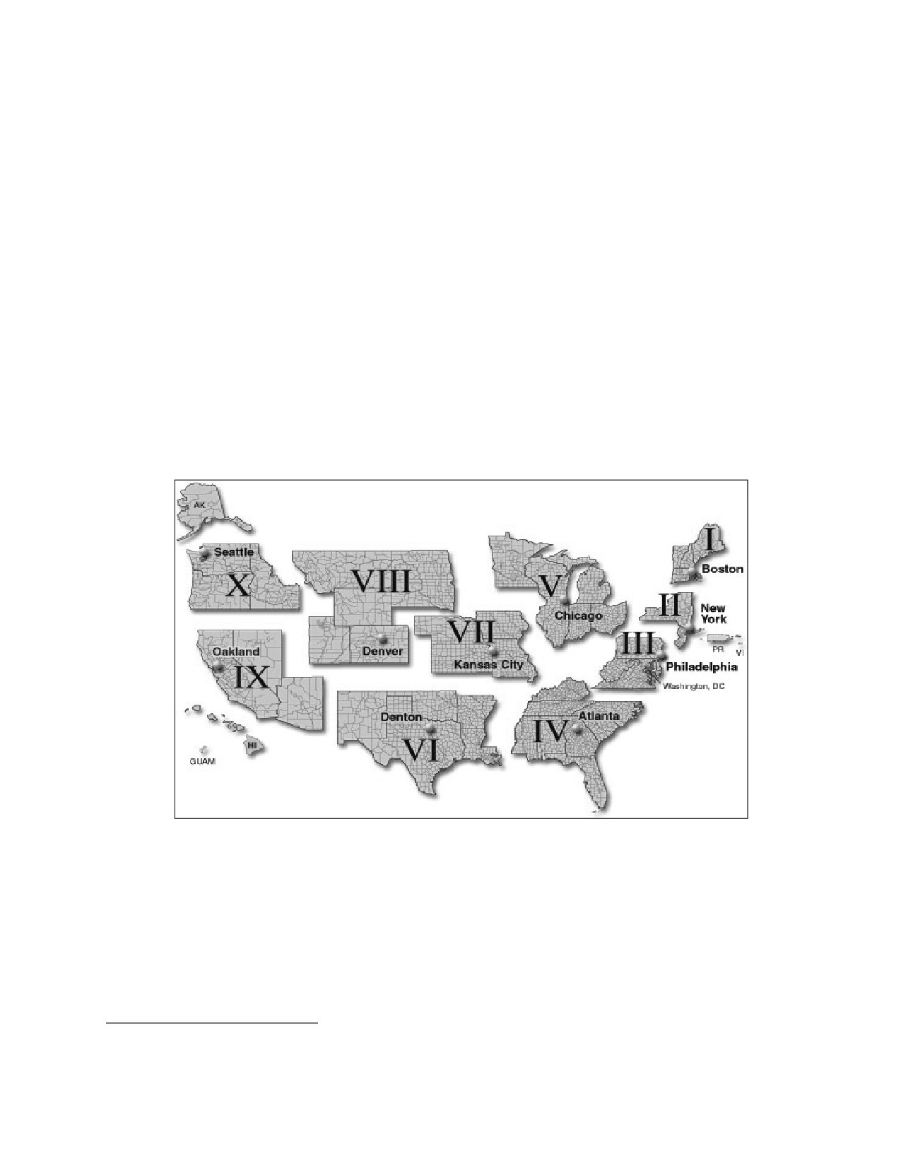
Domestic Operational Law Handbook 2011
• External Affairs Officer. The External Affairs Officer provides support to the JFO leadership in
all functions involving communications with external audiences. External Affairs includes:
Public Affairs, Community Relations, Congressional Affairs, State and Local Coordination,
Tribal Affairs, and International Affairs, when appropriate. Resources for the various External
Affairs Functions are coordinated through ESF #15. The External Affairs Officer is also
responsible for overseeing operations of the Federal Joint Information Center (JIC) established
to support the JFO.
• Defense Coordinating Officer (DCO). If appointed by DoD, the DCO serves as DoD’s single
point of contact at the JFO. With few exceptions, requests for Defense Support of Civil
Authorities (DSCA) originating at the JFO will be coordinated with and processed through the
DCO. The DCO may have a Defense Coordinating Element (DCE) consisting of a staff and
military liaison officers in order to facilitate coordination and support to activated Emergency
Support Functions (ESFs). Specific responsibilities of the DCO (subject to modification based
on the situation) include processing requirements for military support, forwarding mission
assignments to the appropriate military organizations through DoD-designated channels, and
assigning military liaisons, as appropriate, to activated ESFs. Currently, DoD has assigned
DCOs at each of the ten Department of Homeland Security/FEMA regions. (See Figure 2-1
below.)
Figure 2-1. Map of FEMA Regions with Embedded DCOs in Each Region.16
f.
Utilization of the NRF
After the President has declared a major disaster or emergency, he may direct any federal agency to
use its authorities and resources in support of state and local response efforts to the extent that
provision of the support does not conflict with other agency emergency missions. Under the
Stafford Act, FEMA serves as the lead federal agency (LFA) for disaster response and recovery
activities. The authority to direct federal agencies to use their resources in support of state and local
16 FEMA, Regional Contacts, http://www.fema.gov/about/contact/regions.shtm (last visited July 26, 2011).
Chapter 2
17
National Framework for Incident Management
Domestic Operational Law Handbook
response efforts has been delegated from the President to the Secretary of DHS.17 Under the NRF,
the President, upon the recommendation of the Secretary of DHS and the FEMA Administrator, can
appoint a Federal Coordinating Officer (FCO)18 who is responsible for coordinating the delivery of
federal assistance to the affected state(s) and local government(s) and any disaster victims. The
FCO works closely with the SCO, appointed by the governor, to oversee disaster operations for the
state. The SCO also serves as the Governor’s Authorized Representative (GAR) and is generally
empowered to execute all necessary documents for disaster assistance on behalf of the state.
5. The National Incident Management System (NIMS)
Since it was first published, NIMS has subsequently been revised to reflect input from a broad
variety of stakeholders (e.g., federal, state, tribal, local, private sector, and nongovernmental
organizations).19 In addition, lessons learned from Katrina and other recent incidents were
considered in the new version. The December 2008 revision “focused on clarifying concepts and
principles, and refines processes and terminology throughout the document . . . no major policy
changes were made to the document during the revision.”20
NIMS is comprised of five key components:
• Preparedness. NIMS focuses on the following elements of preparedness: planning; procedures
and protocols; training and exercises; personnel qualifications and certification; and, equipment
certification.21 NIMS also stresses a unified approach to management and response activities,
and that all levels of governments and organizations must identify their capabilities before
incidents occur.
• Communication and Information Management. NIMS emphasizes that well-planned,
established, and utilized communications are critical for enabling the dissemination of
information during an incident.22 Common plans, standards and communication architecture
help to facilitate interoperability and maintain a constant flow of information during an
incident.23 As with incident response in general, communication systems should be flexible and
scalable to effectively manage any situation.
• Resource Management. According to NIMS, resource management is divided into five
principles:24
• Planning;
• Use of agreements;
• Categorizing resources;
• Resource identification and ordering; and,
• Effective management of resources.
17 DEP’T OF HOMELAND SECURITY, NATIONAL RESPONSE FRAMEWORK, Jan. 2008 [hereinafter NRF].
18
Id. at 67.
19 NIMS can be viewed at http://www.fema.gov/pdf/emergency/nims/NIMS_core.pdf.
20
Id.
21
Id. at 9.
22
Id. at 23.
23
Id. at 24.
24
Id. at 32-33.
Chapter 2
National Framework for Incident Management
18
Domestic Operational Law Handbook 2011
• Command and Management. NIMS plans to incorporate the existing Incident Command
System (ICS) and Multi-Agency Coordination Systems (MACS) as the command structure for
response to all hazards at all levels of government.25 The ICS works at the tactical level,
organizing the on-scene operations.26 In comparison, MACS coordinate activities above the
field level and can be either informal or formal. Formal coordination addresses issues before an
incident occurs and is the preferred process.27
• Ongoing Management and Maintenance. HPSD-5 authorized the Secretary of Homeland
Security to establish a mechanism to ensure the ongoing management and maintenance of
NIMS. The National Integration Center (NIC) was established to assist government and private
sectors in implementing NIMS and to provide for its refinement.28 As part of this process,
NIMS notes the continued development of science and technology as playing a critical role in
improving response capabilities.
As with the Stafford Act, NIMS is based upon the premise that most incidents begin and end at the
local level, and are managed on a daily basis at the lowest level.29 There are, however, incidents
which require the involvement of higher levels of government and response.
Like the Stafford Act and its progeny, the draft NIMS is based upon the premise that most incidents
begin and end at the local level with few incidents requiring assistance from federal, state, and local
authorities.30
6. PPD-8, National Planning Replaces HSPD 8, Annex I.
President Obama promulgated PPD-8 on March 30, 2011 to replace both HSPD-8 (discussed above)
and HSPD-8, Annex I, National Planning, which was originally promulgated in 2007, to “further
enhance the preparedness of the United States by formally establishing a standard and
comprehensive approach to national planning.”31 Most notably, PPD-8 mandates:
• SECDHS, in coordination with other executive departments and agencies, must develop and
submit to the President a “National Preparedness Goal” by September 30, 2011. The
National Preparedness Goal shall be informed by the risk of specific threats and
vulnerabilities, accounting for regional variations, and shall include concrete, measurable
and prioritized objectives to mitigate risks. It must also define core capabilities necessary to
prepare for specific types of incidents that present the greatest risk to national security and
must emphasize achievement of an integrated, layered and “all-of-Nation” preparedness
approach to optimize available resources.
• SECDHS, in coordination with other executive departments and agencies, shall submit to
the President by November 30, 2011 a National Preparedness System consisting of an
25
Id. at 45.
26
Id. at 46.
27
Id. at 64.
28
Id. at 75.
29
Id. at 5.
30
Id. at 17.
31 HSPD-8, Annex I (2007) Purpose.
Chapter 2
19
National Framework for Incident Management
Domestic Operational Law Handbook
integrated set of guidance, programs, and processes that will enable the Nation to meet the
National Preparedness Goal. The National Preparedness System shall be designed to help
guide the domestic efforts of all levels of government, the private and nonprofit sectors, and
the public to build and sustain the capabilities outlined in the National Preparedness Goal.
The National Preparedness System shall include guidance for planning, organization,
equipment, training, and exercises to build and maintain domestic capabilities. It shall
provide an all-of-Nation approach for building and sustaining a cycle of preparedness
activities over time. The National Preparedness System shall include a series of integrated
national planning frameworks, covering prevention, protection, mitigation, response, and
recovery. The frameworks shall be built upon scalable, flexible, and adaptable coordinating
structures to align key roles and responsibilities to deliver the necessary capabilities.
• Individual plans developed under HSPD-8 and Annex I remain in effect until rescinded or
otherwise replaced.
HSPD-8, Annex I required the development of National Planning Scenarios.32 Consequently, the
Homeland Security Counsel developed fifteen scenarios depicting “a diverse set of high-
consequence threat scenarios of both potential terrorist attacks and natural disasters.”33
USNORTHCOM subsequently developed CONPLANs that address each of the scenarios where
DoD support is necessary. These CONPLANs can be accessed with permission of
USNORTHCOM.34
32 HSPD 8, Annex I, para. 34.
33 In 2006, the Department of Homeland Security released National Planning Scenarios, an in-depth analysis of fifteen
potential disasters that face the nation.
Scenario 1: Nuclear Detonation - 10-kiloton Improvised Nuclear Device
Scenario 2: Biological Attack - Aerosol Anthrax
Scenario 3: Biological Disease Outbreak - Pandemic Influenza
Scenario 4: Biological Attack - Plague
Scenario 5: Chemical Attack - Blister Agent
Scenario 6: Chemical Attack - Toxic Industrial Chemicals
Scenario 7: Chemical Attack - Nerve Agent
Scenario 8: Chemical Attack - Chlorine Tank Explosion
Scenario 9: Natural Disaster - Major Earthquake
Scenario 10: Natural Disaster - Major Hurricane
Scenario 11: Radiological Attack - Radiological Dispersal Devices
Scenario 12: Explosives Attack - Bombing Using Improvised Explosive Devices
Scenario 13: Biological Attack - Food Contamination
Scenario 14: Biological Attack - Foreign Animal Disease (Foot-and-Mouth Disease)
Scenario 15: Cyber Attack
See DEP’T OF HOMELAND SECURITY, NATIONAL PLANNING SCENARIOS (Apr. 2006). Two of the scenarios represent
natural disasters, major earthquake and major hurricane; a third highlights economic and social complications resulting
from a cyber attack; the remaining twelve scenarios focus on chemical, biological, radiological, nuclear, or high-yield
explosive (CBRNE) incidents.
34 USNORTHCOM CONPLANs remain in force and effect until rescinded or replaced as specified in PDD-8.
Chapter 2
National Framework for Incident Management
20
Domestic Operational Law Handbook 2011
7. Interplay between the NRF and Other Plans Applicable to WMD Response and
Recovery
When DHS initiates the response mechanisms of the NRF, including the ESFs, Support Annexes,
and Incident Annexes, the existing interagency plans that address incident management are
incorporated as supporting plans and/or operational supplements to the NRF. For incidents not led
by DHS, other federal agency response plans provide the primary federal response protocol. Other
interagency response plans include the National Emergency Communications Plan (NECP)35 and
the National Oil and Hazardous Substances Pollution Contingency Plan (NCP).36 The NRF
represents a significant effort to integrate the federal government’s inter-agency emergency and
disaster plans and may affect certain agency’s responsibilities in the event of a major disaster or
emergency.
The NECP was developed pursuant to the Homeland Security Act of 200237 to promote the ability
of emergency response providers and relevant government officials to continue to communicate in
the event of natural disasters, acts of terrorism, and other man-made disasters, and to ensure,
accelerate, and attain interoperable emergency communications nationwide.38 Emergency Support
Function 2 of the NRF supplements the NECP and sets out procedures for coordinating the
provision of temporary national security and emergency preparedness telecommunications support
in areas impacted by a major disaster or emergency.
The NCP was developed pursuant to the Comprehensive Environmental Response, Compensation,
and Liability Act of 1980 (CERCLA), as amended.39 It sets out procedures for managing oil spills
into navigable waters and releases of hazardous substances, pollutants, and contaminants into the
environment. Inland, the Environmental Protection Agency (EPA) is the lead agency for
coordinating the federal response. In coastal areas, the U.S. Coast Guard is the lead agency for
coordinating the federal response. Generally, DoD or Department of Energy (DOE) will be the lead
agency for responding to the release of hazardous substances, pollutants, or contaminants when the
incident is on or comes from a facility or vessel under the control, custody, or jurisdiction of DoD
or DOE, respectively. Finally, the EPA takes the lead for hazardous materials with respect to
incidents that have not yet been determined to be related to terrorism, or for incidents when the
NRF has not yet been activated.
Once the NRF is activated, FEMA has the lead for incident management and EPA has the lead
agency role for ESF 10, Oil and Hazardous Materials Response, incorporating the NCP. Executive
35 National Emergency Communications Plan, July 2008. It serves as a basis of planning and use of national
communications resources in support of Stafford Act provisions during a non-wartime emergency [hereinafter NECP].
36 National Oil and Hazardous Substances Pollution Contingency Plan, 40 C.F.R. 300 (2002) [hereinafter the National
Contingency Plan or NCP]. The NCP provides the organizational structure and procedures for preparing for and
responding to discharges of oil and releases of hazardous substances, pollutants, and contaminants.
37 Homeland Security Act of 2002, Pub. L. No. 107-296, 116 Stat. 2135 (2002) as amended [hereinafter Homeland
Security Act].
38 Id. at “Message from the Secretary.”
39
42 U.S.C. § 9605, as amended by the Superfund Amendments and Reauthorization Act of 1986 (SARA), Pub. L. 99-
499, [hereinafter CERCLA] and by § 311(d) of the Clean Water Act (CWA), 33 U.S.C. § 1321(d), as amended by the
Oil Pollution Act of 1990 (OPA), Pub. L. No. 101-380. Executive Orders 12580 and 12777 delegated to the EPA
responsibility to amend the NCP as necessary.
Chapter 2
21
National Framework for Incident Management