Military reference books and manuals (2009-2023, Volume 1) - page 31
FM 31-27
once if possible. When they are done drinking, make sure one of them does
not have a foot over the lead ropes as you start out. Whenever you stop on the
trail for even a short time, always be sure the pack animals are ready to go
before moving out. Often one will be spread out relieving himself and is in no
position to step out.
7-55. One of the most irritating things in leading a pack string is to have a
pack animal in the string that is always going around a tree the opposite way
the rest of the string is going. Often you can shorten the lead rope and correct
this. If that does not work you may have to lead him. This behavior is usually
a sign of a green pack animal and quite often disappears as the animal learns
what is expected of him. Others just do not ever seem to learn. If you have
one of these in your string, remember him well and leave him behind on the
next trip.
CAMPSITES
7-56. Should you have several animals in your outfit and not picket all of
them, you might find it almost impossible to keep the loose animals in the
area if there is insufficient grass. Unless you spend the entire night watching
them, they might wander off in search of good pasture and be gone in the
morning. Grass and water go together. An animal without water will act
much the same as one with insufficient grass. For this reason, every handler
should sleep with his weapon and bridle. A spring of good, sweet, cold water
is by far the best, but make sure these springs run water far enough BELOW
the camp for your stock. Another problem is that there is in most all pack or
saddle stock the tendency to want to return to the last camp, or worse yet, go
home. This urge is even more evident in them if you should be heading
towards home after a few days out on a mission.
SETTING UP CAMP
7-57. If you remember which items are in which pack you will know which
load goes where in the camp area. It will save a lot of time and labor to be
able to lead each pack animal to wherever his load goes. As soon as you get
the pack off the animal, loosen the cinches on the packsaddle.
7-58. Keeping the saddles and pads off the ground even in dry weather is a
sign of good organization. It only takes a minute to lash a pole between two
trees to put the saddles and pads on. A tree limb makes a good hanger for
lash ropes and halters. When unsaddling an animal, always keep the pad and
saddle together. If the saddle is marked for which horse it fits, you won’t have
to refit the pad next time you saddle up. If the weather is clear, let the pads
air out and dry before covering them with the mantas off the pack loads that
evening. While you are unsaddling the animals, you will need the brush and
currycomb. Ruffle the hair on the backs of the animals and check for any
tenderness or sores. If you do have a sore-backed animal, take care of it
before turning him out.
7-59. When setting up for the night, many of the items of pack gear will serve
a dual purpose. Box panniers turn into tables and stools, lash ropes turn into
high lines and corrals, mantas turn into ground tarps and covers, and so on.
7-14
FM 31-27
THE HIGH LINE
7-60. The high line is a section of rope strung between two or more trees, with
tie points for the horses. The knot used for these tie points (sometimes called
the high-line knot) can be either the pulley knot used for a single or double
dutchman, a butterfly knot, or a cat’s paw. Use the high line as a place to tie
the horses during the night.
7-61. The high line can often be temporarily put up when first arriving in
camp. It will serve as an ideal place to tie up the pack string while laying out
the camp area. Often, your lariats will serve for the first high line until you
have a lash rope off the packs. By tying up to a line when you first arrive at
camp, you often prevent damaging equipment and gear on a pack. Tying
keeps the pack animal from getting under low limbs or trying to rub the pack
off against the tree he is tied to. A very frequent mistake is tying an animal to
a small dead tree. Quite often just a light pull on the dead tree in the right
direction will cause it to fall, possibly injuring the animal or spooking him
and others into running off. In selecting the area for a high line, pick a spot
that is level and has some shelter for the animals. Shade during the daytime
will usually offer some shelter in a rainstorm.
7-62. To put up the high line, start with the lash cinch and go around an
average-sized tree approximately 7 feet off the ground. Hook the lash cinch
into the rope. If possible, run the line so another tree is approximately in the
center of the line. Tie a high-line knot approximately every 2 feet until you
come to the first tree. Go around this tree and tie high-line knots until you
get approximately 2 feet from the tree to which you intend to tie off. Use the
last knot to set up a dutchman, then go around the tree and pull the whole
line as tight as possible. Some other considerations are as follows:
• When tying to a high line, stagger the animals tied to it: one on one
side and then one on the other side.
• The high line can also make a good line to dry saddle pads when they
are not being used for the animals.
PICKETING
7-63. Picketing is tying an animal up by a line attached to either a stake or a
heavy log. It allows the animal a certain freedom of movement to walk
around and get to grass and perhaps water but does not afford him the
opportunity to wander off.
7-64. You can picket an animal in several ways. Animal handlers normally
use either a halter and picket line or a hobble and picket line off one front leg.
Depending on the animal’s experience with the picket line, picketing by a leg
is the safest. An animal picketed with a halter will sometimes hook a shoe in
the halter while scratching his ear with a hind leg. If the picketed animal
hooks the shoe of his hind leg in the picket halter he usually falls down. If not
found soon after falling, he may just die in this position.
7-65. The anchor end of the picket line can be either a good dry stake driven
into solid ground or a drag log. In selecting picket stakes, make sure they are
stout and not brittle. When placing the stakes, make sure there is plenty of
room between the stakes so two picket lines cannot cross. The drag log, when
7-15
FM 31-27
used, should be heavy enough so the animal picketed to it cannot move it, yet
light enough so, if need be, it can be pulled to another picket area using a
saddle animal and a line off the saddle horn.
7-66. In tying off a picket line to the stake, use a small bowline knot. Make
sure it is down at ground level on the stake. This level will let the line turn
around the stake and still not turn the stake and loosen it in the ground. An
animal that pulls a stake and runs loose with the line is a danger to himself
and the mission. Should the animal get into the timber and hang up the stake
and line, it could cause a day’s delay looking for him. Should the animal not
be found, it most likely will die a slow death of thirst and starvation.
7-67. Several things have to be considered when picketing by any method.
You should determine how much feed is in the picket area and if there is any
obstacle in the ring that the picket line can foul on, thus shortening the ring
area. The best area is usually on a good, grassy creek bank where the animal
can get both feed and water off the same picket line.
7-68. When selecting which animals will go on the picket line, pick out any
new animals to the outfit and any of them you know to be the leaders. Also
consider any renegades or loners who hole up by themselves when running
loose. Maybe you have a mare that has a weaner colt at home. She for certain
needs to go on a picket or on the high line. After she has had time to fill up on
grass, she just might decide to go home.
THE NIGHT HORSE
7-69. If you have some of your stock running loose during the night, a night
horse is a must. The night horse is one you keep picketed near where you
sleep for use in emergencies during the night and for running down loose
stock in the morning.
7-70. The night horse does not come in any particular color, size, or shape. He
could easily be the most inefficient looking animal in the outfit. What counts
is what is between his ears. Many an animal used as a pack animal when on
the trail, though not considered a riding horse, might make a good night
horse. The only way to come up with a top night horse is to try them all at
different times. A good night horse has to have several good points. They are
listed here, though not necessarily in order of importance:
• While on a picket, you must be able to trust the animal to graze and fill
up during the night and not just run in circles and whinny at the other
loose animals all night.
• He must handle well while running loose animals. One of the best
reining animals in the whole outfit may develop a lot of bad habits,
such as trying to buck you off, when with loose animals. Worse yet,
after you start the loose animals running, he may just stampede out of
control with you, which is a very dangerous situation.
• He should be easy to approach after dark and able to be ridden
bareback. Quite often, should the loose animals start to leave during
the night, it is possible to turn them very easily if you are right there at
the time. If the animal cannot be ridden bareback, the time it takes to
saddle up might make it too late to easily turn the loose animals.
7-16
FM 31-27
7-71. Many night horses develop the habit of watching where the loose
animals go at night. Their hearing is far superior to humans. Often, while
wrangling with a good night horse, he will want to head in a direction you
may believe is wrong. This friction can be a mistake on your part should you
not trust him to help lead you to the loose animals. Quite often a night horse
will want rein so he can smell the ground. Here again, his sense of smell is far
better than yours and he is using it to help locate the other animals.
However, do not leave everything to the horse. You most certainly will want
to be reading tracks along with using the night horse’s senses. Between the
two of you it is usually possible to locate the loose animals in short order.
7-72. The night horse is often required to do quite a bit of running in bringing
in the loose stock. This is bound to heat up the animal. Under such
conditions, cooling out the hot animal is a must. The most common mistake is
for the wrangler to tie up the hot and lathered animal and head for the cook
fire for coffee. In civilian pack outfits, many a supposedly experienced
wrangler has been discharged for this one grave mistake. The best way to cool
out a hot and lathered animal is to first unsaddle the animal. Using a
currycomb and brush, ruffle the hair over the back area. If you have some
gunnysacks available, rub him down. Above all, DO NOT grain the animal or
allow him any water until he is dry and cooled out. It could very possibly kill
the animal or at the least cause a bellyache or colic. Walking the animal will
also keep him from stiffening up. If the animal was good enough to keep on
the night horse picket, he deserves the best of care when his job is done.
7-73. A night horse should be kept on the best grass and water and as close as
possible to the area you intend to sleep. A faint nicker from where the night
horse is picketed may be the first sign you get that the other animals are
moving out. The old mountain men may have slept with their rifles, but you
should sleep with your bridle if you are the one responsible for the night
horse.
TRANSPORTING SICK AND WOUNDED PERSONNEL
7-74. Every situation varies according to what equipment you have with you
when confronted with an emergency. Look over the horses for what
equipment is on them that can be used in your situation. There are many
parts of saddles and gear strapped on them that can be pressed into service
for other than what they were intended. This section is not meant to be an
all-inclusive review of emergency procedures in the field. It is merely a brief
look at things to consider and how you can make expedient use of what you
have with you. By using your imagination and common sense and being
observant of what you have to work with, you can devise almost any type
splint, bandage, sling, stretcher, or rig slings for transportation with
equipment not necessarily intended for that purpose but which is at hand.
7-75. Bear in mind that your use of any part of the equipment may hinder
future plans to ride out for help or transport the victim. Most of the items of
equipment mentioned can be unbuckled or unsnapped rather than cut. If you
must cut off a strap, cut it close to a ring, buckle, or snap. This tip will
possibly save you hours of needless repair later.
7-17
FM 31-27
MOVEMENT
7-76. In most cases of back, neck, or any spinal injury, it is best not to
transfer the victim any great distance using horses. There is a lot to take into
consideration, such as whether the victim is on an emergency backboard and
how far it is to the nearest medical help. In most cases where the victim will
need to be transported only a short distance, a hand-held stretcher or travois
pulled by a member of the team will be faster than rigging a horse for
transportation. This way largely depends on how much help you have
available. There are several things you must NOT do when transporting a
victim with horses:
• Do not drape a wounded man head-down across a saddle.
• If the victim is inclined to pass out or is unsteady, do not let him ride
by himself. Find out if the horse will ride double by sliding behind the
saddle yourself, without the victim. If the horse will ride double, ride
behind the victim and hold him in the saddle.
• With a seriously sick or wounded victim, do not, in your haste to get to
help, trot or run the horse the victim is on. A slow, easy walk will get
the victim to assistance in better condition.
• Do not at any time leave a horse unattended with a victim strapped or
tied to the saddle. Maintain control of the horse’s head at all times.
TRAVOIS
7-77. One of the simplest and fastest means of transporting a victim who
cannot ride is a travois drawn behind one horse. This method requires getting
a gentle horse used to pulling the travois before putting the victim on one for
transportation. You can construct a stretcher with two long poles running
through the stirrups on two riding saddles that are cinched on horses. Again,
it takes the horses a little while to get used to this rigging. If you are alone
with the victim and he is conscious, place the victim’s head towards the horse
and have him hold the reins. If this is not possible, tie the bridle reins to the
poles, one on each side. This type of emergency stretcher is good for rough
country or long distance transportation. Most horses will tolerate the
stretcher between them when they have a little time to become accustomed to
the stretcher.
7-78. You can also stretch a large tarp or tent between two saddle horses that
are side by side if you have a wide trail to travel. To rig your horses for this
type of stretcher, it is wise to tie the horses’ tails together to keep them from
turning apart at the rear. A small pole tied between the bridle bits will keep
them together at the head end. Pull the tarp or tent completely over the
saddle and tie to the outside of the saddle. Two small poles, either run
through or laced to the tarp, will make a stretcher in a very short time. In
most cases it is best to have the victim’s head to the rear. Surprising as it
may seem, this type stretcher rides very comfortably.
STRETCHERS
7-79. You can use gunnysacks, canvas panniers, raincoats or saddle slickers,
pannier tarps, saddle pads, and blankets to make a stretcher. In most pack
outfits there are some gunnysacks used either to chink up a pannier or
7-18
FM 31-27
possibly to carry grain. By cutting two holes in the bottom corners of the sack
and inserting two good poles, you have a first-class wilderness stretcher.
Largely depending on what packhorses are present at the time, there is
usually a set of deep canvas panniers. These canvas panniers have several
emergency uses. You can make a stretcher with them, as with the
gunnysacks. Another very important use is for lowering or raising an
unconscious victim over such obstacles as a cliff or deep cut. You can cut two
holes the size of the victim’s legs in the bottom corners. Then slip the victim’s
legs through these two holes and pull up the fabric around his chest. Test the
knots used in tying a rope to the pannier with your weight before trusting
them on the injured victim. Raincoats, heavier coats, jackets, and saddle
slickers also make a short distance stretcher by buttoning them up the front.
Zippers are the best and most reliable. Two poles run through the inside of
the garment and out the armholes make an emergency stretcher. Pannier
tarps and large double saddle pads can make an emergency stretcher.
SPLINTS
7-80. You can use stirrup straps and fenders, pack pads, pannier tarps, pieces
of wood, box panniers, and the bars out of packsaddles to make splints. There
are many items of equipment and often items loaded on a packhorse that
make an emergency splint. You can make a backboard by taking wood box
panniers apart and either lashing or using the old nails in the box to nail or
lash the flat boards to two small dry poles. The bars out of a packsaddle
(using the flat surface) can also make a serviceable splint in a situation where
other natural materials are not available. The stirrup straps and fenders out
of a riding saddle are by far the best and simplest to obtain. You can unlace
or unbuckle them and pull them out of the saddle without damaging the
equipment. The stirrup straps and fenders from a riding saddle are already
formed to the legs, and by using both straps and fenders you can completely
immobilize the legs of a victim. These work well also for the arms by using
just one stirrup strap. Several small poles lashed flat and then padded with
pack pads can make a backboard. You can open a rifle scabbard either down
the seam or lay it flat to make a splint.
STRAPS FOR LASHING TO BACKBOARDS
7-81. Latigos, lash cinches, saddle cinches, breast collars, brichens, and bridle
reins can all be pressed into service. There are many large, heavy straps and
cinches on a pack outfit or riding saddle. You can take off almost all of these
very simply and make them serviceable for the bindings of splints or
backboards. As mentioned before, you can take off most all of these items
without cutting them and thus damaging the equipment unnecessarily.
SMALL STRAPS TO BIND BANDAGES AND SPLINTS
7-82. Bridle reins, halter ropes, sling and lash ropes, saddle stirrups, and
many of the straps on a packsaddle are useful as ties to hold things in place.
There are many such straps on packsaddles and riding saddles. Bridle reins,
for example, make a good long strap, and in an emergency that requires
continuous use of the bridle, you can get by in most instances with one bridle
rein. Almost all of the ropes, such as halter ropes and lash and sling ropes,
can be unwound and one strand taken out while still leaving the rope
7-19
FM 31-27
serviceable. If small, tight bindings are required, do not overlook tail and
mane hair from the horses you have with you. Do not make the mistake of
using your or the victim’s clothing to bind wounds and leave either of your
bodies unprotected when there are so many other items available on your
equipment. If you should consider leaving the victim and riding for
assistance, your saddle pads laid on the ground under the victim will help in
keeping him warm and dry. Often there are two pads on a horse and, in an
emergency, you could possibly get by with just one.
DIRECT PRESSURE IN SEVERE BLEEDING
7-83. Severe bleeding is always an emergency. If you should find yourself
faced with this situation and not have readily available dressings to stop the
flow of blood, a very good item on your horse is the sheepskin lining on the
underside of a saddle. A small pad of this sheepskin with a clean dressing
between it and the wound will in most instances pass for many layers of other
dressing. If you should have what is called a cool-back saddle pad, it also
makes a good emergency compress for severe bleeding.
7-20
Chapter 8
Organization and Movement
Certain combinations of adverse weather, thick vegetation, and harsh
terrain deny the use of wheeled or tracked vehicles in either a combat or
logistics role. Mountainous terrain often restricts operations to those
conducted by foot infantry. Heavily wooded areas, especially when
associated with steep grades, have the same effect. Swamps, jungle-like
vegetation, and certain types of cultivation may restrict the use of
vehicles in lowlands. Weather, in combination with unfavorable terrain,
may also deny or greatly restrict the use of aircraft in a combat or
logistics role. In such situations, the commander that can move his
troops, weapons, supplies, and equipment with the greatest speed and
facility has a distinct advantage. Properly organizing, training, and
equipping a combat pack animal detachment can give a commander this
advantage.
ORGANIZATION
8-1. The pack animal detachment is usually the smallest fighting element. It
can be a section, squad, or team of 10 to 20 individuals. The number of
animals required to support these elements depends upon both the TOE and
mission requirements.
8-2. The commander may task organize the detachment squads or sections
according to needs and requirements. For example, an 81-mm mortar section
would not need as many individuals and animals to transport the system as a
107-mm mortar section. The mission will also have an impact on the size of
the section; a raid with an 81-mm section will use fewer animals than
sustained operations would employ using the same weapons system. The
squad or section requirements may vary from as few as five animals to as
many as ten to twelve.
8-3. Other factors bearing on the organization of a pack detachment are load
weight and the size of the items to be carried. The greater the total weight of
the load, the more animals you will need to carry it. If the items are large,
even though they may be lightweight, it will take more animals.
DUTIES AND RESPONSIBILITIES
8-4. A pack animal detachment has unique duties and responsibilities. Most
of these are leadership-related and some are skills common to all.
8-5. The train commander is the commissioned officer or senior
noncommissioned officer assigned responsibility for the pack train. He
oversees the training, operation, and administration of the unit.
8-1
FM 31-27
8-6. The packmaster should be the platoon or team sergeant and the most
knowledgeable about packing. He provides for the presence, care, and
maintenance of all pack equipment and the animals in the unit. He rides the
entire column to check all loads and to observe the condition of the
individuals and animals. His specific duties include—
• Training personnel in the proper methods of packing, to include
saddling, adjusting equipment, balancing loads, and tying of standard
hitches.
• Training personnel in the proper care of animals and maintenance of
pack equipment.
• Ensuring maximum unit effectiveness through daily inspection of pack
animals for injury.
• Supervising packing, conduct of the march, maintenance of animals
and equipment, and discipline of the soldiers.
• Inspecting loads and making sure the animals on the march are not
injured by shifting loads or saddles, ensuring prompt correction of
deficiencies.
• Inspecting and directing prompt repair of packsaddlery.
8-7. The cargadores, usually squad or section leaders, assist the
packmaster in all his duties and are qualified to perform the duties of the
packmaster in his absence. In addition, cargadores must be able to make all
repairs normally made by the unit saddler. Their specific duties are to—
• Assign a load to each pack animal, ensuring the loads are balanced.
• Assign pack equipment, loads, and animals to the packers.
• Maintain order and discipline among the packers and ensure quiet and
gentle treatment of the animals.
• Select areas for cargo piles and rig line in bivouac.
• Ensure proper care of pack equipment.
• Keep a memorandum of all cargo and equipment under his care,
marking and tagging it if necessary.
8-8. The packers must train and care for both pack and riding animals. In
the field, their duties include the maintenance, adjustment, and use of pack
and riding saddlery and associated equipment. In addition, they prepare the
cargo for packing and sling and lash loads using a variety of hitches. All
detachment personnel should be packer-qualified.
MOVEMENT PROCEDURES
8-9. The pack detachment should begin movement soon after the pack
animals are loaded. Packers mount their riding animals. Two detailed riders
move ahead of the train to contain any animals that are out of control. The
detachment moves out in the march order directed by the commander in pack
strings of no more than five animals. One rider leads each string and another
follows it. You should always lead the strings from the on-side of the pack
animals (the string will be on the rider’s off-side). Normally the detachment
moves in file with the riders keeping the pack strings closed up to ensure
8-2
FM 31-27
communication between strings and to maintain column integrity. Keep in
mind, however, that terrain and probability of enemy contact from ground or
air dictates the distance between strings or squads. When moving during
hours of limited visibility, you should keep the column close to facilitate
control. Troops riding on the flanks and rear of the strings make frequent
counts of the animals to ensure against strays. Make halts as necessary to
inspect and adjust loads and saddles. The commander, packmaster, and
cargadores make frequent inspections of the detachment en route, whether
moving during daylight or at night.
STREAM CROSSING AT FORDS
8-10. Pack units will frequently come across streams or bodies of water where
no bridges exist. Although horses and mules can ford fairly deep water and
are generally good swimmers, the crossing of even fordable water requires
care and good judgment. Unit training must include accepted methods and
techniques of stream crossing. Units should conduct ford reconnaissance
before attempting to cross with a loaded pack unit. The load makes the
animal somewhat top-heavy. Try to cross streams with the animals moving
against the current (upstream). The loads in combination with swift current,
water deep enough to bear against the animal’s body, and poor footing may
cause the animal to lose its balance, fall, and drown. Under such
circumstances, you should unload the animals and either lead or herd them
across the stream. You can ferry loads across in the same manner as
described in the following paragraph.
CROSSING UNFORDABLE WATER
8-11. It is impractical to swim animals with loads and packsaddles. Though
the animal might be physically capable of swimming under the load, it upsets
the animal’s natural balance. When the pack unit must cross unfordable
water with nothing but its organic equipment, be sure to unload the pack
animals as close to the water’s edge as possible. Loosen the breeching and
secure it on top of the saddle. Also secure any loose latigo ends. You may or
may not need to unsaddle the riding animals. Selected personnel swimming
their riding animals, herd or lead the pack animals to the far shore and
secure them while others prepare a one-rope bridge and hauling system. You
should pull the equipment load by load to the far shore. If the crossing is too
wide for a one-rope bridge, you can build poncho rafts to ferry the equipment.
8-12. Operating the pack animal detachment with individually led animals is
considered uneconomical in terms of personnel. However, there are certain
circumstances under which other factors are more important. Members of the
weapons crews lead the animals that are assigned to combat units for the
transport of heavy weapons and accompanying ammunition. Animals used in
proximity to known hostile action areas are usually led individually to take
advantage of all available cover and concealment. Evacuating casualties to
aid stations by animal transport also requires this method of operation to
ensure the easiest ride for the casualty as well as to take maximum
advantage of existing cover and concealment. Although training time for this
8-3
FM 31-27
operation may be reduced, the following elements of training and operation
need to be remembered:
•
Train personnel to pack both lashed and hanger loads. Although the
animal will normally proceed at a walk, with the rate of march seldom
exceeding 3 1/2 miles per hour, make sure the loads are balanced and
securely tied.
•
Ensure the pack driver
(person leading the animal) only exerts
sufficient control over the led animal to maintain his position on the
trail or in the column. He should not interfere with the animal’s
freedom of movement or balance. A clumsy driver can cause a loaded
animal to fall.
•
Train the driver to lead the animals from the on-side. He should guide
the animal with his right hand grasping the lead rope with the
remainder of the lead rope in the left hand. He should give the animal
enough slack so that there is room enough for the animal to walk
without stepping on him. If there is noise, danger, or confusion on the
off-side, the driver may reverse his position to offer some protection to
the animal and quiet it.
•
Train personnel to regulate the speed of the animal by the gentle, but
effective, use of the lead rope. In column, always maintain the
prescribed interval to prevent accordion action and undue fatigue in
the rear elements.
•
Teach the driver to counter the tendency of the animal to trot down
slopes or jump over obstacles so he can maintain the normal rate of
march and prevent displacement of the load.
•
When leading an animal up steep slopes or over very rugged terrain,
make sure the driver precedes the animal with about 3 feet of loose
lead rope so that the animal may pick his footing. If the terrain is very
rough or steep and he falls behind, it may be best to drop the lead rope
and let the animal go. He can then catch the animal after the obstacle
is passed.
CAUTION
Under no circumstances will personnel hold the saddle
breeching or the animal’s tail to assist them in climbing.
BIVOUAC
8-13. The pack animal unit should select its camps based on the results of
both map and ground reconnaissance, if feasible. The selection depends on
the requirements for the safety, health, and comfort of individuals and
animals and the operational plans of the unit. In hostile environments,
concealment from air or ground observation and as much cover as possible
are essential. The first consideration is always security, but unless you are
packing with you all the feed the pack and saddle animals will need, the next
concern should be grass and water for the stock. It is a grave mistake to
8-4
FM 31-27
sacrifice grass, water, wood, and shelter for anything but security
considerations. In selecting the grass, make sure it is grass that the stock will
feed on all night. Just because a meadow looks green does not mean it has
plenty of grass in it; ride out and look. Often in high alpine meadows, most of
the vegetation consists of flowers and weeds that a horse will not eat. Should
you be unfortunate enough to camp in such a meadow, your stock will be
weakened from lack of grass the next day on the trail. It is very irritating to
ride or be leading an animal that insists on trying to graze as you go down
the trail. After security, your next concern should always be the care of the
animals. Reconnaissance personnel should next look for the best footing for
animals available in the area. Picket lines, high lines or, in more secure and
extended situations, temporary corrals, should offer level standing and good
drainage with little possibility of flooding in sudden rains. Make sure the
selected area is large enough to provide adequate dispersion and is free from
briers, debris, and poisonous plants. An area convenient to the route of march
offers additional operational advantages.
8-14. The detachment or train commander, accompanied by selected
personnel, precedes the train into camp and selects areas for the rigging line,
high line, and the cargo so that the animals and equipment will be arranged
systematically and readily available night or day. Upon arrival in camp, the
pack train conducts the following procedures:
• Select personnel designate the cooking and sleeping areas, keeping in
mind that they will always be located upstream from the animals.
• Upon arrival of the train, all personnel except for the “wranglers”
dismount, secure their riding animals, unload the cargo and “slack off”
cinches. Personnel unpack all animals before the first is unsaddled.
They coil the lash and sling ropes. The wranglers remain mounted and
ready to stop any animals that try to bolt from the camp.
• Personnel secure the animals as they are unloaded.
• When all loads are removed, the train commander gives the command
to unsaddle.
• If conditions are favorable, handlers turn the animals out to graze or
picket so they may roll and relax. If not, the animals stay on the high
line while personnel clean the equipment and improve the site.
• Handlers feed the animals 45 minutes after arrival and water them 1
hour after arrival. Personnel then prepare their equipment for the next
day’s movement.
8-5
Chapter 9
Tactical Considerations
A pack animal detachment during movement, regardless of its combat
mission once it reaches its destination, is a logistical transportation
element. This fact alone severely limits the detachment’s tactical
capabilities. Even though the detachment may be considered a highly
mobile unit, the presence of pack animals precludes the capability of
maneuver.
The mission of the detachment while moving is the safeguarding and
delivery of the cargo to its destination, not to stand and fight. This point
is not to say that all is lost tactically while moving; it just means that
compensation has to be made for the lack of maneuver and concentrated
fires.
SECURITY
9-1. The pack detachment configured for movement forms into pack strings
and usually in column formation. This alignment presents a long, linear
target for the enemy. The troops are dispersed, making it difficult to bring
concentrated, effective fire to bear upon enemy contact. The diligent use of
scouts and outriders for flank security, along with extreme caution, are
needed to a greater extent than for dismounted troops to make up for
maneuver limitations.
9-2. Two factors figure in not using overwatch formations. First is terrain.
The primary reason for using pack animals is difficult terrain. That
necessitates using column formations. Second, the act of bounding requires
one element to remain static. Animals that are loaded, strung together, and
not moving are an accident waiting to happen. The following paragraphs
explain how the detachment should cross specific types of areas.
9-3. Crossing at Linear Danger Areas (roads, trails, streams). When the
scouts reach a danger area, they conduct a thorough reconnaissance for the
best possible crossing point and attempt to reach the far side. Once they
establish far-side security, the scout leader returns to the column to lead it to
the crossing point. Once the column arrives at the crossing point, the lead
personnel take up far-side security and free the scouts to continue their
mission.
9-4. Crossing Open or Large Danger Areas. Commanders consider large open
areas as dangerous and their use must be negotiated accordingly. The scouts
should provide as much information about the area to the commander as
possible. With this information, the commander decides how best to negotiate
the obstacle. Bypassing the area is by far the best method but is not always
9-1
FM 31-27
practical. However, in arriving at a decision about movement, the leader
must always consider the METT-TC.
9-5. Whether during long or short halts, lead personnel establish and
maintain security using the same procedures as a dismounted combat unit.
The difference is the terrain to be defended and whether the animals will be
in or out of the perimeter. The following principles apply:
• Animals kept on a high line within the perimeter may offer a reduction
to security personnel but unique problems can arise if the position is
attacked. Casualties may arise from animals becoming frightened and
breaking loose or stampeding.
• Animals kept on picket lines outside of the perimeter require listening
posts or observation posts placed at a greater distance. During an
attack on the detachment, these animals are susceptible to both enemy
and friendly fire. The chances are good that a large percentage of the
animals will either flee or be wounded.
COVER AND CONCEALMENT
9-6. The pack detachment must continuously consider concealment options
during movement. Admittedly, it is next to impossible to conceal the evidence
(animal waste, vegetation, devastation, and tracks) that a pack unit has
moved through an area. However, you can take the following precautions to
avoid being observed while on the move.
• Avoid skylining.
• Stay well within the tree line (if any).
• Contour the terrain.
• Camouflage the loads.
• Avoid open areas, if possible, or cross them quickly.
9-7. During extended halts (when loads are unsaddled), use the proper
camouflage. Cover for the animals, while desirable, may not be possible or
practical. Remember to consider animal noise, both vocal and from
movement. Also address the odors associated with animals. There are no
clear-cut solutions to the problems of concealment. Use a common-sense
approach and practice the following tips:
• Use as much natural cover and foliage as possible.
• Use camouflage nets.
• Apply proper field sanitation techniques, to include keeping animal
waste policed.
• Control animal noise as much as possible. If the animals’ vocal cords
have not been cut, keep the animals quiet by maintaining a relaxed
atmosphere.
9-2
FM 31-27
ACTIONS ON CONTACT
9-8. As previously mentioned, a pack detachment organized for movement is
not a maneuver unit. Therefore, it must act accordingly when contact is
made.
9-9. When ambushed, those elements caught in the kill zone escape in any
feasible direction as fast as possible. Forward elements, not in the kill zone,
move in the direction of march as fast as possible. Those in the rear should
move in the direction away from the kill zone, quickly but cautiously. All
elements should make every effort to link up at a preplanned rally point.
Elements not under direct fire should make all attempts to maintain, control,
and safeguard the animals.
9-10. Actions under indirect fire are handled in much the same way as an
ambush. It may not be necessary to move to a rally point. The unit may stay
out of harm’s way until the barrage has been lifted and then continue in the
direction of march. The commander states the actions for these events and
incorporates them in the unit’s SOP before movement.
9-11. The key to surviving an air attack is dispersion and continuous
movement. The pack detachment always accounts for personnel, weapons,
and equipment after it moves to the designated rally point, establishes
security, and reestablishes the chain of command.
NOTE: Common sense, preparation, and good planning are the keys to
surviving as a pack detachment in a hostile environment.
URBAN ENVIRONMENTS
9-12. Use of any kind of animals in an urban environment requires detailed
planning and preparation. Even a clean, secure urban setting wears down the
animal and its shoes rapidly. A damaged city with extensive rubble provides
more danger in the form of sharp rock, broken glass, and other debris that
can permanently damage the animals. The best choice when planning to use
pack animals to support an urban operation is to halt them at a secure
location outside of any built-up areas and move your supplies in by foot.
However, if you must move the animals through a built-up area, be careful to
avoid rubble, broken glass, nails, and other debris that will injure the animal.
9-13. A well-equipped farrier has special shoes for pack animals if the
detachment is expected to stay in an urban environment for any period of
time. Thick rubber horseshoes work well on pavement and concrete, but do
not provide any traction on grass or any kind of dirt. Police departments
sometimes use a complex shoe with a plastic plate to protect the inner hoof, a
steel shoe over that, and carbide bits welded to the shoe. The carbide bits
provide traction on asphalt and concrete, the shoe itself provides traction off
road and the plastic protects the horse’s inner hoof from nails, glass, and
other debris.
9-14. Normally the pack animal detachment will not have access to any
special equipment to protect the animals. As mentioned earlier in this
manual, shoes wear out much quicker on rocky or rough terrain. This is even
more apparent when operating in any kind of urban environment. The
9-3
FM 31-27
detachment must check the animals’ feet for any damage constantly
throughout the day and must pay close attention to the animals during
movement to watch for any injuries as soon as they occur. Routes must be
selected and checked ahead of time to reduce the danger to the animals as
they move. Special care must be taken to avoid any rubble, concrete, or
asphalt along the route.
9-4
Chapter 10
Llamas and Other Animals
Although this manual focuses on horses and mules, this chapter provides
basic information about other types of pack animals that a team may
encounter. With the exception of llamas, these animals will normally
come with a native handler that should be considered the primary source
of information for the use of that animal.
LLAMAS
10-1. Llamas are members of the camel (camelid) family. In addition to the
well known, one-humped dromedary camel of the Middle East and the two-
humped Bactrian camel of Asia, there are four native members of the camel
family in the Americas today: the llama, a domesticated beast of burden
regarded throughout the world as the premier symbol of South American
animals; the alpaca; the free-ranging guanaco; and the wild vicuna.
CHARACTERISTICS
10-2. While viewed in the pasture or close contact, all llamas have a striking
beauty owing to their elegant wool and graceful posture. Llama wool ranges
from white to black, with shades of gray, brown, red, and roan in between.
Markings can be in a variety of patterns from solid to spotted. Little variation
is found in guanacos or vicunas, which are light brown with white undersides.
10-3. Mature llamas weigh an average of 280 to 350 pounds, but range from
250 to 500 pounds. Full body size is reached by the fourth year and, while
there are no obvious differences between the sexes, males tend to be slightly
larger. They are long-lived, with a normal life span of 15 to 20 years.
10-4. Like cattle and sheep, llamas are multistomached and chew the cud.
They have a hard upper gum (no upper teeth in front), grinding upper and
lower molars in back, and a cleverly designed upper lip for grasping forage in
unison with the lower incisors. Adult males develop large, sharp upper and
lower canines (“wolf teeth” or “fangs”) for fighting. You should ask your
veterinarian to remove these to prevent injury to males pastured together or
to females being bred.
10-5. The llamas’ unique, specially adapted foot makes them remarkably
surefooted on a variety of terrain, including sandy soils and snow. It is two-
toed with a broad, leathery pad on the bottom and curved nails in front. The
small, oblong, bare patches on the side of each rear leg are not vestigial toes
(“chestnuts” as found on horses), but metatarsal scent glands, suspected to be
associated with the production of alarm pheromones. An additional scent
gland is located between the toes.
10-1
FM 31-27
HOUSING AND FENCING
10-6. Fencing can be woven wire, cattle wire panels, wooden rails or poles,
chain link, or electric. Barbed wire is not recommended. Your fences should
be at least 4 feet high and dog proof if possible.
10-7. The llamas should have a three-sided shelter to provide shade and
protection from extreme heat, cold, wind, and rain. If the area has severe chill
factors in winter, a completely enclosed shed is necessary. Heat stress should
be a concern if there are hot and especially humid summers. You may want to
consider shearing or clipping your llama for this type of weather. If you do
not intend to shear your stock, then a sprinkler, wading pool, or small pond
may be helpful in keeping your llamas cool for the summer.
10-8. If your animals are kept in a large pasture, a small 12- to 20-foot square
catch pen will make it easier to catch them. Feeding and watering troughs
should be clean, high enough to be free of possible fecal contamination, and
spacious enough to allow access by all animals. You should always ensure
that fresh water is available.
TRANSPORTATION
10-9. Llamas are easy to transport and require no specialized equipment. A
covered, windproof pickup, van, and horse or utility trailer with sufficient
room for animals to stand comfortably works well. Good ventilation is
important in both summer and winter. Straw makes excellent bedding in a
windproof enclosure. Be sure to provide hay for food and offer water free-
choice at least every 6 hours depending on heat (it will spoil if left with the
animals). Llamas normally lie down (kush) once the vehicle starts moving.
When transporting babies and mothers on long hauls, stop periodically to
allow nursing.
CARE AND FEEDING
10-10. If you are familiar with the care of other domestic livestock, you will
find llamas comparatively easy to care for, with a minimum of veterinary
assistance required. If you are uncertain of the health of your new animal,
consider isolating it in sight of but separate from your others for the first 2
weeks to prevent accidental introduction of any illnesses and to give you both
a chance to get acquainted. Make sure it is eating and ruminating, and
eliminating pelleted feces.
10-11. If you have not already done so, locate a veterinarian in your area. If
he is inexperienced with llamas, information and assistance is available
through various animal clinics in Canada and the United States. It is
recommended that you have your veterinarian give your newcomer a general
health check and take a fecal sample to determine if worming is necessary.
10-12. Llamas are amazingly hardy animals and have very few problems
with disease. But to ensure good health, you should establish a regular
schedule for cleaning their dung piles and a preventative medicine program
that may include protection from enterotoxemia, tetanus, leptospirosis, and
internal and external parasites. Llamas should be dewormed at least every 6
months. Be sure to check with your veterinarian or agricultural extension
agent to see if any vital trace elements or minerals are deficient or present in
10-2
FM 31-27
toxic amounts in your area. Consult your veterinarian for other preventative
medicine suggestions or to see if any special circumstances (meningeal worm,
selenium levels, toxic plants) are problems in your area.
10-13. Although llamas have long been arid land dwellers, they thrive in the
wide array of temperate environments throughout Canada and the United
States, including Alaska. They are highly adaptable feeders, being both
grazers (grasses and forbs) and browsers (shrubs and trees).
10-14. Because of a relatively low protein requirement due to their efficient
digestive systems, they can be kept on a variety of pastures or hay. They eat
about 2 to 4 percent of their body weight in dry matter each day. Without
pasture, a 100-pound bale of hay will last an adult llama around 10 days,
much longer than the same amount would last an adult horse. If you’re going
to graze your llamas, plan on about three to five animals per acre on a
moderate-producing pasture.
10-15. When good hay is available, grain is recommended only for working
pack animals and nursing females. Sheep mineral blocks and salt blocks
(with selenium wherever necessary) should be available free-choice.
Granulated minerals are somewhat more wasteful than mineral blocks, but
are easier to eat. High-protein grain mixes prepared for other livestock
should generally not be given to a healthy llama on a good diet, unless it’s a
female nursing or close to giving birth. Llamas are not prone to bloat, but
have been known to do so if they get into a grain bin.
10-16. Llamas require less water than most domestic animals, but should
have an unlimited, fresh, clean supply at all times. They tend to drink less in
winter and when on lush, green pasture and more when working or lactating,
especially in summer.
10-17. Unless your llamas are pastured on hard or rocky ground, you may
have to trim their toenails once or twice a year. It’s easy to do yourself with
horse hoof trimmers or sheep toenail nippers, but consult your veterinarian
before your first attempt.
HABITS AND BEHAVIOR
10-18. Llamas have a dignified, aristocratic manner about them. Because of
their curiosity, they have a delightful habit of coming close to sniff strangers.
But despite your natural temptation to hug and cuddle them, they prefer not
to be petted except on their necks and woolly backs. They are gentle, don’t
spook easily, and rarely bite or kick unless provoked. They are highly social
animals and need the companionship of other llamas.
10-19. Llamas communicate their moods with vocalizations and a series of
tail, body, and ear postures. Learning this llama language is one of the joys of
ownership. Humming is a common manner of communication between llamas
and indicates a variety of moods from contentedness to concern. Another
interesting llama expression is the shrill, rhythmic alarm call emitted at the
sight of a strange animal (especially coyotes and dogs) or a frightening
situation.
10-20. Seldom directed at people, spitting is usually related to food disputes
and to establish a pecking order between llamas. The exception to this is if a
10-3
FM 31-27
llama has been mishandled or become imprinted on people (through bottle-
feeding as a baby). As with bottle-fed stallions, bulls, and rams, bottle-fed
male llamas who have not been gelded at an early age can be potentially
dangerous as adults (because they lack a normal fear of people and regard
them as competitors). Therefore, males not intended for breeding and males
that were bottle-fed must be gelded as early as possible to avoid undesirable
behavior.
10-21. Llamas are remarkably clean and even large herds are quite odorless.
Dung-piling behavior is an important means of spacial orientation and
territorial marking for these historically open habitat animals—a
convenience when you clean their pens. By taking advantage of this habit,
you can encourage your animals to establish dung piles in a new pen by
“probating” four to five sites per acre with a shovelful of llama dung. You may
frequently see your llama rolling in the dirt, taking a dust bath to help
maintain a healthy, fluffy coat of wool.
USES AND TRAINING
10-22.
“What are they used for?” is a question commonly asked of llama
owners. The domesticated llama in South America is used for low fat meat,
wool, hide, manure (for fertilizer and fuel), and as a beast of burden. This
multipurpose animal lends itself well to the needs of the South American
people. The llama in North America is used for investment, breeding, wool
production, packing, tourism, sheep guards, shows, competitions, and as a
source of diversification.
10-23. Llama wool production is a multimillion dollar industry in South
America and makes llamas appealing to spinners and weavers here. Llamas
have soft, fine wool for insulation against cold and heat. The llama’s wool can
also be harvested yearly by clipping or shearing and be made into beautiful
garments and blankets. The yearly wool harvest produces 3 to 8 pounds of
grease-free fleece with a fiber length of 4 to 7 inches. Year-round brushing
yields about the same results and leaves the long, coarser guard hairs in
place.
10-24. The llama’s centuries-old ability as a beast of burden has been
rediscovered by hikers, hunters, and forest work crews. The llamas’
hardiness, surefootedness, and common sense make them an excellent pack
animal, trail companion, and even a great golf caddy. They are quiet,
unobtrusive, and so easy to manage that children love to lead them. Their
great agility allows them to negotiate terrain that would be difficult or
impossible for traditional pack animals. Because of their padded feet and
ability to browse, they have minimal impact on the backcountry. When
confronted by other pack stock, unexpected situations, and sudden movement
or noises, llamas remain calm and unruffled.
10-25. Males are most commonly used for packing and, depending on
maturity, weight, and condition, will tote 50- to 120-pound packs 10 to 15
miles a day. A variety of packs and halters are available for llama use.
10-26. Because they are gentle and easy to train, llamas are popular
attractions in parades, shows, fairs, and community events, and are fun to
take to school, hospital, or nursing home visits.
10-4
FM 31-27
10-27. Llamas are fast becoming the choice for protecting sheep flocks from
predators such as stray dogs and coyotes. They are also good competitors.
Conformation is judged at llama shows to determine the best of each halter
class. The llama’s training and disposition are judged in performance
competitions such as obstacle and driving classes.
10-28. Surprisingly, there is a market for llama manure. It is high in
nitrogen, basically odorless, weed-free, and easily collected. It is a valuable
plant and garden fertilizer.
10-29. Their docile nature makes llamas extremely easy to train to accept a
halter, lead, kush, carry a pack, load in and out of a vehicle, pull a cart, or
carry a lightweight rider. With just a few repetitions, they will pick up and
retain any of these skills. Llamas with minimum training are easy to handle
when you are trimming nails, brushing or shearing, or when health problems
necessitate touching them in sensitive places.
DOGS
10-30. The use of dogs as an auxiliary in war is as old as war itself. Primitive
man used dogs to guard his family, his belongings, and himself. He also took
his dog into battle with him when rival tribes clashed. Throughout the history
of warfare, dogs have gone into combat at the side of their masters or have
been used in direct support of combat operations.
10-31. Dogs have long been recognized by the military as important for war
and security purposes. The Army has employed various dog breeds and has
determined the German shepherd to be the most suitable for scouting
because of its working ability, temperament, size, availability for
procurement, and adaptability to all types of climate and terrain. These dogs
are especially good at detecting ambushes. While “reading” the dog, the
handler must prevent him from barking, growling, whining, or otherwise
making a noise, which would be audible to a lurking enemy. Such a reaction
on the dog’s part might be fatal to both dog and handler in combat.
10-32. Next the dog is urged to move silently through built-up areas. After
learning the basic rules, the dog is then trained to detect an enemy decoy
planted farther and farther away. Lessons are repeated under varied
conditions at different times of the day and night until the animal becomes
expert enough to detect an enemy at distances up to 500 yards or more.
10-33. Dogs have many uses in combat and were valued especially by the
infantryman. Taken with patrols into no-man’s-land, their keen senses
reduce the chance of fatal surprise or ambush by giving silent warning of a
concealed enemy. During the hours of darkness or when visibility is poor,
dogs can guard command or observation posts against enemy infiltration, a
problem that was acute in Korea and Vietnam.
10-34. After he develops a strong fondness for two or more handlers, the dog
is taught to run from one to the other. One handler releases the dog and
commands the animal to “report.” As soon as the dog reaches the second
handler he receives warm praise. Just before the dog runs, his “choke” chain
is removed and a “messenger” collar is put on. Soon he learns to associate this
collar with his job of running from one man to the other. As the lessons
10-5
FM 31-27
proceed, the distance between the men is increased beyond the range of the
dog’s vision. He now learns to trail his masters by scent. Frequent repetition
and runs of varied distances over different kinds of terrain finally develop his
dependability as a messenger.
10-35. In training, the dog customarily carries a pack, which can be loaded
with supplies or ammunition. He also learns to lay field telephone wire from
a spool mounted on a specially constructed pulling harness. Before being
graduated as fully trained, he must be able to follow a scent up to distances of
5 miles. He must be able to carry up to 30 pounds of ammunition and supplies
over rough terrain. He must also demonstrate his capability in carrying and
stringing a 1-mile spool of telephone wire between two points. Using dogs as
pack animals has advantages and disadvantages.
10-36. The advantages of using a dog are that he—
• Has intelligence, making him a tool that can be used for tactical
advantage.
• Has keen senses of sight, smell, and hearing.
• Can trail handlers by scent over great distances.
• Can sleep anywhere the handlers sleep.
• Can eat the same food as his handlers.
• Can carry packs up to 35 pounds.
• Can perform various duties; for example, string communications wire
and carry messages.
• Shows early warning against possible enemy, mines, or boobytraps.
• Requires short periods of time to recover.
• Adapts well to changes in climate.
10-37. The disadvantages of using a dog are that he—
• Is a 24-hour-a-day responsibility of the soldier.
• Adds additional stress to the handler by being an additional
responsibility.
• Needs proper equipment to operate continuously in summer, winter,
and in rugged terrain.
• Can have his performance adversely affected by extreme temperatures.
• Can be rendered completely ineffective by pad injuries.
• Needs additional food and water.
• Can be adversely affected by noxious odors.
CAMELS
10-38. There are two basic types of camels: Arabian (short fur, one hump)
and Bactrian (long fur, two humps). Arabians can carry packs weighing 200
to 300 kg for a distance of 30 to 35 km. Bactrians can carry a load of 150 kg
for 7 to 8 hours for a distance of 25 to 35 km. Camels can also pull loads of
1,650 pounds or 3,300 pounds by two, per day at normal walking speed.
10-6
FM 31-27
10-39. Camels have broad, flat, leathery pads with two toes on each foot.
When the camel places its foot on the ground, the pads spread, preventing the
foot from sinking into the sand. When walking, the camel moves both feet on
one side of its body, then both feet on the other. This gait suggests the rolling
motion of a boat, explaining the camel’s “ship of the desert” nickname. They
need very little water and can travel for days without drinking at all. Camels
are clumsy-looking, rather ugly animals, and have a lousy reputation because
they are believed to spit and kick at people. This perception is not accurate
because well-handled camels are safe to work with and be around.
10-40. As stated above, camels will come with native handlers to take care of
them. The handler should be considered the detachment’s first choice when
planning operations using a camel.
ELEPHANTS
10-41. Elephants are considered an endangered species and as such should
not be used by U.S. military personnel. There are about 600,000 African
elephants and between 30,000 and 50,000 Asian elephants. Approximately 20
percent are in captivity so it is difficult to estimate their numbers exactly.
The Convention of International Trade in Endangered Species regards both
species as threatened. Elephants are not the easygoing, kind, loving creatures
that people believe them to be. They are, of course, not evil either. They
simply follow their biological pattern, shaped by evolution. The secret of
becoming a good trainer is to learn this pattern. You can then apply it on
yourself and the elephants under your control.
10-7
Glossary
ALICE
all-purpose, lightweight individual carrying equipment
ARSOF
Army special operations forces
auger
Any of various tools or devices used for boring holes or moving
loose material.
BCS
body condition score
btl
bottle
cm
centimeter(s)
CNS
central nervous system
cross tie
A mild form of restraint in which the animal’s head is secured in
a normal raised position by two tie ropes extending from the ring
in the halter to opposite sides of the stall or between two trees.
ea
each
EIA
equine infectious anemia
F
Fahrenheit
farrier
A person who shoes horses.
FM
field manual
forb
A broad-leaved herbaceous plant, as distinguished from the
grasses, sedges, shrubs, and trees.
gal
gallon
general support
Support that is given to the supported force as a whole and not to
any particular subdivision thereof. (FM 101-5-1)
GRAIL
Soviet SA-7 surface-to-air missile
hackamore
A bridle with a loop capable of being tightened about the nose in
place of a bit or with a slip noose passed over the lower jaw.
harborage
A place of shelter or lodging.
HEENT
head, ears, eyes, nose, and throat
hr(s)
hour(s)
I&D
incise and drain
IM
intramuscular
ISBN
International Standard Book Number
IU
immunizing unit
IV
intravenous
Glossary-1
FM 31-27
kg
kilogram(s)
km
kilometer(s)
LAW
light antitank weapon
lb
pound(s)
LCE
load-carrying equipment
manta
A piece of canvas, from 7 by 7 feet up to 10 by 12 feet, used to
throw over the load as a cover to protect it.
METT-TC
mission, enemy, terrain, troops, time available, and civilians
mg
milligram(s)
military operations
Military activities during peace and conflict that do not necessarily
other than war
involve armed clashes between two organized forces.
NSN
national stock number
operational continuum
The general states of peace, conflict, and war within which
various types of military operations are conducted.
pannier
A large container or basket often carried on the back of an
animal.
pcn G
penicillin G
pkg
package
po
by way of mouth
pr
pair
pt
pint
q
every
running “W”
A type of restraint where both front legs are restricted by rope
and can be pulled out from under the horse. Should only be done
on soft ground to prevent injuring the horse’s knees.
SAW
squad automatic weapon
SO
special operations
SOP
standing operating procedures
TOE
table of organization and equipment
TOW
tube-launched, optically tracked, wire-guided missile
travois
A simple vehicle, drawn behind one horse, that consists of two
trailing poles serving as shafts and bearing a platform or net for
the load or person.
twitch
A loop of rope or chain that is tightened over a horse’s lip as a
restraining device.
U.S.
United States
Glossary-2
FM 31-27
USAJFKSWCS United States Army John F. Kennedy Special Warfare Center
and School
UW unconventional warfare
VEE Venezuelan Equine Encephalomyelitis
withers The ridge between the shoulder bones of a horse.
yds yards
Glossary-3
Bibliography
AR 40-905. Veterinary Health Services, August 1994.
FM 21-76. Survival, June 1992.
FM 25-5. Training for Mobilization and War, January 1985.
FM 41-10. Civil Affairs Operations, January 1993.
FM 55-15. Transportation Reference Data, October 1997.
FM 100-1. The Army, June 1994.
FM 100-20. Military Operations in Low Intensity Conflict, December 1990.
Animal Management, London: His Majesty’s Stationary Office, 1923.
Animal Management, London: His Majesty’s Stationary Office, 1933.
Back, Joe. Horses, Hitches, and Rocky Trails. Boulder: Johnson Books, 1959.
Brelis, Dean, and Peers, William R. Behind the Burma Road. Atlantic-Little, Brown and
Company, 1963.
Cavalry Combat, The Cavalry School, U.S. Army, Norristown: Telegraph Press, 1937.
Daly, H.W. Manual of Pack Transportation. 1917.
Davis, Francis. Horse Packing in Pictures. New York: Charles Scribner’s Sons, 1975.
de Romaszkan, Gregor. Fundamentals of Riding,. New York: Knuph, 1982.
Encyclopedia Americana, No. 17, Chicago: Encyclopedia Americana, Inc., 1963.
Encyclopedia Britannica, No. 22 and No. 8. New York: Encyclopedia Britannica, Inc., 1963.
Green, LTC. The Guerrilla and How to Fight Him, New York: Frederick and Praeger, Inc.,
1962.
History for 1943 Veterinary Service in North Africa and Mediterranean Theater of
Operations, USAMEDS Historical Unit, Office of Surgeon General, Washington, D.C.
Lewis, Lon D. Care and Feeding of the Horse. 2d Ed. Williams and Wilkins, 1996.
Manual of Horsemanship, Equitation and Animal Transport, London: His Majesty’s
Stationary Office, 1937.
Nelson, Bud. Skills of Packing and Shoeing. Vol. 2, Jackson Hole, WY, 1975.
Nutrient Requirements of Horses, 5th Ed. National Academy Press, Washington, DC: 1989.
Bibliography-1
FM 31-27
Osanka, Franklin March, Editor. Modern Guerrilla Warfare, New York: The Macmillan
Company, 1962.
Parrino, Michael F. Pack Transport and Pack Artillery. New York: The Queensland
Publishing Company, 1956.
Randolph, John. Marsmen in Burma. Houston: Gulf Publishing Company, 1946.
Twelveponies, Mary. There Are No Problem Horses, Only Problem Riders. Boston, MA:
Houghton Mifflin, 1982.
United States Army in World War II, China-Burma-India Theater Stilwell’s Command
Problems, Office of the Chief of Military History, Department of the Army, Washington,
DC, 1956.
U.S. Fifth Army History, 7 October to 15 November, Part II, AVolturno to the Winter Line.
Army, “A Bray for the Army Mule,” CPT Gaspard, George L., USA, March 1964: 70.
Army, “Where the Troops Are,” LTC Rathburn, Frank F., March 1964: 39.
The Army Times, “No Plans for Those Mules, Long Ear Type,” 25 March 1964: 3.
The Marine Corps Gazette, “Guerrilla Warfare in China,” Griffith, James B., June 1951: 20.
The New York Times, “Mules in India,” New York: 7 June 1964.
Animal Management Transportation, USAJFKSWCS, Fort Bragg, NC: May 1964.
Drivers Horse Transport, HQ RASC Training Centre, Malaysia: January 1964.
Employment of Pack Animals, Basic School, Marine Corps School, Quantico, VA: November
1961.
Officers Animal Transport Course, HQ RASC Training Centre, Malaysia: April 1963.
Special Operations Animal Packing Course (SOAP-C), 2nd Battalion, 5th Special Forces
Group, Fort Campbell, KY, 42223-5000, June 1996.
Bibliography-2
Index
A
first aid
movement procedures, 8-2
through 8-4
animal conformation, 2-1 through
supplies, 4-6, 4-7
2-4
treatment, 4-7 through 4-15
N
night horse, 7-16, 7-17
B
G
bridle, 6-1, 6-2
grooming, 3-1 through 3-3
P
packsaddles, 5-1, 5-2
C
H
pack string, 7-11 through 7-14
camels, 10-7,
halter, 5-3, 5-4
pharmacological listing, 4-17
cinching, 5-9, 5-10
harness, parts of, 5-6
picketing, 7-15
combat considerations
high line, 7-15
weapons, 6-10, 6-11
hobbles, 2-5, 2-6
R
equipment, 6-12
rations, types of
cover and concealment, 9-2
I
garrison, 2-13
immunization, 4-16
field, 2-13
D
emergency, 2-13
detachment personnel, 8-1, 8-2
K
restraints, 3-11 through 3-14
dogs, 10-5, 10-6
knots, 7-1 through 7-3
riding techniques, 6-6 through 6-8
E
L
S
elephants, 10-7
llamas, 10-1 through 10-5
saddle, fitting of, 5-6 through 5-8
euthanasia, 4-17, 4-18
security, 9-1
M
slings and hitches, 7-7 through
F
7-11
medical supply list, 4-16
farrier tools, 3-4, 3-5
mission, enemy, terrain, troops,
time available, and civilians
U
feeding, 2-9 through 2-13
(METT-TC), 1-1, 6-11
urban environments, 9-3
Index-1
FM 31-27
By Order of the Secretary of the Army:
ERIC K. SHINSEKI
General, United States Army
Chief of Staff
Official:
JOEL B. HUDSON
Administrative Assistant to the
Secretary of the Army
DISTRIBUTION:
Active Army, Army National Guard, and U.S. Army Reserve: To be distributed in accordance
with initial distribution number ?????, requirements for FM 31-27.
TM 3-11.42
MCWP 3-38.1
NTTP 3-11.36
AFTTP 3-2.83
MULTI-SERVICE TACTICS, TECHNIQUES,
AND PROCEDURES FOR
INSTALLATION EMERGENCY MANAGEMENT
June 2014
DISTRIBUTION RESTRICTION: Distribution authorized to U.S. government agencies and their contractors only
due to the sensitive nature of information contained in the manual. This determination was made on 1 July 2012.
Other requests for this document must be referred to one of the Service proponents listed in the preface.
DESTRUCTION NOTICE: Destroy by any method that will prevent disclosure of contents or reconstruction of the
document.
HEADQUARTERS, DEPARTMENT OF THE ARMY
FOREWORD
This publication has been prepared under our direction for use by our respective commands and other
commands as appropriate.
VANCE P. VISSER
RICHARD P. MILLS
Colonel, USA
Lieutenant General, USMC
Commandant
Deputy Commandant for
U.S. Army Chemical, Biological,
Combat Development and Integration
Radiological, and Nuclear School
T.B. KRAFT
DAVID L. REYNOLDS
Rear Admiral, USN
Colonel, USAF
Commander
Commander
Navy Warfare Development Command
Headquarters Air Force Civil
Doctrine Center
Engineer Support Agency
This publication is available at Army Knowledge Online
(https://armypubs.us.army.mil/doctrine/index.html). To receive publishing
updates, please subscribe at
U.S. Navy Web sites at <https://ndls.nwdc.navy.mil> and
<https://ndls.nwdc.navy.smil.mil>, the U.S. Air Force Web site at
https://www.doctrine.usmc.mil/.
Marine Corps PCN: 143 000078 00
*TM 3-11.42
MCWP 3-38.1
NTTP 3-11.36
AFTTP 3-2.83
Technical Manual
U.S. Army Training and Doctrine Command
Fort Monroe, Virginia
No. 3-11.42
Marine Corps Warfighting Publication
Marine Corps Combat Development Command
Quantico, Virginia
No. 3-38.1
Navy Tactics, Techniques, and Procedures
Navy Warfare Development Command
Norfolk, Virginia
3-11.36
Air Force Tactics, Techniques, and Procedures
Headquarters Air Force Civil Engineer Support Agency
Tyndall Air Force Base, Florida
3-2.82
23 June 2014
Multi-Service Tactics, Techniques, and
Procedures
for
Installation Emergency Management
Contents
Page
PREFACE
iv
INTRODUCTION
vi
Chapter 1
FUNDAMENTALS OF INSTALLATION EMERGENCY MANAGEMENT
1-1
National Structure for Incident Management
1-1
Terms of Reference
1-3
Framework
1-4
Operating Environment
1-5
Tasks and Responsibilities
1-7
Summary
1-10
Chapter 2
PREPARE
2-1
Actions
2-1
DISTRIBUTION RESTRICTION: Distribution authorized to U.S. government agencies and their contractors only
due to the sensitive nature of information contained in the manual. This determination was made on 1 July 2012.
Other requests for this document must be referred to one of the Service proponents listed in the preface.
DESTRUCTION NOTICE: Destroy by any method that will prevent disclosure of contents or reconstruction of the
document.
*This publication supersedes ATP 3-11.42, dated 26 April 2013.
23 June 2014
TM 3-11.42/MCWP 3-38.1/NTTP 3-11.36/AFTTP 3-2.83
i
Contents
Installation Emergency Management Program
2-2
Risk Management
2-5
Installation Emergency Management Plan
2-6
Support for Coordinating Programs
2-7
Civilian Coordination and Interoperability
2-10
Individual and Family Preparedness and Community Awareness
2-11
Training, Exercises, and Evaluation
2-12
Summary
2-14
Chapter 3
RESPOND
3-1
Actions
3-1
Command and Control
3-3
Integration of Support Activities
3-7
Communications
3-7
Resource Management
3-10
Summary
3-12
Chapter 4
RECOVER
4-1
Actions
4-1
Recovery Management
4-2
Sustainment and Restoration of Infrastructure and Operations
4-4
Mass Care
4-5
Debris Clearance and Environmental Remediation
4-5
Resource Management
4-6
Mortuary Affairs
4-6
Public Health
4-7
Summary
4-7
Chapter 5
MITIGATE
5-1
Actions
5-1
Vulnerability Reduction
5-2
Mitigation Planning
5-4
Lessons Learned
5-5
Summary
5-6
Appendix A
METRIC CONVERSION CHART
A-1
Appendix B
RISK MANAGEMENT
B-1
Appendix C
INSTALLATION EMERGENCY MANAGEMENT PLAN
C-1
Appendix D
RESPONSE OPERATIONS AND EMERGENCY OPERATIONS CENTERS .. D-1
Appendix E
COMMUNICATIONS
E-1
Appendix F
RESOURCE MANAGEMENT
F-1
Appendix G
SUPPORT AGREEMENTS
G-1
Appendix H
EVACUATION, SHELTER IN PLACE, AND LOCKDOWN
H-1
Appendix I
MASS CARE OPERATIONS
I-1
GLOSSARY
Glossary-1
REFERENCES
References-1
INDEX
Index-1
ii
TM 3-11.42/MCWP 3-38.1/NTTP 3-11.36/AFTTP 3-2.83
23 June 2014
Contents
Figures
Figure 1-1. The four phases of IEM
1-4
Figure 2-1. Prepare phase
2-1
Figure 3-1. Respond phase
3-1
Figure 3-2. ICS interface
3-4
Figure 4-1. Recover phase
4-1
Figure 5-1. Mitigate phase
5-1
Figure B-1. Risk assessment process
B-1
Figure B-2. USMC threat hazard matrix template (notional data)
B-7
Figure B-3. USAF risk assessment and mitigation matrixes (notional data)
B-8
Figure G-1. Sample MAA/MOU template
G-1
Tables
Table 2-1. Prepare phase functions and actions
2-2
Table 3-1. Respond phase functions and actions
3-2
Table 4-1. Recover phase functions and actions
4-2
Table 4-2. Recommended composition of the recovery working group
4-3
Table 5-1. Mitigate phase functions and actions
5-2
Table 5-2. Potential hazard mitigation controls and techniques
5-3
Table A-1. Metric conversion chart
A-1
Table B-1. U.S.N. relative risk evaluation matrix (notional data)
B-6
Table B-2. USAF risk assessment work sheet (notional data)
B-9
Table C-1. Examples of ESF responsibilities and manager roles
C-5
Table C-2. Examples of EM plan section content
C-15
23 June 2014
TM 3-11.42/MCWP 3-38.1/NTTP 3-11.36/AFTTP 3-2.83
iii
Preface
Multi-Service Tactics, Techniques, and Procedures for Installation Emergency represents a significant
renaming and revision to the November 2007 publication Multiservice Tactics, Techniques, and Procedures for
Installation CBRN Defense. It expands the scope from chemical, biological, radiological, and nuclear (CBRN)
defense to all-hazards installation emergency management (IEM), including the management of CBRN events.
This publication defines the roles of Department of Defense (DOD) installation commanders and staffs and
provides the tactics, techniques, and procedures (TTP) associated with installation planning and preparedness
for response to, and recovery from, hazards to save lives, protect property, and sustain mission readiness. The
purpose of this publication is to summarize existing policies, responsibilities, and procedures for IEM programs
at DOD installations worldwide for all hazards, as defined by DODI 6055.17, and to translate this policy into
tactical terms applicable to military installation commanders. The contents have been written to complement
Service IEM program manuals, standard operating procedures (SOPs), response standards, training support
packages, collective task training development products, training center and unit exercises, and Service school
curricula related to IEM.
The principal audience for Multi-Service Tactics, Techniques, and Procedures for Installation Emergency
Management is military installation commanders, functional and Service component staffs, emergency
managers, nonemergency management personnel performing collateral or additional emergency management
(EM) duties, and civil service and contract EM personnel with application to the joint force command and joint
task force that are tasked with the planning, preparation, and execution of EM. Trainers and educators
throughout DOD will also use this manual.
Commanders, staffs, and subordinates ensure their decisions and actions comply with applicable United States
(U.S.), international, and, in some cases, host nation (HN) laws and regulations. Commanders at all levels
ensure their Soldiers operate in accordance with the law of war and the rules of engagement (see FM 27-10).
Multi-Service Tactics, Techniques, and Procedures for Installation Emergency implements STANAGs 2047
(Edition 7), STANAG 2521 (Edition 1), STANAG 2873 (Edition 4), and STANAG 4359 (Edition 1).
Multi-Service Tactics, Techniques, and Procedures for Installation Emergency uses joint terms where
applicable. Selected joint and Army terms and definitions appear in both the glossary and the text. Terms for
which Multi-Service Tactics, Techniques, and Procedures for Installation Emergency is the proponent (the
authority) are marked with an asterisk (*) in the glossary. For definitions shown in the text, the term is
italicized, and the number of the proponent follows the definition. This publication is not the proponent for any
new terms.
Multi-Service Tactics, Techniques, and Procedures for Installation Emergency applies to installation
populations in their entirety, including active and reserve component military personnel unless otherwise stated;
DOD civilians; military families; installation tenants; transient military or U.S. government personnel;
contractor personnel; visitors and guests; HN personnel; third country national personnel; and other relevant
populations in the surrounding community outside of the installation.
The proponent of this publication is the U.S. Army CBRN School, who developed this publication with the joint
participation of the approving Service commands. We encourage recommended changes for improving this
publication. Please reference changes by specific page and paragraph, and provide a rationale for each
recommendation. Send comments and recommendations directly to—
iv
TM 3-11.42/MCWP 3-38.1/NTTP 3-11.36/AFTTP 3-2.83
23 June 2014
Preface
Army.
Commandant
U.S. Army CBRN School
ATTN: ATZT-TDD-C
14001 MSCoE Loop, Suite 2617
Fort Leonard Wood, Missouri 65473
Commercial (573) 563-7364
Web site: <http://www.wood.army.mil/cbrns>
Marine Corps.
Deputy Commandant for Combat Development and Integration
ATTN: MCCDC CDD MID DCB C116
3300 Russell Road, Suite 204
Quantico, Virginia 22134-5021
Defense Switching Network (DSN) 278-6233; Commercial (703) 784-6233
Web site: <https://www.doctrine.usmc.mil/>
Navy.
Commander
Navy Warfare Development Command
ATTN: N5
1528 Piersey St, Building O-27
Norfolk, Virginia 23511-2699
DSN 341-4203; Commerical (757) 341-4203
Web site: <https://ndls.nwdc.navy.mil/>
Air Force.
Headquarters Air Force Civil Engineer Support Agency
ATTN: CEXR
139 Barnes Drive, Suite 1
Tyndall Air Force Base, Florida 32403-5319
DSN 523-6169; Commercial (850) 283-6169
Web site: <www.e-publishing.af.mil>
Appendix A contains a metric conversion chart for this manual. A complete listing of preferred metric units for
general use is contained in Federal Standard 376B.
Unless this publication states otherwise, masculine nouns and pronouns do not refer exclusively to men.
23 June 2014
TM 3-11.42/MCWP 3-38.1/NTTP 3-11.36/AFTTP 3-2.83
v
Introduction
Multi-Service Tactics, Techniques, and Procedures for Installation Emergency discusses the principles of
EM as they apply to military installations. This publication provides doctrine TTP for planning,
preparedness, execution, and continuous assessment in each of the four phases of EM. During military
operations, this publication is subordinate to current (joint publications [JPs] that address related topics,
such as chemical, biological, radiological, and nuclear consequence management (CM) and defense support
of civil authorities (DSCA). It covers all-hazards and coordinating operations, such as emergency support
functions (ESFs) or functional areas.
The IEM involves the complex coordination of planning and response efforts with the installation
command and staff; tenant command staff; and local, state, federal, and HN civilian authorities. Tenant and
transient installation units also actively contribute resources to IEM mutual assistance plans. Installation
commands strive to become familiar with the local community outside the installation that will impact EM
operations. They are also knowledgeable of the relationship of their operations to federal guidelines
governing civilian EM at national, state, and local levels.
This document addresses the various roles of the installation command for each phase of an EM life cycle.
The primary overlapping phases in an EM life cycle are—
z
Preparing for installation emergencies.
z
Responding to installation emergencies.
z
Recovering from installation emergencies.
z
Mitigating installation emergencies.
Preparations for an installation emergency are directed toward planning, interoperability, and intelligence.
Preparedness activities increase the resilience of the installation community and the response and recovery
capabilities of the installation through risk management; coordination; task organization; equipment,
training, and certification; exercise; and readiness evaluation.
Response operations include the actions taken from the initial notification of a potential or actual incident
until the transition to the recovery phase begins. Immediate response measures following an installation
emergency include the notification of the affected populace within 10 minutes and the execution of the
Incident Command System (ICS) by installation first responders. The emergency may also require the
activation of emergency operations centers (EOCs). Response roles could extend beyond installation
boundaries. Civil authority support and joint reception, staging, onward movement, and integration
(JRSOI) functions also occur during the response phase. Most response functions are conducted using the
ICS and are supported through ESFs or equivalent organizational structures (such as functional areas)
within the EOC.
The installation commander executes recovery operations within his own available organic and
precoordinated resources. Recovery activities emphasize immediate response and mitigation measures to
protect critical infrastructure and restore critical functions to their preincident capability. Short-term
recovery actions seek to restore essential services and ensure that the needs of the installation community
are met. Long-term recovery actions include restoring operations, rebuilding destroyed property, and
reconstituting military operations and services. The main goal of recovery is mission reconstitution and the
restoration of essential operations. The final steps of a recovery operation include capturing lessons learned
and the subsequent required revisions of the EM plan upon reassessment. The National Disaster Recovery
Framework (NDRF) was published in 2001, replacing the National Response Framework (NRF), ESF-14,
Long-Term Community Recovery. The NDRF expands key ESF-14 concepts into a full framework.
Mitigation actions involve the lasting (and often permanent) reduction of, exposure to, probability of, or
potential loss from identified hazards. The goal of mitigation is to reduce the impact of identified hazards
on critical/essential operations, critical assets, critical infrastructure, essential services, assigned personnel,
and government and personal property. Mitigation is an ongoing process that feeds directly into the overall
preparedness of the installation. Mitigation can be accomplished through the implementation of sustainable
development activities, vulnerability reduction measures, and hazard prevention efforts consistent with
command guidance through the vulnerability assessment (VA) process.
vi
TM 3-11.42/MCWP 3-38.1/NTTP 3-11.36/AFTTP 3-2.83
23 June 2014
Introduction
While the installation EM plan covers the usual activities associated with preparing for, responding to,
recovering from, and mitigating the effects of an incident, the installation command and EM staffs also
coordinate EM activities with various supporting entities established on and off the installation. Plans for
the coordination and execution of ESFs or functional areas, continuity of operations (COOP), and critical
infrastructure protection (CIP) are aligned with the installation EM plan to ensure the appropriate allocation
of resources and manpower in all sectors of emergency response.
The goal of this multi-Service publication is to revise the November 2007 edition of Multiservice Tactics,
Techniques, and Procedures for Installation CBRN Defense to expand the scope from CBRN to all-hazards
EM for individuals on, or assigned to, a DOD installation. Accordingly, this publication is renamed Multi-
Service Tactics, Techniques, and Procedures for Installation Emergency Management. The decision to
revise the multi-Service TTP resulted from—
z
The publication of DODI 6055.17.
z
The results of the Joint Requirements Office-led, front-end analysis that identified doctrinal gaps in
the passive defense and weapons of mass destruction CM capabilities-based assessments.
z
The request for feedback results received from the Services.
Note. This publication is now aligned with DOD and federal civilian EM principles, policies,
and guidance for all-hazards incidents.
23 June 2014
TM 3-11.42/MCWP 3-38.1/NTTP 3-11.36/AFTTP 3-2.83
vii
This page intentionally left blank.
Chapter 1
Fundamentals of Installation Emergency Management
This chapter establishes the environment for installation EM. It provides the terms of
reference and framework for IEM—prepare for, respond to, recover from, and
mitigate the effects of an incident. It discusses the interface between military doctrine
and federal guidance, such as the National Incident Management System (NIMS), the
ICS, the NRF, and the National Preparedness Goal (NPG). It also presents an
overview of the anticipated tasks and responsibilities of installation command and
staff in the construction and proliferation of an IEM program. These fundamental
principles guide the preparation for, and implementation of, the IEM program
discussed in following chapters.
NATIONAL STRUCTURE FOR INCIDENT MANAGEMENT
1-1. Consistent with DODI 6055.17 and HSPD 5, IEM plans for domestic installations are developed in
compliance with NIMS, ICS, NRF, and NPG procedures. Also consistent with DODI 6055.17, installations
outside the United States implement NRF and NIMS principles as much as possible when executing IEM
programs.
1-2. The national structure for incident management establishes a clear progression of coordination and
communication from the local level to regional and national headquarters levels. Specific elements of this
governing structure are detailed in the following sections.
NATIONAL INCIDENT MANAGEMENT SYSTEM
1-3. For military installations, the use of NIMS supports the interoperability between installations, other
Services, and the civilian community. All DOD components maintain interoperability with the ICS.
1-4. The following are NIMS components:
z
Preparedness.
z
Communications and information management.
z
Resource management.
z
Command and management, including the ICS.
z
Ongoing management and maintenance and supporting technologies.
1-5. The NIMS process supports the following:
z
Integrating incident-related prevention, mitigation, response, and recovery activities.
z
Improving coordination and integration within the military operational area and with federal,
state, local private-sector, and nongovernmental organization (NGO) partners.
z
Increasing the efficient use of resources needed for more effective incident management.
z
Improving situational awareness (SA) within the installation.
z
Providing timely and accurate information for public awareness.
z
Facilitating requests for assistance (RFAs) that exceed the installation response capability.
z
Providing linkage to technical reachback capabilities.
23 June 2014
TM 3-11.42/MCWP 3-38.1/NTTP 3-11.36/AFTTP 3-2.83
1-1
Chapter 1
INCIDENT COMMAND SYSTEM
1-6. The ICS is a flexible, standardized, on-scene, all-hazards incident management approach. It is
executed and prioritized according to the principles of life safety, incident stabilization, and property
conservation.
1-7. The ICS enables the coordination and integration of personnel, facilities, procedures,
communications, and equipment among various jurisdictions and functional agencies. It also establishes a
common process for planning and managing resources.
NATIONAL RESPONSE FRAMEWORK
1-8. The NRF is an all-discipline, all-hazards framework for the management of incidents. Consistent
with DODI 6055.17 and HSPD 5, the DOD implements policy and procedures concordant with the roles
and authorities under the NRF.
1-9. The purpose of the NRF is to establish a comprehensive, national, all-hazards approach to incident
management; therefore, the elements of an installation response plan are consistent with the roles and
authorities under the NRF.
1-10. The following are the key principles of NRF doctrine:
z
Engaged partnerships.
z
Tiered responses.
z
Scalable, flexible, and adaptable operational capabilities.
z
Unity of effort through unified command (UC).
z
Readiness to act.
NATIONAL PREPAREDNESS GOAL
1-11. PPD 8 sets a strategic vision for national preparedness by using a comprehensive approach to
preparedness. It also requires the development and maintenance of the NPG.
1-12. The NPG defines the core capabilities necessary to prepare for the incidents that pose the greatest
risk to national security. The NPG establishes concrete, measurable, prioritized objectives to mitigate
specific threats and vulnerabilities—including regional variations of risk—and emphasizes actions intended
to achieve an integrated, layered, accessible, and all-of-nation/whole community preparedness approach
while optimizing the use of available resources.
MISSION ANALYSIS
1-13. The overarching objective of a comprehensive, all-hazards IEM program is to maintain DOD
operational readiness throughout, and subsequent to, disasters or emergencies on or near DOD installations
worldwide. Consistent with DODI 6055.17, the goals of the DOD IEM program are to—
z
Prepare DOD installations for emergencies.
z
Respond appropriately to protect personnel, save lives, and protect property.
z
Recover and restore operations after an emergency.
1-14. It is also DOD policy that IEM programs—
z
Maintain DOD readiness by establishing and maintaining a comprehensive, all-hazards IEM
program on DOD installations worldwide.
z
Support and assist U.S. civil authorities, as directed, in EM activities.
z
Coordinate preparedness, response, and recovery requirements and capabilities with state, local,
and tribal governments; other military departments; or HN partners by using an all-hazards
approach that balances risk management (threat, vulnerability, consequence), resources, and
need.
z
Align with federal guidance, which is outlined in the NIMS, ICS, and NRF and is consistent
with HSPD 5.
1-2
TM 3-11.42/MCWP 3-38.1/NTTP 3-11.36/AFTTP 3-2.83
23 June 2014
Fundamentals of Installation Emergency Management
STRATEGIC TO TACTICAL
1-15. IEM planning involves strategic, operational, and tactical level plans. Strategic planning usually
occurs at the higher echelon levels, and individual IEM plans develop operational and tactical level plans
that support and adhere to the strategic guidance from higher headquarters.
z
Strategic. At this level, decisionmakers determine broad objectives and develop high-level
guidance for the IEM program. Lower-level plans developed by IEM personnel adhere to this
guidance and accomplish these objectives.
z
Operational. Operational objectives support strategic objectives, sequence events, initiate
actions, and apply resources to begin and sustain activities. Operational planning is also
conducted and sustained across the IEM program range of operations
(prevent, respond,
recover). Plans written at this level are more narrowly scoped and more detailed than strategic
plans.
z
Tactical. Tactical planning is more focused and detailed than operational planning. Activities
are focused on the arrangement of resources in relation to each other and to a specific threat or
hazard. Tactical plans are developed to support the objectives of operational plans.
z
Services. Each of the Services has developed IEM programs based on unique Service
requirements and existing DOD doctrine. While many aspects of the Service programs are
similar, there are select differences that will be addressed by exception when necessary.
TERMS OF REFERENCE
1-16. The following terms of reference and complementary doctrine apply throughout this document:
z
All hazards. All hazards are any incident, natural or manmade, including those defined in DODI
6055.07, that warrants action to protect the life, property, health, and safety of military members,
dependents, and civilians at risk, and minimize any disruptions of installation operations (DODI
6055.07).
z
CBRN consequence management. CBRN CM is the response activities that require resource
allocation beyond CBRN passive-defense capabilities for all deliberate and inadvertent release
of CBRN hazard(s).
z
Consequence management. CM is the actions taken to maintain or restore essential services
and manage and mitigate problems resulting from disasters and catastrophes, including natural,
manmade, or terrorist incidents. It is a military-unique function that is coordinated with EM. (JP
3-28)
z
Emergency management. EM is the coordination and integration of all activities necessary to
build, sustain, and improve the capability to prepare for, protect against, respond to, recover
from, or mitigate against threatened or actual natural disasters, acts of terrorism, or other
manmade disasters (NRF).
z
Emergency management alignment with chemical, biological, radiological, and nuclear
defense activities. EM is not a military-unique function and is complementary to CBRN defense
activities. IEM plans are developed in coordination with CBRN defense plans, including the
recognition of potentially overlapping capabilities and resources. IEM capabilities and functions
are not exempt from applicable Occupational Safety and Health Administration
(OSHA)
standards, the National Institute for Occupational Safety and Health guidelines, or the guidelines
of other applicable federal agencies. Additional information can be found in Multiservice
Tactics, Techniques, and Procedures for Chemical, Biological, Radiological, and Nuclear
Consequence Management Operations.
z
Geographic locations. U.S. military installations support operational forces in domestic and
foreign environments. The installation location is critical in determining the laws and regulations
that must be applied and in establishing the level of military authority that the installation
commander may have in determining response actions, including the level of personal protection
for the response force.
Domestic locations. Domestic locations are the continental United States, Alaska, Hawaii,
the Commonwealth of Puerto Rico, the U.S. Virgin Islands, the U.S. territories of Guam,
23 June 2014
TM 3-11.42/MCWP 3-38.1/NTTP 3-11.36/AFTTP 3-2.83
1-3

Chapter 1
American Samoa, Jarvis Island, the Commonwealth of the Northern Marianas Islands, the
Freely Associated States of Micronesia, the Republic of Palau, the Republic of the Marshall
Islands, and the U.S. possessions of Wake Island, Midway Island, Johnson Island, Baker
Island, Howland Island, Palmyra Atoll, and Kingman Reef (DODI 2000.21).
Foreign locations. Foreign locations are any geographic area not reflected in the definition
of domestic (DODI 2000.21).
z
Installations. Installation is a base, camp, post, station, yard, center, or other activity under the
jurisdiction of the secretary of a military department or, in the case of an activity in a foreign
country, under the operational control of the secretary of a military department or the Secretary
of Defense. The term installation does not include leased facilities. (DODI 6055.17)
FRAMEWORK
1-17. Chapters 2 through 5 describe the phases of IEM that can occur sequentially or simultaneously
before, during, or after an emergency incident (see figure 1-1). The following are the phases of IEM:
z
Prepare.
z
Respond.
z
Recover.
z
Mitigate.
Figure 1-1. The four phases of IEM
PREPARE
1-18. The installation EM plan drives preparation efforts and facilitates response and recovery operations.
Preparation and planning are based on an assessment of the operating environment. Operational
assessments enable commanders and emergency managers to identify the minimum standards for training,
organizing, equipping, and protecting resources. The implementation and approval of the EM plan (and
related agreements) increase readiness through training and exercises. Chapter 2 discusses the preparation
phase in more detail.
1-19. Because of the breadth and scope of disasters that a comprehensive program must cover, IEM plans
and programs are detailed and flexible. An IEM program will gain strength and substance through
coordination with installation tenants and with local, state, federal, tribal, territorial, and HN authorities.
1-4
TM 3-11.42/MCWP 3-38.1/NTTP 3-11.36/AFTTP 3-2.83
23 June 2014
Fundamentals of Installation Emergency Management
RESPOND
1-20. Actions taken during this phase address the short-term, direct effects of an incident. Response
measures include those actions taken to save lives, protect property, and continue essential services and
operations. Chapter 3 discusses the response phase in more detail.
RECOVER
1-21. The focus of recovery activities is the restoration of mission capability and the essential public and
government services interrupted by the incident. The recovery phase also includes completing the
mitigation of the immediate hazard. Chapter 4 discusses the recovery phase in more detail.
MITIGATE
1-22. Sustainable development and vulnerability reduction measures are initiated during the mitigation
phase in support of hazard prevention and suppression of known hazards. Chapter
5 discusses the
mitigation phase in more detail.
1-23. IEM programs are comprehensive and address all hazards that the installation may experience,
including natural and manmade incidents. These events may be intentional or accidental, foreseen or
unpredictable. Employing an all-hazards approach encourages interoperability; enables the effective use of
resources; and protects critical operations, personnel, assets, and the environment during likely emergency
events.
OPERATING ENVIRONMENT
1-24. IEM planning accounts for every relevant component of the operating environment on an installation.
These components include threat considerations; geographic frameworks; political, military, economic, and
social infrastructures; information systems; geographically remote locations; physical environments; and
the technological facts detailed below.
THREAT
1-25. There are common threat considerations that apply to military installations across the range of
military operations, ranging from stable peace to general war conditions. Installations receive intelligence
summaries that provide information on local or regional threats. Threats and hazards can range from
adversarial actions, to manmade incidents, to natural disasters. Threat and hazard assessments are
coordinated with similar assessments created by state and local civilian authorities. These authorities often
have specific intelligence regarding natural hazard threats, such as information on hurricane susceptibility
that would be useful in the preparation of a threat assessment for the installation. (See appendix B for
additional information on threat and hazard assessments.)
GEOGRAPHIC FRAMEWORK
1-26. The IEM plan accounts for the entire assigned operational area and the associated areas of interest.
The operational area controls response actions and establishes boundaries within which the installation
commander operates. The area of interest represents the environment external to the operational area for
which the installation commander must maintain SA and may include surrounding communities and civil
authorities with whom the installation commander establishes agreements for coordinated notification,
response, and recovery operations.
POLITICAL SYSTEMS
1-27. The political environment often impacts decisions to develop, approve, and honor support
agreements between jurisdictions, especially in large-scale emergencies with the potential to impact the
populace of another jurisdiction. Military authority, jurisdictional authority, and established agreements are
among the important political and legal considerations for the installation commander.
23 June 2014
TM 3-11.42/MCWP 3-38.1/NTTP 3-11.36/AFTTP 3-2.83
1-5
Chapter 1
MILITARY SYSTEMS
1-28. Regardless of the scope or nature of an incident, military systems function under the appropriate
designated military chain of command. Military units supporting an emergency on an installation or in
support of a civil jurisdiction are always under the command of military authorities, even though these
forces may provide support to civil authorities as directed under DODD 3025.18.
ECONOMIC SYSTEMS
1-29. Installation commands operate within the usual economic system parameters in terms of
appropriations for supplies and other resource requirements during the preparation and mitigation phases.
During the response and recovery phases, emergency cost account codes are developed to track and
manage response and recovery costs for submission to higher headquarters for supplemental funding
requests and for reimbursement based on local support agreements.
SOCIAL SYSTEMS
1-30. Installation commanders consider cultural, ethnic, and religious attitudes and behaviors that may
impact operations. Installations have varying degrees of social environments confined within a small
jurisdictional area. These environments range from long-term residents in family housing to short-term
student populations, and from large, special-event crowds from local civil jurisdictions to cohesive
combatant units stationed on post or transiting the installation for training and exercises. The social
environment usually extends into local civil jurisdictions, with potentially large components of the military
community residing outside the jurisdictional boundaries of the installation commander. The social
environment often includes foreign nationals, including multinational partners and third-country nationals
with varying social norms. The important political, legal, and cultural issues that the installation
commander must address include—
z
Jurisdictional authority.
z
Established agreements and contracts.
z
Continuous media interaction.
z
Local customs.
INFRASTRUCTURE SYSTEMS
1-31. Infrastructure systems determine specific requirements for transportation, utilities, communication,
preparedness elements (evacuation and mutual aid timelines), and specific material requirements for
response and recovery actions. Additional mitigation and prevention requirements may be required to
ensure the protection and robustness of critical infrastructure.
INFORMATION SYSTEMS
1-32. The installation commander strives to achieve enhanced SA and understanding through
interoperability with other military and civil authorities. The installation commander determines the sources
of information (including intelligence) and the appropriate stakeholders for information sharing. Certain
incidents may require notification procedures among military commanders and civil authorities. These
notification procedures are based on common agreements and preestablished methods.
GEOGRAPHICALLY REMOTE LOCATIONS
1-33. Installations may be further defined by their location relative to local civil jurisdictions and
supporting resource providers. Remote installation defines an installation that, due to its remote location in
relation to other U.S. or HN response assets, may require additional capabilities to adequately respond to,
and recover from, an emergency.
1-6
TM 3-11.42/MCWP 3-38.1/NTTP 3-11.36/AFTTP 3-2.83
23 June 2014
Fundamentals of Installation Emergency Management
PHYSICAL ENVIRONMENT
1-34. Key components of the physical environment include the effects of terrain and weather, the
geographic framework that influences the installation commander’s plan, and the installation commander’s
ability to exercise authority. Physical conditions drive mitigation and prevention requirements and
determine the specific requirements for response and recovery operations in terms of area-specific
organizing, training, equipping, and exercising personnel.
TECHNOLOGICAL FACTORS
1-35. The technological infrastructure and operations present on and around the jurisdiction directly impact
the IEM program across all phases. These technological conditions may include the—
z
Transit, storage, manufacture, or use of hazardous materials (HAZMAT).
z
Ignition sources for available fuel loads.
z
Potential for aviation, maritime, or land transport accidents.
z
Increased reliance on cyber and electronic systems for daily operations.
z
Distributed financial management and distribution systems.
z
Additional sources of environmental pollution or contamination.
1-36. These technological factors may indicate the presence of specific technological hazards (structural
collapse, transportation accidents, HAZMAT release). Technological conditions may determine specific
requirements for transportation and mobility, including evacuation, mutual aid timelines, and specific
material requirements such as structural-collapse rescue capabilities.
TASKS AND RESPONSIBILITIES
1-37. The tasks and responsibilities identified in paragraphs 1-43 through 1-45 are assigned to designated
leaders and leadership groups to ensure the creation, maintenance, and proliferation of a functional,
comprehensive, and integrated all-hazards EM program on each military installation worldwide.
Note. For a checklist of additional and coordinating responsibilities, see the Initial Operational
Capability Checklist and the Full Operational Capability Checklist found in DODI 6055.17.
INSTALLATION COMMANDERS
1-38. Within the DOD, installation commander is defined as the individual responsible for all operations
performed by an installation. For the purposes of this publication, it is further defined as the commander at
the lowest local level, excluding regional-level commanders, who may assume control of an installation
during the course of an emergency.
1-39. All installation commanders (including those located in domestic and foreign environments) are
required to—
z
Establish an IEM program that is—
Comprehensive for all hazards.
Coordinated with appropriate military and civilian authorities.
Integrated with the overall protection mission for the installation.
z
Designate, in writing, an installation emergency manager with the responsibility for overall
program coordination and integration with other response elements of the installation (or as
coordinated with external sources) according to DODI 3020.52 and DODI 6055.17.
z
Ensure that the installation emergency manager and staff develop a comprehensive, all-hazards
IEM plan and that the plan is trained, rehearsed, and exercised.
z
Direct installation activities and allocate resources to support the IEM program and plan.
z
Create, in concert with the installation emergency manager, an installation emergency
management working group (IEMWG) to provide recommendations to the command on how to
improve the planning, training, and exercising of the IEM program.
23 June 2014
TM 3-11.42/MCWP 3-38.1/NTTP 3-11.36/AFTTP 3-2.83
1-7
Chapter 1
z
Designate and establish an installation EOC.
z
Direct inspections and assessments of IEM readiness and preparedness.
z
Create, maintain, and execute applicable inter-Service support agreements
(ISSAs),
memorandums of understanding (MOUs), memorandums of agreement (MOAs), and mutual aid
agreements (MAAs) with tenant units or local civilian jurisdictions to provide mutual aid.
z
Review memorandums annually.
z
Appoint, in writing, a public health emergency officer (PHEO) based on the guidance set forth in
DODI 6200.03 to provide public health and medical advice to the command during a public
health emergency.
z
Ensure that tenant organizations participate in the IEM planning process, are included in the
IEM plan, and participate in the requisite EM training and exercises on the installation.
z
Ensure that tenant organization EM plans, checklists, and operating instructions implement the
execution tasks outlined in the IEM plan.
z
Ensure the health, well-being, and safety of the entire installation populace through the
integration and enforcement of appropriate public health and safety actions during an emergency
event, consistent with relevant OSHA safety standards and health service support guidelines.
INSTALLATION COMMANDERS IN FOREIGN OPERATING ENVIRONMENTS
1-40. In addition to the requirements listed above, installation commanders located in foreign operating
environments must also—
z
Integrate installation and HN emergency response capabilities to support the sustainment of
installation capabilities and readiness according to status-of-forces agreements (SOFAs).
z
Coordinate IEM measures with respective area or base cluster commanders.
z
Identify interoperability requirements and mitigation measures to help meet emergency response
requirements.
z
Monitor or support negotiations and/or implement MOUs and/or MOAs with HNs as necessary.
z
Support HN EM and response assistance.
z
Coordinate training opportunities with supporting HN resources to periodically exercise existing
MOUs and/or MOAs.
z
Review and approve exercise scenarios for exercises that are consistent with the regional threat
assessment.
z
Receive briefings on SOFAs and other international agreements affecting HN emergency
response capabilities appropriate to the installation.
INSTALLATION EMERGENCY MANAGER
1-41. The installation emergency manager, designated by the installation commander, has overall lead
responsibility for the integration and synchronization of installation all-hazards planning and response
activities. The installation emergency manager—
z
Develops and maintains the comprehensive, all-hazards IEM plan; supporting annexes;
associated instructions; SOPs; and checklists.
z
Collaborates and coordinates with installation responders; state, local, and tribal governments;
other military departments; and HN emergency managers to achieve the highest possible level of
IEM plan integration and interoperability.
z
Ensures that critical infrastructure, threat/hazard, vulnerability, consequence, and response
capability assessments are integrated into the IEM plan.
z
Coordinates with the PHEO and medical treatment facility (MTF) emergency manager to ensure
that medical resource management activities are coordinated and included in the IEM plan.
z
Coordinates with installation responders; tenants; local, state, tribal, and territorial governments;
and HN agency emergency managers to ensure that EM plans are mutually supporting and are
properly integrated.
1-8
TM 3-11.42/MCWP 3-38.1/NTTP 3-11.36/AFTTP 3-2.83
23 June 2014
Fundamentals of Installation Emergency Management
z
Employs resource management activities to coordinate the prioritization and allocation of
installation resources.
z
Integrates installation emergency response requirements into resource planning.
z
Ensures that installation emergency response teams and personnel training occur across the
range of installation operations.
z
Periodically assesses installation emergency response capabilities.
z
Ensures that community awareness is incorporated into emergency planning, preparation, and
training.
z
Provides subject matter expertise to support communication regarding installation-specific, all-
hazards planning.
z
Serves as program coordinator for the IEMWG.
Note. The Air Force uses a medical EM representative to meet the MTF EM requirements of
DODI 6200.03.
INSTALLATION EMERGENCY MANAGEMENT WORKING GROUP
1-42. Consistent with DODI 6055.17, the installation commander establishes an IEMWG (see chapter 2 for
additional information regarding the IEMWG). The IEMWG performs the following functions:
z
Develops and maintains the community profile.
z
Executes the IEM program implementation plan.
z
Conducts the continual risk management process.
z
Develops and maintains the IEM plan.
z
Coordinates the development of emergency action plans (EAPs) by tenant commands as directed
by the IEM plan.
z
Coordinates the implementation of preparedness phase activities according to the IEM plan.
z
Coordinates and supports installation community preparedness.
z
Coordinates NIMS implementation.
z
Supports NIMS resource management activities.
z
Coordinates with and supports installation continuity programs.
z
Coordinates the development of command, control, and communications capabilities according
to the IEM plan.
z
Coordinates the development of evacuation management and mass care capabilities.
z
Coordinates preincident recovery planning and preparations, including facility surveys for use in
damage assessment activities.
z
Reviews training and certification reports for compliance with plan requirements.
z
Reviews exercise and evaluation reports for compliance with plan requirements.
z
Reviews after action reports (AARs), improvement plans (IPs), and corrective-action plans
(CAPs) to identify plan deficiencies and make applicable updates on an annual basis or as
required.
z
Coordinates the implementation and completion of CAPs.
z
Supports installation status reporting, including EM-related service areas.
z
Collects, validates, and prioritizes budget and financial requirements for submission into the
program objective memorandum process.
TENANT AND TRANSIENT UNITS
1-43. Tenant and transient unit commands, located on military installations worldwide, perform the
following functions:
23 June 2014
TM 3-11.42/MCWP 3-38.1/NTTP 3-11.36/AFTTP 3-2.83
1-9
Chapter 1
z
Reports the EM status and capabilities to the installation emergency manager upon arrival at the
installation and updates that status annually. The installation emergency manager includes these
capabilities into the IEM plan as appropriate.
z
Provides the applicable staffing, resources, and training to support coordinated and sustained
operations.
z
Coordinates installation responder and tenant EM plans, checklists, and operating instructions
with the IEM plan; and ensures that installation responder and tenant IEM plans integrate
assumptions and resources between them.
z
Participates in IEM training and exercises as requested by the installation commander.
z
Participates in IEMWG.
SUMMARY
1-44. In the United States, EM is structured according to the guiding national principles found in the NRF,
NIMS, NPG, and ICS. All IEM plans and activities comply with this guidance. This instruction
promulgates a comprehensive, all-hazards EM framework that is organized into the following four
integrated phases: prepare, respond, recover, and mitigate. In the planning and execution of an IEM
program, installation commanders consider the unique factors of their own operating environment.
Installation staffs are cognizant of their roles and responsibilities in the creation and implementation of an
IEM program.
1-10
TM 3-11.42/MCWP 3-38.1/NTTP 3-11.36/AFTTP 3-2.83
23 June 2014

Chapter 2
Prepare
Preparedness consists of the activities that occur before the onset of an incident or
event to prepare personnel, installation tenants, emergency responder elements, and
the base population for the eventual response to, and recovery from, an emergency.
These activities may decrease the effects of a hazard or threat, decrease the likelihood
of occurrence, and/or increase the resilience of the installation. Activities completed
during the preparation phase include—
z
Planning.
z
Reconnaissance.
z
Interagency coordination.
z
Training, exercises, and evaluation.
z
Resource management.
z
Instilling community awareness.
ACTIONS
2-1. The four phases of IEM were introduced in chapter 1. (See figure 1-1, page 1-4.) The prepare phase
is highlighted in figure 2-1.
Figure 2-1. Prepare phase
23 June 2014
TM 3-11.42/MCWP 3-38.1/NTTP 3-11.36/AFTTP 3-2.83
2-1

Chapter 2
2-2. Table 2-1 outlines the major functions and corresponding activities associated with the prepare
phase.
Table 2-1. Prepare phase functions and actions
Functions
Actions
IEM program
•
Designate key personnel.
•
Establish the IEMWG.
•
Select an EOC and alternate location.
Risk management
•
Conduct a VA.
•
Perform a hazard and/or threat assessment.
•
Develop a capabilities assessment.
•
Review and update at least annually or as needed.
IEM plan
•
Analyze the outcome of the risk management process.
•
Identify writing assignments.
•
Use the appropriate template, vetted through the corresponding Service.
•
Coordinate the plan with support agreements.
•
Review and update the plan at least annually or as needed.
Support for
•
Coordinate the IEM plan with AT/FP.
coordinating
•
Coordinate the IEM plan with other associated plans (for example, COOP plans
programs
for mission-essential functions and CIP plans for CIKR).
Civilian coordination
•
Establish, review, and maintain applicable support agreements with neighboring
and interoperability
civilian agencies as appropriate.
•
Coordinate IEM planning efforts with tenant and transient units, and ensure that
IEM plans and procedures are incorporated into tenant and transient unit plans.
•
Ensure that the plans and resources are interoperable with installation entities
and neighboring civilian agencies to the greatest extent possible.
Individual and family
•
Create an informed installation community through targeted outreach programs
preparedness and
for individuals and families.
community
•
Build community resilience through awareness.
awareness
Training, exercises,
•
Ensure regular, cross-functional training and exercise opportunities for
and evaluation
installation personnel.
•
Standardize, report, and evaluate training and exercise efforts.
Legend:
AT
antiterrorism
CIKR
critical infrastructure and key resources
CIP
critical infrastructure protection
COOP
continuity of operations
EOC
emergency operations center
FP
force protection
IEM
installation emergency management
IEMWG
installation emergency management working group
VA
vulnerability assessment
INSTALLATION EMERGENCY MANAGEMENT PROGRAM
2-3. Consistent with DODI 6055.17, DOD installations develop, implement, and sustain IEM programs to
encompass all hazards. The goals of each program include preparing for, responding appropriately to, and
recovering from emergencies.
2-2
TM 3-11.42/MCWP 3-38.1/NTTP 3-11.36/AFTTP 3-2.83
23 June 2014
Prepare
KEY PERSONNEL
2-4. The installation emergency manager is the day-to-day coordinator of the installation IEM program
and is essential to the success of each program. Installation emergency manager responsibilities are listed in
chapter 1 and in DODI 6055.17.
2-5. Each IEM program categorizes personnel by using the definitions outlined in DODI 2000.16 to
identify and manage personnel resources of emergency responders, first responders, critical personnel, and
essential personnel.
INSTALLATION EMERGENCY MANAGEMENT WORKING GROUP
2-6. The IEMWG is a key element of the IEM program and provides a mechanism for coordination of
installation functions and delineation of EM responsibilities within the installation. Consistent with DODI
6055.17, the IEMWG—
z
Is established under the direction of the installation commander and the installation emergency
manager.
z
Meets at least quarterly.
z
Includes the following suggested members:
The installation commander or commander’s representative.
The program coordinator (such as the installation emergency manager).
The senior installation chaplain.
Representatives from antiterrorism
(AT), CBRN, explosive ordnance disposal
(EOD),
medical, disaster behavioral health, safety, public health, logistics, legal, security, fire and
emergency services (F&ES), public affairs, and tenant and subordinate commands and units.
z
Ensures that the activities associated with establishing and sustaining the IEM program are
performed according to this and other appropriate instructions and directives.
EMERGENCY OPERATIONS CENTER
2-7. Consistent with DODI 6055.17, an EOC is the distinctive location at which the coordination of
information and resources to support the incident commander (IC) occur. The EOC is activated to support
on-scene response during an escalating incident by relieving the burden of external coordination and
securing additional resources.
2-8. The EOC consists of personnel and equipment appropriate for the incident level and can manage
multiple incidents and planned events.
2-9. The EOC is usually located near the center of the base or installation, close to the administrative
offices and other emergency services such as fire response and medical services. This allows prompt
response for commanders, support personnel, and emergency response team members. EOC management
administrative offices are located in the EOC, and all EOC team members have rapid access to the EOC.
Base commander offices are usually nearby. Also, careful consideration of the EOC location with respect to
supplemental EOC staff resource locations, will allow for a timely response. Such a location and the day-
to-day use of the EOC help ensure the immediate availability of key personnel and communications.
Note. UFC 4-141-04 is the DOD source document for establishing and updating an installation
EOC according to HSPD-5.
23 June 2014
TM 3-11.42/MCWP 3-38.1/NTTP 3-11.36/AFTTP 3-2.83
2-3
Chapter 2
2-10. If a risk area is identified, the EOC is located away from the area of highest risk. Risk areas may
include major fault lines; flood surge zones; floodplains; dam inundation zones; fire pathways; central areas
subject to conflagration; avalanche paths; areas of unstable soil; HAZMAT production or storage facilities;
nuclear plants, waste storage, or transportation pathways; and railways that transport HAZMAT. The
following are additional location considerations:
z
Determine the level of mitigation that may be required in response to the hazard if the location
options place the EOC within—
A hazard source zone.
The explosive safety quantity distance arc.
A prescribed 10-mile radius of a nuclear power plant emergency planning zone.
z
Identify utility locations, including underground and overhead lines for electrical power, water
supply, sewer, gas or petroleum, communications, and other utilities that may be in the planning
zone.
z
Ensure that the EOC is located in an area where it can be secured.
z
Identify site perimeters, perimeter barriers and fences, control gates, and other means of securing
site perimeters.
z
Make soil bores to determine subgrade conditions that could impact EOC survivability in a
disaster incident.
z
Identify where the command administration is located, and provide access for military command
personnel to the EOC.
z
Identify the location of emergency response and support services including law enforcement
(LE), fire, medical, transportation, public works and engineering, munitions range control, and
other relevant support services.
z
Locate the EOC where congestion will not hinder access and where other contiguous facilities
cannot impair EOC functions.
z
Locate the EOC where radio and other communication systems can operate most
advantageously, have the most coverage, and are away from radio interference such as power
lines and tall metal structures.
z
Verify that the site has an adequate area for the EOC building, required setbacks, and parking.
z
Determine the type of available parking (surface versus garage) and if the parking can be
secured.
z
Determine if the site can accommodate helicopter access.
z
Identify flight paths near the EOC site.
z
Identify nearby active commercial, private, and military airports.
z
Ensure that the EOC is not exposed to overhanging trees or forest from which wind-blown
debris can strike the EOC.
Note. Debris and dust can damage essential EOC equipment such as antennas; heating,
ventilation, and air conditioning (HVAC); and generator motor filter systems.
2-11. The EOC site should be easily and quickly securable in the event of an emergency. This includes the
protection of—
z
Staff.
z
Buildings.
z
Communication systems.
z
Utility services.
z
Transportation services.
2-12. The location within a building is an important factor. The first consideration is given to subgrade
locations where the EOC is protected from blast, windborne debris, windstorms, and other hazards. Special
caution is given when EOC locations are proposed on upper floors of structures since access can be
2-4
TM 3-11.42/MCWP 3-38.1/NTTP 3-11.36/AFTTP 3-2.83
23 June 2014
Prepare
hindered by nonworking elevators and compromised egress stairs. Upper floors may also be more
susceptible to windstorm damage.
2-13. Verify that the facilities selected for EOC use have ample area to create large operations and
communication rooms and that they have the additional area necessary for support spaces. Verify that the
facility has, or can accept, the infrastructure to support the protection, cabling, and environmental control
necessary in the EOC. Verify that the exterior envelope is at, or can be upgraded to, the necessary EOC
protection levels.
2-14. The EOC should not be located in a high-rise building or next to a high-rise building that can
collapse. The following are additional areas of concern:
z
Possible expansion requirements when locating the EOC.
z
Compatibility of other functions with the EOC if the proposed facility will be occupied by those
other functions.
z
Increased security necessary for the EOC during full operations impairs the functions of other
tenants.
z
Subgrade water when locating EOCs in subgrade building areas.
Note. Although designs may be contrived to withstand groundwater pressure during normal
operating procedures, damage to EOC subgrade structures may allow water (under pressure from
bomb or earthquake shock, liquefaction, or flooding) to enter into the EOC.
2-15. Plan an alternate site for the EOC. In addition to the primary EOC, an alternate location is planned in
the event that the primary EOC cannot perform its function. The alternate EOC becomes the primary
command and control point when the primary EOC is disabled.
2-16. The secondary site is prepared and is capable of immediate activation, and relocation plans for
moving staff and essential items (such as secure documents) to the alternate site are in place. The alternate
site is selected to minimize, to the greatest extent possible, the degree to which the major hazards that
impact the primary EOC will affect the alternate site. Usually, criteria that apply to the primary EOC will
apply to the alternate EOC. The following are some considerations for selection of a secondary site:
z
Consider the relationship of the alternate EOC to the base or installation administrative centers
and emergency services.
z
Consider the accessibility of the site by the emergency operations team. (While the alternate
EOC is at a different location to avoid both centers being disabled by the same event, access for
staff from their normal duty posts is an essential concern.)
z
Consider placing the alternate EOC at a site served by roadways other than those that serve the
primary EOC. (Particular attention is given to access routes that could be blocked by flooding,
rail lines, traffic congestion, or other features that can be circumvented by the alternate site.)
z
Verify that the alternate EOC has adequate parking.
z
Determine how the resident function will be performed during an incident if the alternative EOC
has a dual-use function.
z
Verify that the resident function will be suspended during EOC use of the alternate facility.
Note. The EOC has redundant power and telecommunications. It is fed from two grids and has a
second telecom network in the building.
RISK MANAGEMENT
2-17. EM planning is predicated on critical asset, threat/hazard, vulnerability, consequence, and response
capability assessments. These assessments are used to evaluate the ability of an installation to respond to a
threat/hazard, protect the population on the installation, and implement strategies to mitigate risks.
23 June 2014
TM 3-11.42/MCWP 3-38.1/NTTP 3-11.36/AFTTP 3-2.83
2-5
Chapter 2
2-18. Risk management is a comprehensive process and a critical planning element of IEM that allows for
the estimation of the necessary elements before, and continuous with, the development of the IEM plan.
(Additional information regarding risk management is outlined in appendix B.)
2-19. IEM risk management is a continuous process. After the IEM plan is promulgated, the installation
senior staff members schedule periodic follow-ups to reassess IEM preparations. These periodic follow-ups
help ensure that necessary resources remain properly deployed, prepared, and synchronized to successfully
execute IEM tasks. Reassessments occur at least annually before an update or review of the IEM plan and
concurrently with changes in threat or unit and resource availability.
2-20. Issues that justify and prioritize hazards/threats used for planning are well documented so that the
facts governing these decisions can be reviewed with each risk management process review.
VULNERABILITY ASSESSMENT
2-21. The VAs allow commanders to take a holistic look at installation strengths and weaknesses compared
to the operating environment and identified threats. VAs are conducted annually (before the update or
review of the IEM plan) consistent with DODI 6055.17. The assessment results determine the basis and
justification for IEM program enhancements, program planning, and budget requests.
THREAT/HAZARD ASSESSMENT
2-22. Consistent with DODI 6055.17, installations perform threat/hazard assessments in coordination with
the assessments performed for AT and the Defense Critical Infrastructure Program (DCIP). Threat/hazard
assessments use the joint staff, Service guidance, or combatant command guidance to address the broad
range of hazards/threats to the installation and personnel. The assessment identifies hazards/threats and the
likelihood of them occurring. After the threats/hazards are assessed, efforts are necessary to mitigate their
potential effects and to prevent them from affecting the installation and its associated mission-essential
functions.
CAPABILITY ASSESSMENT
2-23. Consistent with DODI
6055.17, installations conduct capability assessments and consider
contingency planning activities. The objectives of the capability assessment are to—
z
Consider the range of identified and projected response capabilities necessary for responding to
hazards.
z
List installation resources by type to provide an asset capability report.
z
Review policy, guidance, and planning documents to identify the mission-essential tasks and
functions assigned to the organization.
z
List installation personnel who have mission-essential EM responsibilities.
z
Identify costs associated with assessment outcomes for future budget planning.
INSTALLATION EMERGENCY MANAGEMENT PLAN
2-24. Consistent with DODI 6055.17, each installation IEM plan is comprehensive, covers all hazards, and
is designed to support preincident planning, mitigation, emergency response, and recovery. The IEM plan
is flexible enough for use in all emergencies and is detailed enough to provide a course of action for
installation commanders to apply to an unexpected event. Elements of the IEM plan are further detailed in
appendix C.
2-25. The IEM planning and development begin with reviews of the operating environment and the
structure of the installation command and staff. Military planning processes develop these assessments and
estimates into the final IEM plan. Some Services may use the FEMA CPG 101 to structure their planning
process.
2-26. IEM plans are reviewed at least annually (sooner if conditions warrant) to ensure the integration of
changes in threats, VAs, capabilities, and command relationships with civil authorities. Other appropriate
triggers for IEM plan review include results and AARs from training, exercises, and actual events.
2-6
TM 3-11.42/MCWP 3-38.1/NTTP 3-11.36/AFTTP 3-2.83
23 June 2014
Prepare
2-27. The installation commander and staff have the primary responsibility for ensuring the development
and maintenance of the IEM plan. Under the direction of the command, the installation emergency manager
and the IEMWG develop, maintain, execute, and revise the IEM plan according to the specifications of this
and other instructions and directives, as appropriate.
2-28. IEM plans are developed with a clear understanding and identification of the mission-essential
functions of the installation. According to the DOD mission assurance strategy, the first pillar of mission
assurance is the identification and prioritization of mission-essential functions and supporting assets and
systems. The COOP community has defined a mission decomposition architecture that can be used to
define these assets. Installations should review this architecture on a routine basis as part of operational
planning.
2-29. The individual elements of the IEM plan are included in applicable installation-specific EM exercises
to ensure that assigned personnel are well prepared in their individual roles. All IEM plans are coordinated
with tenant, federal, state, local, other Service, and/or private (or HN) response and/or recovery partners.
For details on plan development and maintenance, including the construction of the threat/hazard
vulnerability and risk assessment, see appendixes B and C.
2-30. Installation preparedness includes tracking and disseminating information about the threat
environment. The installation may use different methods to track and disseminate specific threat/hazard
information. These mechanisms are considered for incorporation into the IEM plan.
SUPPORT FOR COORDINATING PROGRAMS
2-31. IEM programs coordinate with existing installation protection programs to the extent that their
objectives and responsibilities overlap or complement one another. IEM maintains an active dialogue with
the AT, COOP, and CIP programs on the installation to ensure the coordination of efforts and resources.
ANTITERRORISM/FORCE PROTECTION
2-32. Consistent with DODI 2000.16, the AT program is one of several security-related programs that fall
under the overarching combating terrorism and force protection (FP) programs. The AT program is a
collective, proactive effort focused on the prevention and detection of terrorist attacks against DOD
personnel, their families, facilities, installations, and infrastructure critical to mission accomplishment and
on the preparation to defend against, and plan for, the response to the consequences of terrorist incidents.
AT and EM programs coordinate plans for terrorism CM preparedness and response measures and
continued essential military operations.
CONTINUITY OF OPERATIONS
2-33. The purpose of a COOP program is to provide for the continual operation of installation mission-
essential functions and associated critical mission facilities (CMFs) throughout an emergency. A COOP is a
separate process from EM; however, the management of emergencies is interrelated with, and highly
dependent on, full COOP planning efforts and the coordination of EM plans with COOP plans at
installation, local, and regional levels. The responsibility of the installation is to support such efforts and
ensure that installation level services required to execute the COOP plan of the mission-essential function
are developed and made available during a contingency requiring the activation of the COOP plan. It is the
responsibility of the commander in charge of the mission-essential functions to sign the applicable COOP
plan, finance the identified requirements, and coordinate COOP requirements with the installation,
specifically through the IEMWG.
23 June 2014
TM 3-11.42/MCWP 3-38.1/NTTP 3-11.36/AFTTP 3-2.83
2-7
Chapter 2
2-34. A COOP program involves—
z
Protecting infrastructures deemed critical to force and materiel readiness and operations in
peace, crisis, and war.
z
Mitigating the loss or disruption of mission-essential functions and planning for timely
restoration or recovery of mission-essential functions through an appropriate devolution of the
operations plan.
z
Planning for the dependence on other assets (infrastructures, utilities, facilities, private sector
services, other government departments and agencies) to help accomplish the installation
mission.
z
Coordinating with private and nonmilitary asset owners on the security and protection of critical
civilian infrastructures and assets.
z
Maintaining information sharing, cooperative agreements, and outreach efforts with the private
sector, including partnerships with state and local governments and HNs.
2-35. Based on DODD 3020.26 and DODI 3020.42, certain mission-essential functions and associated
CMFs are capable of remaining uninterrupted or resuming function during the first 12 hours after the
occurrence of an emergency and through the full resumption of all functions. During an emergency, most
of the mission-essential functions may be relocated to a complementary CMF at another location or at a
designated emergency relocation site (ERS). The capability to perform mission-essential functions at
alternate sites is fully operational as soon as possible, but no later than 12 hours after COOP activation.
Detailed information on COOP planning and implementation can be found in DODI 3020.42.
2-36. The identification and criticality of mission-essential functions are examined by determining the
consequences of their nonperformance. After a function has been deemed mission-essential, it is prioritized
in relation to other mission-essential functions. Consistent with DODI 3020.42, areas for consideration as
mission-essential include, but are not limited to—
z
Command and control.
z
Command decisions and strategies.
z
Crisis communications.
z
Crisis data storage, retrieval, and security.
z
Legal obligations.
z
Fiscal and contractual obligations.
z
Personnel.
z
Critical support to or from other DOD installations, components, agencies, or departments.
2-37. The COOP plan provides preplanned processes, assets, and the concept of operations that the
organization is required to have in place to manage the response, recovery, and reconstitution of mission-
essential functions after an event. COOP planning involves identifying and documenting mission-essential
functions and supporting CMFs. The COOP plan is built on the results of a thorough VA. The installation
and the accompanying commands of each mission-essential function and supporting CMF develop and
maintain a COOP plan pertaining to their organization. Each of these COOP plans aligns with the other
coordinating COOP plans as appropriate. Mission-essential functions and associated CMFs review their
COOP plan annually and submit changes to the supporting installation emergency manager.
2-38. COOP plans also contain—
z
Organizational structure, succession to command, and delegation of authority to appropriate staff
data.
z
Personnel manning requirements and procedures to ensure that sufficient, qualified personnel are
available throughout the duration of the emergency.
z
Logistics plans to sustain operations at the ERS.
z
Lists of mission-essential documents and equipment to be made available at the alternate site.
z
A plan for the devolution of operations.
z
Higher headquarters reporting requirements.
2-8
TM 3-11.42/MCWP 3-38.1/NTTP 3-11.36/AFTTP 3-2.83
23 June 2014
Prepare
z
Training requirements for COOP positions critical to maintaining command and control during
emergencies, including personnel designated to staff the ERS.
z
A security element personnel requirement to protect staff and safeguard classified references and
material.
2-39. An excellent series of templates for COOP and devolution of operations planning can
be found online. These templates were constructed for federal agencies; however, they can be customized
for use at the military installation level.
2-40. FEMA has constructed a continuity assistance tool for nonfederal entities to identify continuity
strengths and areas for improvement. It can be easily tailored to fit the needs of an installation evaluating its
own continuity readiness.
CRITICAL INFRASTRUCTURE PROTECTION
2-41. The CIP program identifies, assesses, and enhances the security of physical and cyberspace assets
and associated infrastructures essential to the execution of the National Military Strategy. Military
operations are heavily dependent on shared critical infrastructure and key resources
(CIKR). This
interconnectivity better enables mission accomplishment; however, it also increases vulnerability to human
error, natural hazards, and physical or cyberspace attacks. Therefore, it is imperative to identify, protect,
and ensure the continuity of mission-critical infrastructures. As with COOP, CIP is a separate process from
EM, yet the management of emergencies is interrelated with, and highly dependent on, full CIP planning
efforts and coordination of EM plans with CIP plans at installation, local, and regional levels.
2-42. Consistent with the Department of Homeland Security
(DHS) Critical Infrastructure and Key
Resource Center documents, critical infrastructures are the assets, systems, and networks, whether physical
or virtual, whose damage or destruction would weaken national defense or economic security, as in the
elimination of critical services or capabilities to an identified mission-essential function or associated CMF.
Key resources include publicly and privately controlled resources essential to the operations listed above.
2-43. The CIP program involves—
z
Identifying critical resources, assets, systems, and networks.
z
Identifying internal and external vulnerabilities to those resources and assessing their risks.
z
Recognizing the relationship between vulnerabilities and operational readiness.
z
Prioritizing assets in relation to their operational criticality and risk level.
z
Mitigating/managing the vulnerabilities and employing resiliency strategies, if possible.
z
Measuring the effectiveness of mitigation efforts.
z
Planning for contingencies, including dependence on others assets (infrastructures, utilities,
facilities, services of the private sector, other government departments and agencies) to help
accomplish the installation mission.
2-44. A risk management-based CIP plan is developed and maintained. The plan aligns with other
coordinating CIP plans, including neighboring civilian agency plans, as appropriate. When requested, host
installation and tenant commands develop and submit local plans for CIP remediation and mitigation, CIP
tabletop and field exercises, and local CIP best practices. Each installation evaluates existing support
agreements (including MOUs, MOAs, MAAs, and ISSAs) as the basis for integrating their CIP tasks. The
evaluation of support agreements identifies installation risks and vulnerabilities that are created by a
reliance on other Service, government, or civil sector infrastructures and key resources. The evaluation also
identifies tools to reduce risks and vulnerabilities or to ensure the protection of those assets and mitigate
their associated risks.
2-45. On an installation level, CIP is not usually within the purview of the installation command or the
IEM staff. The owners or operators of the utilities or services are usually responsible for this function. As
on the federal level, building partnerships with controlling agencies increases the likelihood that
infrastructure and resources are available to the installation during an emergency.
2-46. Each installation emergency manager maintains information sharing, cooperative agreements, and
outreach efforts with the private sector (including partnerships with state and local governments and HNs)
23 June 2014
TM 3-11.42/MCWP 3-38.1/NTTP 3-11.36/AFTTP 3-2.83
2-9
Chapter 2
to identify collaborative avenues in the protection of infrastructure that is vital to the installation and its
mission.
2-47. DODI 2000.16 delineates the needed installation and higher headquarters review and reporting for
CIP from an AT perspective. For more information on CIP, see DODD 3020.40 and DODI 3020.45 and
review the FEMA Emergency Management Institute courses available online.
CIVILIAN COORDINATION AND INTEROPERABILITY
2-48. A major objective of preparedness efforts is to ensure mission integration and interoperability in
response to emergent crises across functional and organizational lines and between public and private
organizations. This integration effort includes interagency coordination, coordination with tenant and
transient units on the installation, and the interoperability of procedures and resources with civilian
counterparts.
COORDINATION
2-49. Responding to an incident on an installation may require all existing installation first and emergency
responder assets. If installation organic response capabilities are exceeded or do not exist for a particular
hazard or threat, installation commanders may require assistance from nearby federal, state, local, other
Service, and/or private (or HN) capabilities to effectively respond to, and recover from, an incident. Close
liaison with these agencies and departments in advance is essential to ensure that adequate resources are
available when required.
2-50. Each installation ensures that IEM plans of various components and tenants within the installation
have been thoroughly coordinated with each other; with the response plans of local, state, and federal
organizations; and with the plans of joint task forces, multinational forces, or HN forces and organizations.
Coordination is necessary to identify and update responsible points of contact, emergency protocols, and
expectations in the event of an incident on (or of an incident that impacts) a DOD installation consistent
with DODI 2000.16, DODI 6055.06-M, and NFPA 1600®. Coordination also helps ensure the sharing of
information pertaining to locally available technologies and capabilities that may provide early warning of
a potential threat or hazard (biomonitoring, chemical or radiological detection, intrusion detection, decision
support tools).
2-51. Consistent with DODI 6055.17, installation commanders may develop or provide input to support
agreements with local emergency services, including local EM agencies. These support agreements include
MAAs or other support agreements written as MOAs, MOUs, ISSAs, SOFAs, or support contracts.
Installation legal counsel personnel assist in the preparation of the agreements and perform a legal review
of them before execution. The support agreements are reviewed and exercised at least annually, and the
contents of each support agreement are seamlessly integrated into the IEM plan.
2-52. MAAs enable installations and local, state, and federal organizations to provide resources, facilities,
services, and other required support to one another during a life-threatening or significant property-
threatening incident. Preestablished MAAs with private organizations are necessary to facilitate the timely
delivery of assistance at the appropriate organizational level during incidents. MAAs include, at a
minimum, the following elements or provisions:
z
Definitions of key terms used in the agreement.
z
Roles and responsibilities of individual parties.
z
Procedures for requesting and providing assistance.
z
Procedures, authorities, and rules for payment, reimbursement, and allocation of costs.
z
Notification procedures.
z
Protocols for interoperable communications.
z
Relationships with other agreements among organizations.
z
Procedures for workers’ compensation.
z
Immunity and liability rules and treatment.
z
Recognition of qualifications and certifications.
2-10
TM 3-11.42/MCWP 3-38.1/NTTP 3-11.36/AFTTP 3-2.83
23 June 2014
Prepare
z
Sharing agreements, as required.
z
Periods for review.
z
Cancellation procedures.
2-53. Maintaining effective coordination and liaison between installation, tenant, and transient units is the
responsibility of all those concerned. Preferably, before their first arrival at an installation, the EM
representative of the transient unit will initiate specific coordination measures and information exchanges
with the installation command regarding operational, intelligence, or logistics needs that the transient unit
may require, or be able to provide to, the installation.
2-54. Adequate preparation and coordination is essential to the success of the liaison and coordination
activities from the installation and a tenant, transient unit, or annex. Coordination is an integral part of the
planning process, and it is important that the tenant and transient units maintain a full understanding of the
installation commander’s emergency response plan.
2-55. Consistent with DODI 6200.03, each MTF or equivalent ensures that force health protection
measures and public health EM are integrated into existing DOD installation and/or military command
emergency preparedness and response plans and agreements. Each installation coordinates with the nearest
MTF command to ensure parallel efforts and synchronized expectations for preparedness and response
between the installation and MTF. Medical response plans for the installation and MTF interface with
corresponding local, state, federal, or HN agency EM activities.
INTEROPERABILITY
2-56. Consistent with DODI 6055.17, DODI 3020.52, and PPD 8, IEM programs are interoperable with
EM efforts in their civilian mutual aid community or HN to ensure an effective and efficient emergency
response. Interoperability includes the technical exchange of information, IEM systems, processes,
procedures, organizations, and missions and is balanced with information assurance.
2-57. The interoperability requirements of equipment, communication systems, and other EM capabilities
are identified and improved through interagency collaboration, coordination, and participation in all aspects
of EM. Interoperability efforts can also be improved through the mutual inclusion of civilian agencies in
installation exercises and training and through the participation of key installation personnel in local
community exercises.
INDIVIDUAL AND FAMILY PREPAREDNESS AND COMMUNITY
AWARENESS
2-58. Individual and community preparedness is a time and resource multiplier for the installation
emergency response effort. Help may not always arrive when expected; therefore, an installation can
implement individual and family preparedness efforts to ensure that personnel, their families, and other
community members are prepared to immediately respond to emergencies on their own until help becomes
available. A well-informed community will prevent an unnecessary delay of response efforts, and their
resilience will allow activated responders to concentrate on mitigating the hazard and initiating recovery
operations.
INDIVIDUAL AND FAMILY PREPAREDNESS
2-59. Per PPD 8 and HSPD 21, the responsibility for proper emergency preparedness extends to the family
and individual level. The proper preparedness of both the individual and the family is essential to the
overall success of an IEM program, especially due to the reliance on evacuation, movement to safe haven,
movement to shelter, lockdown, and shelter in place (SIP) as the primary protective strategies for many
families and individuals associated with the installation community. Installation personnel are highly
encouraged to develop a personal or family emergency plan (including a plan for pets) and to develop and
maintain a personal or family emergency kit.
2-60. Military families and individuals
(especially those stationed abroad) have unique emergency
readiness considerations that distinguish them from the general population. Families and individuals
23 June 2014
TM 3-11.42/MCWP 3-38.1/NTTP 3-11.36/AFTTP 3-2.83
2-11
Chapter 2
associated with an installation have likely often moved to new locations and may not have a strong
understanding of possible evacuation routes or locations of emergency supply stores if they are new to the
area. They also may not speak the native language of their HN. In addition, while much of the general
population relies on other family members in their area during an emergency, members of the military
community are less likely to live near extended family. On the positive side, because installation
community members are accustomed to relocating often, they are uniquely prepared for certain aspects of
emergency readiness, such as the collection and recording of important personal and financial records
before an evacuation.
2-61. Detailed preparedness guidance, especially regarding planning and family or individual preparedness
kits, is available at the FEMA Web site. This site also has a section dedicated to the unique considerations
of military family preparedness that links to Service-specific public awareness programs.
COMMUNITY AWARENESS
2-62. Successful response operations begin with building a resilient military community that is actively
engaged in installation preparedness efforts. Installation personnel may recognize the hazard first and
notify the installation dispatch center by dialing 9-1-1 or another local emergency number. Installation
personnel may also be inclined to actively engage in response efforts, including organizing evacuation and
sheltering plans, performing initial treatment of the wounded, and gathering and providing information to
first responders.
2-63. Achieving a resilient community requires a targeted public awareness program and quality outreach
products. Service-specific programs (such as Ready Army, Ready Air Force, and the Navy’s Operation
Prepare) are proactive programs that increase the survivability and resilience of military community
members by informing them about relevant hazards, appropriate response procedures, and contamination
avoidance measures and by encouraging them to have an emergency plan and kit.
2-64. It is imperative that the community be engaged early and often in the planning and preparation
process of the IEM program. Key partners in the installation effort to build a resilient community may
include Fleet and Family Readiness (United States Navy [USN]); the public affairs office; morale, welfare
and recreation; housing and welcome centers; and others. Community awareness programs are regularly
scheduled events that can occur at in-processing or during annual training and are recurring throughout the
year via various venues, such as the post newspaper or family assistance Web sites.
2-65. Before an event, the community can be involved in a dialogue with the installation and its key
partners to provide outreach materials tailored to address local emergency threats. This awareness program
can also target specific audiences (families with children or pets, special-needs individuals, unmarried
people) and convey the following information:
z
Where to get information before, during, and after an emergency.
z
What actions are required of them in the event of an incident on or near the installation.
z
How to prepare individual and family preparedness plans and why they are important.
z
How to prepare emergency kits for themselves, their families, and their pets.
z
What services to expect from the installation before, during, and after an incident.
TRAINING, EXERCISES, AND EVALUATION
2-66. IEM organizations and personnel at all levels have opportunities for individual, collective, and
collaborative training and exercises to effectively provide the installation with an all-hazards incident
management capability. The value of these training and exercise programs is continually and consistently
evaluated internally and externally to ensure relevance and validity for IEM capability development.
TRAINING
2-67. IEM programs establish minimum training standards for the effective management of all-hazards
emergencies. Installations train to perform individual and collective EM tasks as units and joint forces.
Licensing and certification standards vary based on geographical locations and available equipment on the
2-12
TM 3-11.42/MCWP 3-38.1/NTTP 3-11.36/AFTTP 3-2.83
23 June 2014
Prepare
installation. Commanders ensure that operators are fully trained to complete their assigned missions.
Training is provided to HN military and civilian work forces and U.S. contractors on the installation.
2-68. To ensure an effective response, an installation-wide, cross-functional training program is
implemented. Thorough training is required to prepare individuals and emergency teams to safely and
efficiently respond to an incident at their required level of proficiency.
2-69. The implementation of a strong IEM training program creates awareness across the installation and
enhances the skills of individuals with assigned EM functions or responsibilities. The active use of such
readily available training and educational materials also helps ensure an appropriate level of competency of
installation commanders, responders, technicians, specialists, and the base population.
2-70. Consistent with DODI 6055.17, the lead functional area for each mission-essential task tracks and
reports the training provided to personnel. Reporting is consistent with DODD 7730.65 and may be
augmented by DOD component-specific policies and procedures.
2-71. Numerous courses and training opportunities are available from various government and private
sources. The installation emergency manager can tailor program training needs to meet specific mission
requirements. Minimum training requirements for general all-hazards awareness, EM personnel, and first
responders at all levels of the management structure can be found in DODI 6055.17.
EXERCISES
2-72. Education and training are not enough to prepare an installation for an incident. The use of realistic
exercises ensures that the installation is prepared for, and can efficiently conduct operations under,
emergency conditions. Exercises are conducted at regular periodicity as directed.
2-73. Exercises are conducted according to DODI 6055.17. Examples of guidance and information found
in this reference include—
z
A capability gap analysis.
z
A response capability assessment.
z
Frequency and functional requirements for exercise design and execution.
z
An exercise evaluation.
z
Corrective-action mechanisms.
2-74. Exercises include participants from all emergency response functions on the installation and, when
possible, from appropriate tenants and local, state, federal, and HN participants using existing support
agreements to ensure the proper integration into the IEM plan. Each exercise includes realistic scenarios
that the installation could face based on the current hazard assessment. Each exercise is designed to
evaluate specific critical missions or tasks within the overall training scenario.
2-75. When appropriate, installations located outside the United States align their installation exercise and
training schedules with those of the combatant commander, the HN, and the Department of State (DOS).
Installations located within the United States consider aligning their installation exercise and training
schedules with those of the Department of Justice, the DHS, and state and local preparedness programs, as
appropriate. Such synchronized training and exercise opportunities will further foster well-synchronized
responses to IEM incidents.
2-76. Each exercise provides realistic master scenario event lists that exercise each element of the
installation emergency response plan. Unexpected challenges
(such as disabling key personnel and
equipment) are included to assess the resiliency of the response process.
2-77. Tabletop exercises can be used to provide installation leadership and staff with opportunities to war-
game multiple scenarios. Tabletop training exercises are specifically designed to train leaders to execute
critical missions and critical collective tasks.
2-78. Consistent with DODI 6055.17, ensure that all members of the installation exercise evaluation team
are familiar with the Homeland Security Exercise and Evaluation Program
(HSEEP). HSEEP is a
capability- and performance-based exercise program that provides a standardized methodology and
23 June 2014
TM 3-11.42/MCWP 3-38.1/NTTP 3-11.36/AFTTP 3-2.83
2-13
Chapter 2
terminology for exercise design, development, conduct, evaluation, and improvement planning.
Information on HSEEP courses are available online.
EVALUATION
2-79. A critical weakness in training and exercises is the failure to evaluate each task every time it is
executed. Every training opportunity or exercise provides the potential for evaluation feedback. Each
evaluation is a training session. Trainers and leaders continually evaluate training and exercises as they are
executed to ensure an optimized training and exercise program.
2-80. Evaluations can be internal or external:
z
Internal evaluations are conducted at all levels and are implemented into all training and
exercises. Installation exercise evaluation teams are established to conduct these internal
evaluations.
z
External evaluations are administered at the discretion of the chain of command to evaluate its
ability to perform critical response missions.
SUMMARY
2-81. Consistent with NIMS, preparedness consists of the activities, tasks, programs, and systems
developed and implemented before an emergency that are used to support the prevention of, mitigation of,
response to, and recovery from emergencies. These activities can include developing plans and SOPs;
assessing and managing risk by conducting hazard assessments and VAs; coordinating functional
responsibilities throughout the installation enterprise; and implementing training, exercise, and evaluation
procedures.
2-14
TM 3-11.42/MCWP 3-38.1/NTTP 3-11.36/AFTTP 3-2.83
23 June 2014

Chapter 3
Respond
Response operations consist of the actions taken from the initial notification of a
potential or actual incident until the transition to the recovery phase. Each installation
response occurs under different circumstances, but follows the common framework
and incident command structure under NIMS and the NRF, regardless of the type of
incident. An installation response depends on whether the installation is in a
peacetime or contingency environment, what organic resources are available, what
resources must be obtained from off the installation, and what threats currently face
the installation.
Note. United States Air Force
(USAF) installations employ the Air Force Incident
Management System when responding to all-hazards incidents. The Air Force Incident
Management System is consistent with the framework of NIMS and the NRF.
ACTIONS
3-1. The respond phase is highlighted in figure 3-1.
Figure 3-1. Respond phase
23 June 2014
TM 3-11.42/MCWP 3-38.1/NTTP 3-11.36/AFTTP 3-2.83
3-1

Chapter 3
3-2. The key components of response include command and control, support activity integration,
communication, and resource management. Table 3-1 provides an overview of response actions that are
integral to typical emergency responses. Each of these areas is discussed in further detail throughout this
chapter.
Table 3-1. Respond phase functions and actions
Functions
Actions
Command and
•
Conduct an initial scene assessment.
control
•
Activate the ICS.
•
Maintain SA.
•
Organize and conduct on-scene response operations (firefighting, emergency
medical services, search and rescue, LE, HAZMAT, public works response
operations).
•
Coordinate and manage response operations through the EOC as required.
•
Manage the sustainment and protection of critical operations and infrastructure.
•
Conduct personnel accountability operations.
•
Coordinate and manage emergency cost accounting.
Support activity
•
Conduct, coordinate, and manage operations for applicable ESFs and functional
integration
areas and support annexes (evacuation, mass care, medical and public health,
mortuary affairs).
Communications
•
Activate and manage the joint information center.
•
Develop a COP.
•
Conduct and maintain an incident reporting process.
•
Coordinate with joint, interagency, intergovernmental, multinational, and HN
agencies.
•
Conduct EPI operations.
•
Activate and manage a community assistance center.
Resource
•
Identify requirements.
management
•
Activate and manage support agreements and contracts.
•
Order and acquire needed resources.
•
Mobilize resources.
•
Manage EOD response operations.
•
Track and report resource usage.
•
Recover nonexpendable resources, and demobilize expendable resources.
•
Track reimbursement requirements.
•
Maintain inventory.
Legend:
COP
common operational picture
EOC
emergency operations center
EOD
emergency ordnance disposal
EPI
emergency public information
ESF
emergency support function
HAZMAT
hazardous materials
HN
host nation
ICS
Incident Command System
LE
law enforcement
SA
situational awareness
Note. The U.S. Army uses the term mission command versus command and control.
3-2
TM 3-11.42/MCWP 3-38.1/NTTP 3-11.36/AFTTP 3-2.83
23 June 2014
Respond
COMMAND AND CONTROL
3-3. Command and control of the response phase follows the NRF/NIMS framework for the
establishment and execution of command functions during a response. Key command elements in a
response are discussed in the following sections.
INITIAL RESPONSE ACTIONS
3-4. The initial response phase includes—
z
An initial observation and report by the person who discovered the incident.
z
The establishment of command and control.
z
Mass, internal, and external notifications.
z
Immediate and continuous health and safety protection actions.
z
Immediate and continuous evaluations of the safety of possible responses.
z
Immediate steps to control the source of the hazard, when applicable.
z
The activation of local response resources.
z
A constant assessment of the situation and maintenance of SA.
3-5. The initial IC usually manages the response by using a series of informal meetings and conversations
to gather information from the initial response team and provide response guidance.
3-6. Depending on the size or impact of the incident, demands on the IC can increase quickly and
additional personnel can be assigned to critical tracking and communications functions. These initial
assignments form the core of a response management organization, performing crucial ICS functions even
before a formal ICS process is initiated. If the initial IC determines that an expanded ICS organization will
be needed to manage the response, an incident briefing will end the initial response phase.
Note. The USAF utilizes an initial response force, which is the nearest military installation that
has a disaster response capability to a major accident involving DOD resources. The Air Force
initial response force responds unless directed otherwise. Subject to its capabilities, the initial
response force may be tasked to perform rescue operations; accident site security; firefighting;
EOD procedures; radiation monitoring; command, control, and communications operations;
public affairs activities; and casualty management.
INCIDENT COMMAND SYSTEM
3-7. The ICS is a standardized, on-scene, all-hazards incident management approach that—
z
Allows for the integration of facilities, equipment, personnel, procedures, and communications
operating within a common organizational structure.
z
Enables a coordinated response among various jurisdictions and functional agencies, both public
and private.
z
Establishes common processes for planning and managing resources.
Note. For details on the ICS TTP, see appendix D.
3-8. The ICS is used throughout the United States and is the recognized standard for on-scene incident
management. The ICS is specifically designed to allow response agencies to adopt an integrated,
organizational structure equal to the complexity and demand of single or multiple incidents without being
hindered by jurisdictional boundaries.
3-9. As outlined in DODI 6055.17, DOD installations have adopted procedures consistent with ICS
principles for the management of emergencies covered by the DOD IEM program. Agencies use the system
on a day-to-day basis for routine situations and for major emergencies.
23 June 2014
TM 3-11.42/MCWP 3-38.1/NTTP 3-11.36/AFTTP 3-2.83
3-3
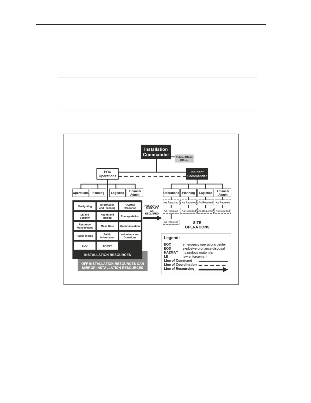
Chapter 3
3-10. There are two functional centers on the installation during an incident response. They are the incident
command post (ICP) and the EOC:
z
ICP. The ICP is responsible for on-scene response activities and is under the direction of the IC.
The IC reports to the installation commander.
z
EOC. The EOC is responsible for the entire installation-wide response to the event and provides
overall command and control (on behalf of the installation commander) of the incident.
Note. USAF organizations employ a third command and control node. This command and
control node includes the installation commander and key staff and is called the crisis action
team, which operates out of the ICP. This vital command and control node links ongoing
incident response actions with the execution of the installation mission operations and maintains
vital linkage with higher headquarters.
3-11. Figure 3-2 details the notional interfaces among the installation commander, the IC, the ICP, on-
scene operations, and the EOC. The ICP and the EOC are discussed in detail in the following text.
Figure 3-2. ICS interface
INCIDENT COMMAND POST
3-12. When an incident occurs, trained installation personnel initiate the ICS and establish an ICP for on-
site response. The ICP is the tactical-level, on-scene incident command and management organization and
is typically located at, or in the immediate vicinity of, the incident site.
3-13. Initial safety zones for the establishment of an ICP are defined in the most recent version of the
Department of Transportation Emergency Response Guidebook. The Emergency Response Guidebook
Table of Initial Isolation and Protective Action Distances provides first responders with initial guidance
until technically qualified emergency response personnel are available. Distances from the area of impact
show areas likely to be affected during the first 30 minutes after materials are spilled. The size of these
areas could increase with time.
3-4
TM 3-11.42/MCWP 3-38.1/NTTP 3-11.36/AFTTP 3-2.83
23 June 2014
Respond
3-14. The senior installation first responder on the scene of an incident who has the requisite training
implements the ICS. The responder assumes the role of the IC and is responsible for directing and
controlling resources by virtue of explicit legal, agency, or delegated authority. As the installation response
further progresses, the role of the IC may change hands as more qualified first responders arrive on-scene
or are appointed by the installation commander. At some point, a UC may be established depending on the
magnitude of the event or an incident of national significance.
Note. USAF installations employ fire emergency services as the IC for an incident involving two
or more response agencies. Security or medical forces may function as the IC when an incident
or accident involves only a medical or security response.
3-15. The IC is responsible for all aspects of the response, including developing incident objectives and
managing incident operations. The IC sets priorities and defines the ICS organization for the particular
response. Even if other positions are not assigned, the IC is designated. The IC may assign deputies, who
must have the same qualifications as the person for whom they work, as they must be ready to take over the
IC position at any time.
Note. The IC is solely the tactical commander of the incident and is in charge of running the
response and initial recovery for the event. The command of the installation remains with the
installation commander throughout the incident, and the installation commander is ultimately
responsible for all efforts on the installation.
EMERGENCY OPERATIONS CENTER
3-16. EOCs have SOPs for monitoring incident development. They provide the following functions,
consistent with DODI 6055.17:
z
COP. The EOC uses a COP and incident management system to execute and support actions
required by the IEM plan and to facilitate the coordination of incident information.
z
Interoperable communications. The EOC ensures interoperable communications that support
the first responder and first receiver missions of the Service component and are encouraged to
ensure interoperable communications with civil authorities.
z
Mass warning and notification. DOD installations maintain mass warning and notification
capabilities to warn personnel immediately, but no longer than
10 minutes after incident
notification and verification.
z
Continuous warning point. The heads of the DOD components ensure a continuous capability
that serves as the contact or warning point for emergency situations.
3-17. The EOC functions as an ICS liaison who coordinates support for the IC/ICP in all functional areas
and follow-on elements. The EOC controls functional-area response and installation support elements so
that taskings or requests from the incident site are supported, and it keeps higher headquarters informed.
Each installation EOC is NIMS-compliant while using the incident or UC system organizational structure
to provide a collaboration point and operations center for installation staff. The EOC supports the execution
of the IEM plan, the installation AT plan, other supporting plans, DSCA missions, operational/contingency
plans of assigned unit commanders, and the NRF.
3-18. Just as every incident will not require the activation of the EOC, not every EOC activation will
invoke the full range of EOC capabilities. EOC activation levels (partial or full) can be scaled based on the
scope of the incident and the extent to which the EOC was already activated at the time of the incident. (For
example, if the EOC is already in a warm status of activation due to an exercise at the time of the incident.)
For more details on the TTP of the EOC, see appendix D.
MULTIAGENCY COORDINATION SYSTEM
3-19. As defined in NIMS, the Multiagency Coordination System is a combination of facilities, equipment,
personnel, procedures, and communications integrated into a common system with responsibility for
coordinating and supporting domestic-incident management activities. The Mulitagency Coordination
23 June 2014
TM 3-11.42/MCWP 3-38.1/NTTP 3-11.36/AFTTP 3-2.83
3-5
Chapter 3
System is focused on strategic and operational tasks at the installation level and on the support of the IC.
The primary Multiagency Coordination System functions are to support incident management policies and
priorities; facilitate logistics support and resource tracking; inform resource allocation decisions using
incident management priorities; manage incident-related information; and coordinate interagency and
intergovernmental issues regarding incident management policies, priorities, and strategies. The
Multiagency Coordination System provides central locations for operational information sharing and
resource coordination in support of on-scene efforts. Direct tactical and operational responsibility for
conducting incident management activities at the tactical level remains with the IC.
DEFENSE SUPPORT OF CIVIL AUTHORITIES
3-20. All DOD directives should be consulted before support is provided to civilian authorities. Usually,
the response to an emergency in the local community is the responsibility of local and state governments.
Military response occurs—
z
At the direction of the governor of the affected state for state National Guard forces.
z
Upon declaration by the President as requested by the governor of the affected state.
z
At the direction of Service secretaries for capabilities not assigned to geographic combatant
commanders (bases, installations).
z
Through immediate response authority.
3-21. Consistent with DODI 3020.52 and DODD 3025.18, the DOD, because of its capabilities and
resources, may be requested through established channels to provide temporary, short-duration emergency
support to civil authorities during an emergency when local and state resources have been overwhelmed
and RFAs have been submitted by civilian authorities via the procedures detailed in the NRF.
3-22. Consistent with DODD 3025.18, federal military commanders, heads of DOD components, and
responsible DOD civilian officials (referred to collectively as DOD officials) have immediate response
authority. “A Federal military commander’s, DOD Component Head’s, and/or responsible DOD civilian
official’s authority temporarily to employ resources under their control, subject to any supplemental
direction provided by higher headquarters, and provide those resources to save lives, prevent human
suffering, or mitigate great property damage in response to a request for assistance from a civil authority,
under imminently serious conditions when time does not permit approval from a higher authority within the
United States. Immediate response authority does not permit actions that would subject civilians to the use
of military power that is regulatory, prescriptive, proscriptive, or compulsory.”
3-23. There are several statutory authorities that DOD may use to provide support and be reimbursed.
These are detailed in JP 3-28, but the Homeland Security Act and the Stafford Act are discussed below:
z
Homeland Security Act. The Homeland Security Act was amended with respect to the
organization and mission of the FEMA in the Department of Homeland Security Appropriations
Act and established DHS as an executive department of the United States. The Homeland
Security Act consolidated component agencies, including FEMA, into the DHS. The Secretary
of Homeland Security is the head of DHS and has direction, authority, and control over it. All
functions of all officers, employees, and organizational units of DHS are vested in the Secretary.
z
Robert T. Stafford Disaster Relief and Emergency Assistance Act. The Robert T. Stafford
Disaster Relief and Emergency Assistance Act was also amended in the Department of
Homeland Security Appropriations Act. It describes the programs and processes by which the
federal government provides disaster and emergency assistance to state and local governments,
tribal nations, eligible private nonprofit organizations, and individuals affected by a declared
major disaster or emergency. The Robert T. Stafford Disaster Relief and Emergency Assistance
Act covers all hazards, including natural disasters and terrorist events.
z
Posse Comitatus Act. The Posse Comitatus Act prohibits federal, state, and local authorities
from using Title 10 forces for any direct civil LE activities unless a constitutional or act of
Congress exception applies. The Posse Comitatus Act does not prohibit federal forces from
assisting state and local organizations with humanitarian disaster relief.
3-6
TM 3-11.42/MCWP 3-38.1/NTTP 3-11.36/AFTTP 3-2.83
23 June 2014
Respond
3-24. Overseas installations coordinate their efforts with the supported geographic combatant command
and, consistent with geographic combatant command guidance and DODD 5530.3, with appropriate DOS
officials and HNs. DSCA does not apply to support in response to foreign disasters. (Refer to DODD
5100.46 and JP 3-29.) All international agreements comply with the procedures and regulations outlined in
DODD 5530.3.
3-25. DOD units supporting an installation emergency response will be under the command and control of
defense authorities, yet they may work in support of the civil authorities assisting the installation. The legal
considerations for emergency response on an installation are complex and vary by the location, affected
area, and incident type. Commanders consult their legal staff at the beginning of the planning process to
incorporate, understand, and train staffs and responders on the limitations that a particular installation
might face.
INTEGRATION OF SUPPORT ACTIVITIES
3-26. As outlined in DODI 6055.17 and the NRF, ESFs organize and provide structure to federal
interagency emergency response activities. Installations apply the ESF structure or equivalent functional
area structure to installation emergency planning. Installations have the latitude to choose an organizational
structure other than ESFs to provide functional area support to the emergency response effort. Details on
the ESFs are provided in the NRF and appendix C. Appendix C also contains guidance for using functional
areas in lieu of the ESF structure.
3-27. The following ESFs are outlined in the NRF:
z
Transportation.
z
Communications.
z
Public works and engineering.
z
Firefighting.
z
EM.
z
Mass care, emergency assistance, housing, and human services.
z
Logistics management and resource support.
z
Public health and medical services.
z
Search and rescue.
z
Oil and HAZMAT response.
z
Agriculture and natural resources.
z
Energy.
z
Public safety and security.
z
Long-term community recovery.
z
External affairs.
3-28. The support functions of communications and resource management are integral to the operation of
the EOC and are major, overarching components of NIMS. They are therefore discussed in more detail
below and in appendixes E and F, respectively. Appendix G contains a sample MAA support agreement,
while appendix H contains TTP on the support function for evacuation, SIP, and lockdown. Appendix I
contains TTP for the mass care support function.
COMMUNICATIONS
3-29. Communication needs during a response span from communicating with and among responders to
communicating emergency information to the installation community. The following elements of
communication are critical to ensuring timely, widespread, accurate information delivery throughout the
response effort.
23 June 2014
TM 3-11.42/MCWP 3-38.1/NTTP 3-11.36/AFTTP 3-2.83
3-7
Chapter 3
EMERGENCY PUBLIC INFORMATION
3-30. The construction and delivery of emergency public information (EPI) throughout an incident is
critical in creating and maintaining a resilient, trusting, empowered, and cooperative installation
community. The delivery of key EPI messages begins immediately after an incident occurs (as vetted
through the public affairs officer in the EOC, through the joint information center, or at higher
headquarters) and continues throughout response and recovery.
3-31. EPI is an ongoing process throughout all phases of EM and is designed to engage and inform
personnel potentially affected by an emergency. EPI is typically implemented through the use of a joint
information center.
3-32. In coordination with local civil jurisdictions, installation commanders preselect at least one primary
and one alternate site near the installation for the establishment of a joint information center. The preferable
site for a joint information center, in order to support joint and interagency staffing with federal, state,
local, and other authorities, is outside the jurisdictional boundaries of the installation. Locating the joint
information center outside installation boundaries is necessary to preserve the adequate exchange of public
information when and if the installation is closed to the public during an emergency.
3-33. The requirement for EPI does not end immediately after termination of the response phase of an
incident. There is a continued need to exchange information with the full range of affected public during
the recovery phase. Installations continue communication during recovery operations by providing
pertinent information, such as conveying the impact and analyses of the incident. Additionally, installations
provide opportunities for stakeholders to submit information on community impacts, lessons learned, and
other relevant information from the community, supporting local, state, and federal agencies; the media;
and members of the general public.
3-34. Providing pertinent information and assistance to military members, civilian employees, and their
families is extremely important. Military personnel will be better able to concentrate on mission recovery if
they are confident that their family needs (medical, housing, legal, counseling, pet care, food, clothing) are
being met. The primary method of providing this assistance is to activate an emergency family assistance
control center or similar assistance center. This serves as the focal point for family assistance services and
operates in conjunction with the installation EOC and appropriate ESFs and functional areas.
3-35. Using current guidelines, the installation can leverage social media to convey information and
monitor message response. Appendix E provides additional information regarding all aspects of
communications TTP, including EPI.
COMMON OPERATIONAL PICTURE
3-36. During the response phase, a common operational picture (COP) is established to provide the
installation commander and his staff with a quick, timely, usable, precise, and reliable view of the status of
an incident. As explained in DODI 6055.17, the COP provides consistency at all levels of incident
management across jurisdictions, as well as between various governmental jurisdictions and private-sector
and nongovernmental entities.
3-37. The COP is capable of supporting all aspects of response operations (hazard locations, evacuation or
SIP requirements and locations, unit response capabilities, unit exposure status, updated risk assessments)
to the greatest extent possible. To be effective, the COP is constantly updated during the response phase.
3-38. A key benefit of a good COP system is that it allows the installation to quickly relay to its tenant and
transient units the identical, graphic display of relevant information for SA. The same information can be
relayed to local officials. In the case of foreign operations, it is feasible that U.S. embassy personnel could
relay these details to HN representatives as appropriate. Thus, a good COP facilitates collaborative
planning throughout the response effort.
3-8
TM 3-11.42/MCWP 3-38.1/NTTP 3-11.36/AFTTP 3-2.83
23 June 2014
Respond
INCIDENT REPORTING
3-39. Incident reporting and documentation procedures are standardized to ensure that SA is maintained
and that EM and response personnel have easy access to critical information. Detailed instructions for
operational and situation reports can be found in Chairman of the Joint Chiefs of Staff (CJCS) Manual
3150.05C.
3-40. Situation reports offer a snapshot of the past operational period and contain confirmed or verified
information regarding the explicit details (who, what, when, where, how) relating to the incident. Status
reports, which may be contained in situation reports, relay information specifically related to the status of
resources (such as the availability or assignment of resources).
3-41. The information contained in incident notification, situation, and status reports is standardized to
facilitate processing without preventing the collection or dissemination of information unique to a reporting
organization. The transmission of data in a common format enables the passing of pertinent information to
appropriate jurisdictions and organizations and to a national system that can handle data queries and
information and intelligence assessments and analysis.
MASS WARNING AND NOTIFICATION
3-42. DODI 6055.17 directs installations to develop mass warning and notification capabilities to warn
personnel immediately, but no longer than 10 minutes after incident notification and verification. The mass
warning and notification gives response direction using intelligible voice communications, visible signals,
texts, text messaging, computer notification, and tactile or other communication methods. Mass warning
TTP are outlined in appendix E.
3-43. Based on the Report of the DOD Independent Review (Protecting the Force: Lessons from Fort
Hood) and the resulting Secretary of Defense Memorandum (Final Recommendations of the Fort Hood
Follow-on Review), DODI 6055.17 requires mass notification and warning systems to be a required
capability for installations to achieve IEM full operational capability. Existing and future elements may
include—
z
A giant voice for outdoor areas.
z
In-building speaker systems.
z
Telephone alert systems for phone calls and text alerts.
z
Software alert systems for computer and e-mail alerts.
DISPATCH/EMERGENCY CONTROL/EMERGENCY COMMUNICATIONS
3-44. The installation dispatch or emergency communications center provides emergency call taking; alarm
monitoring; sensor monitoring; video monitoring and control; communications support; channel, frequency
assignments, and allocation; and emergency notification to response personnel. In some cases, these
services are provided regionally or in collaboration with civil authorities.
3-45. DODI 6055.17 requires a capability for enhanced 9-1-1 service on the installation. Enhanced 9-1-1 is
a telephone system consisting of network, database, and enhanced 9-1-1 equipment that uses the single
three-digit number for reporting police, fire, medical, or other emergency situations to a central location,
while automatically associating a physical address with the telephone number of the calling party.
3-46. The 9-1-1 systems are interoperable with civilian authorities to allow incoming and outgoing
transfers of voice and location data. Dispatch centers include capabilities for interoperable communication,
weather monitoring, mass warning system control, and COP system access. Dispatch centers may also
include capabilities for the provision of emergency medical dispatch instructions and monitoring of the
National Warning System.
3-47. The IEM program coordinates plans with the responsible office for the dispatch function to ensure
that emergency notifications to responders are communicated in a timely manner. The dispatch center is
included in IEM exercises and training events as appropriate.
23 June 2014
TM 3-11.42/MCWP 3-38.1/NTTP 3-11.36/AFTTP 3-2.83
3-9
Chapter 3
RESOURCE MANAGEMENT
3-48. Resource management occurs at all levels in support of incident management. Installation resources
supply assets for installation level response efforts and potentially provide support for incident support base
and JRSOI missions. Support agreements are in place in advance of an event and are enacted during an
event as needed to maintain supplies.
SUPPLY AND LOGISTICS
3-49. Maintaining an accurate and up-to-date picture of resource availability and utilization is a critical
component of resource management. Resource management includes processes for categorizing, ordering,
dispatching, tracking, and recovering resources. Resource management also includes processes for the
reimbursement of resources, as appropriate.
3-50. As outlined in NIMS, incident management personnel use various resource inventory systems to
assess the availability of assets provided by public, private, and volunteer organizations. Installation
emergency managers are responsible for the consolidation of resource inventory entries and submissions by
assigned ESFs or functional areas. ESFs or functional areas on installations are responsible for entering the
resources available for deployment into the resource inventory maintained at the installation. This resource
data is made available to the supporting installation dispatch center and installation EOC. ESFs or
functional areas are also responsible for resource and financial management related to life cycle
management of assigned resources. For more information regarding resource management and resource
typing, see appendix F.
INCIDENT SUPPORT BASE
3-51. Installations selected as an incident support bases are expected to continue military mission
operations, in addition to those imposed by the incident support base mission. Installation commanders are
prepared to request personnel, material, and equipment augmentation as necessary. Incident support base
support is temporary in nature and uses resources not required for the preparation or conduct of military
operations.
3-52. The term incident support base is now used by DHS and FEMA to replace the previous terms of base
support installation, operational staging area, national logistics staging area, and mobilization site.
Consistent with DODD 3025.18 and JP 3-28, an incident support base is a DOD installation that provides
specified, integrated resource support to the DSCA.
3-53. Incident support base requirements from JP 3-28 and JP 3-41 state that an incident support base is a
DOD installation or leased facility of any DOD component which is in or near an actual or projected
domestic operational area and which has the capability to serve in general support of DOD forces involved
in civil disaster response operations.
3-54. The designation as an incident support base may require the installation to provide one or more
installation support roles, including ports of embarkation, ports of debarkation, intermediate staging bases,
and/or forward operating bases. Consistent with DODD 3025.18 and JP 3-28, incident support bases have
the following capabilities:
z
Close proximity to the incident site (less than 100 miles).
z
Close proximity to a major airfield.
z
Life support services (billeting, food service, fuel, contracting, medical support, FP).
z
Open and covered areas for the staging of supplies and equipment.
z
Adequate transportation network to and from the incident site.
z
Communications infrastructure sufficient to meet the surge of forces arriving in the area.
3-55. Depending on the nature and scope of assets organic to an installation, the installation may or may
not be requested to provide support in the form of an incident support base. However, every installation
commander is aware of the assets that may be requested of their installation in this event. In addition,
installation commanders understand the planning considerations for an installation to function as an
3-10
TM 3-11.42/MCWP 3-38.1/NTTP 3-11.36/AFTTP 3-2.83
23 June 2014
Respond
incident support base. Consistent with DODD 3025.18 and JP 3-28, incident support base planning
considerations take into account key functions of logistics for operations, including—
z
A concise concept of purpose and a description of the functions that the installation will support.
z
The forces required to support the operation and phasing for the induction of logistic elements.
z
A joint field office in the affected area.
z
A FEMA mobilization location.
z
The length of time that the installation will provide support.
z
Transportation suitability.
z
Adequate supply, maintenance, transportation, civil engineering, medical, and other service
support on the installation.
Note. For more details and a checklist on incident support base planning considerations, see JP
3-41.
3-56. To maximize the economy of force and to focus the response force on DSCA operations, the incident
support base is responsible for the JRSOI of forces flowing through the incident support base, as described
in detail below. JRSOI requirements are detailed in the mission assignment so that installations can
determine their ability to provide support.
JOINT RECEPTION, STAGING, ONWARD MOVEMENT, AND INTEGRATION
3-57. JRSOI is the critical link between the deployment and employment of response forces in an
operational area. The reception of forces and the subsequent staging at the incident support base are key to
the JRSOI.
3-58. Consistent with JP 3-41, the deploying force (usually a joint task force) utilizes organic assets when
possible to assist and expedite reception and staging operations. Depending on the size and scope of the
deploying response force, the incident support base may require additional equipment and personnel with
specialized capabilities to conduct JRSOI. Installations identify shortfalls in equipment, personnel, and
other resources through their operational chain of command. Special requirements of the deploying force
(such as armory or kennel services or classified material storage) are coordinated early in the planning
process to ensure their availability.
3-59. An incident support base may be tasked to support the medium- to large-scale staging of logistics
assets, including tractor trailers, portable facilities, and supply and logistic centers. An incident support
base may also be tasked to support the forward staging (mobilization site) of manpower and ground/air/sea
transportation assets for direct movement to the emergency site in place of the staging of heavy logistic
assets and depots.
3-60. IEM programs facilitate the planning for, preparing for, developing required capabilities for, and
supporting JRSOI during DSCA. However, the decision to designate an installation as an incident support
base or to provide support to JRSOI is dependent on whether or not the installation has the organic
capability to support those needs. The installation does not preplan for such a response until a standing
executive order directs the installation to do so.
ACTIVATION OF SUPPORT AGREEMENTS
3-61. Support agreements are activated through predetermined activation and reporting mechanisms to
meet the needs of the emergency incident. These agreements may be activated through the EOC or by the
on-scene IC as outlined by the agreement and IEM plan.
3-62. IEM plans include procedures for the eventual demobilization of supplied resources through existing
support agreements.
23 June 2014
TM 3-11.42/MCWP 3-38.1/NTTP 3-11.36/AFTTP 3-2.83
3-11
Chapter 3
SUMMARY
3-63. An incident may begin with or without a warning period; for example, an approaching hurricane
versus a sudden earthquake. As soon as an incident or the threat of an incident occurs, EM operations shift
from the planning and preparation mode to the response mode. When an incident or event begins, the
execution of NIMS and ICS procedures allows for a coordinated, interoperable, and expandable response
structure on and off the installation. The IC directs on-scene response activities from the ICP and reports to
the installation commander. The EOC manages support operations on behalf of the installation commander.
The coordination and integration of support activities, especially communications and resource
management, are integral to an efficient and effective incident response effort.
3-12
TM 3-11.42/MCWP 3-38.1/NTTP 3-11.36/AFTTP 3-2.83
23 June 2014

Chapter 4
Recover
There often is no distinct break between the time that response operations end and
recovery operations begin. Recovery often begins while response operations are still
in progress. In addition, recovery activities often extend long after the initial incident
response phase is complete. Short-term recovery actions seek to restore essential
services and ensure that the immediate needs of the impacted installation community
are met. Longer-term recovery actions include fully restoring remaining noncritical
operations, rebuilding destroyed property, and reconstituting other noncritical
services. The main goal of recovery is mission reconstitution and the restoration of
essential operations.
ACTIONS
4-1. The recover phase is depicted in figure 4-1.
Figure 4-1. Recover phase
23 June 2014
TM 3-11.42/MCWP 3-38.1/NTTP 3-11.36/AFTTP 3-2.83
4-1
Chapter 4
4-2. Table 4-1 provides an overview of recovery actions that are integral to an emergency response. Each
of these areas is discussed in further detail throughout this chapter.
Table 4-1. Recover phase functions and actions
Functions
Actions
Recovery management
•
Establish a recovery working group.
•
Conduct recovery planning, including establishing recovery
priorities.
Sustainment and restoration of
•
Sustain critical operations.
infrastructure and operations
•
Restore and/or maintain essential operations.
•
Sustain critical infrastructure.
•
Restore and/or maintain essential infrastructure.
•
Conduct damage assessments.
Mass care
•
Establish long-term housing/safe havens, including the
coordination of long-term feeding operations.
•
Support and manage behavioral health and counseling
operations.
Debris clearance and environmental
•
Conduct debris clearance operations.
remediation
•
Conduct environmental remediation operations.
Resource management
•
Manage the final disposition of resources.
•
Manage support agreements and contracts.
•
Manage emergency cost accounting.
Mortuary affairs
•
Support and manage mortuary affairs operations.
Public health
•
Coordinate a health risk assessment.
•
Manage risk mitigation.
•
Coordinate risk communication.
•
Manage the public health needs of safe havens.
•
Coordinate with mortuary affairs.
•
Evaluate and protect food and water supplies.
RECOVERY MANAGEMENT
4-3. In part, the NRF defines recovery as “ … the development, coordination, and execution of service-
and site-restoration plans; the reconstitution of government operations and services; individual, private-
sector, nongovernmental, and public-assistance programs to provide housing and to promote restoration;
long-term care and treatment of affected persons; additional measures for social, political, environmental,
and economic restoration; evaluation of the incident to identify lessons learned; postincident reporting; and
development of initiatives to mitigate the effects of future incidents.”
4-4. The primary tasks of an installation during the initial recovery phase are to complete any remaining
mitigation of the immediate hazard and finish restoring mission capability and essential public and
government services interrupted by an event. The primary tasks of an installation during long-term
recovery are to restore full operations and public services and to rebuild destroyed property.
RECOVERY WORKING GROUP
4-5. Consistent with DODI 6055.17, the installation commander establishes a recovery working group
early in the recovery phase of every emergency where recovery operations require coordination in the
judgment of the installation commander. The recovery working group is preidentified for likely events
within the IEM plans. The recovery working group is a task-organized working group focused on the
evaluation, prioritization, and coordination of recovery requirements. The recovery working group, with the
technical direction of the installation emergency manager and the installation public works/civil
engineering representative, conducts recovery planning at the installation level.
4-2
TM 3-11.42/MCWP 3-38.1/NTTP 3-11.36/AFTTP 3-2.83
23 June 2014

Recover
4-6. The recommended composition of the recovery working group is shown in table 4-2.
Table 4-2. Recommended composition of the recovery working group
Core Membership
Task-Specific
Optional
Public works
Airfield operations
Installation commander (or
Recreation services
Port operations
designee)
Installation emergency manager
Housing office
Reserve tenant commands
Installation PHEO
Information technology
DOD schools and daycare
Environmental
Chaplain
Engineering
Audit
Transportation
Tenant command representatives
Supply/logistics
Community group liaisons
LE
NGO liaisons
F&ES
EMS (if separate from F&ES)
Community/morale and welfare
services
Public affairs
Legal
Contracts
Health and safety
Legend:
DOD
Department of Defense
EMS
emergency medical services
F&ES
fire and emergency services
LE
law enforcement
NGO
nongovernmental organization
PHEO
public health emergency officer
RECOVERY PLANNING
4-7. During the recovery phase, additional information is obtained and a recovery plan is developed and
implemented. The recovery plan provides detailed, incident-specific procedures for short-term and long-
term recovery. The EOC uses the IEM plan to assist in developing a detailed recovery plan based on
damage assessment information and priorities established by the installation commander.
4-8. While the IEM plan facilitates response and short-term recovery, the recovery plan provides detailed,
incident-specific processes and procedures, including the immediate restoration of transportation and
communication capabilities, search and rescue operations, utility reconstruction, community reconstruction,
site remediation, medical care or mitigation, and other activities necessary for successful long-term
recovery.
4-9. During the transition to follow-on operations, the installation commander balances between focusing
resources on mission-essential tasks versus completing recovery tasks. Limitations of resources require
installation decisionmakers to prioritize and concentrate on the tasks needed to recover installation missions
and operations to full capability.
23 June 2014
TM 3-11.42/MCWP 3-38.1/NTTP 3-11.36/AFTTP 3-2.83
4-3
Chapter 4
4-10. As in the response phase, an up-to-date COP is invaluable during the recovery phase for providing
the installation commander and his staff with a quick, timely, usable, precise, and reliable view of the status
of an incident. During the recovery phase, the COP is capable of supporting all aspects of the recovery
operations (hazard locations, unit response capabilities, unit exposure status, updated risk assessments).
4-11. Long-term recovery after a major event usually takes years to complete. Installation commanders
establish recovery priorities consistent with the installation mission. Consideration is given to operational
mission priorities and the reestablishment of the normal operating environment, as well as activities such as
housing/facility construction, transportation restoration, community reconstruction, environmental
remediation, and continued delivery of EPI.
SUSTAINMENT AND RESTORATION OF INFRASTRUCTURE AND
OPERATIONS
4-12. The restoration of the installation infrastructure involves coordination with the installation public
works department and civilian jurisdiction service providers, public or private. IEM programs coordinate
infrastructure recovery plans before an incident to effectively restore infrastructure after the incident
occurs.
4-13. The restoration, in concert with mission continuation tasks, officially begins when the IC advises the
EOC director that the incident has been sufficiently controlled or terminated and the security of the
situation is sufficient to begin restoration activity. Consequently, the EOC directs and coordinates
infrastructure recovery inspections and reports damage by using “quick looks” and detailed assessments.
4-14. The damage assessment and impact analysis are essential to determining the magnitude, scope, scale,
and extent of an emergency. Damage assessment results guide the determination of priorities, identification
of required resources, and justification for assistance and supplemental funding requests. The public works
asset may conduct physical damage assessments, if such a capability exists within the installation.
Installations establish processes for damage assessment and debris clearance. These capabilities support
short-term (less than 2 weeks in duration) recovery efforts and initial damage assessments, resource
projections, and recovery planning requirements. The damage assessment process begins as soon as
possible after an incident occurs to assess the level of human suffering and infrastructure impacts and
continues throughout the recovery phase.
4-15. A reliable, rapid field damage assessment increases the likelihood that recovery funds and other
resources are properly prioritized and targeted. Damage assessments also provide policymakers with
guidance for planning and implementing mitigation measures. The field-based assessment acts as ground
truth for larger, more comprehensive assessments, such as satellite-based assessments. The objective of
rapid field damage assessments is to get a quick, reliable overview of the following damage-related issues:
z
Is there damage to the environment?
z
What is the damage to utilities and other supportive infrastructure?
z
Are there impacts to livelihood because of the damage?
z
What role, if any, did preincident mitigation measures play in reducing the impact of the
incident, and under what circumstances and to what extent did this occur?
4-16. After basic reconstruction activities have been completed, the long-term process of recovery begins.
Restoration decisions focus installation resources on critical and essential operations and infrastructure,
including maintaining safety, preventing the further loss of combat power, maintaining or restoring
installation integrity and security, restoring command and control over forces, restoring the primary
mission, and supporting other forces. Restoration capabilities include measures required to restore the
force, units, facilities, and equipment to near-normal operating conditions after a major accident or natural
disaster. These measures include decontamination operations and the effective supply and sustainment of
response assets.
4-17. Restoration actions, in progress or intended, are recorded and are a part of the recovery plan. From
this record, several actions are enabled. Those actions include estimating repair costs and determining
whether the repairs will be accomplished in-house or by contract, estimating the recovery date and time,
4-4
TM 3-11.42/MCWP 3-38.1/NTTP 3-11.36/AFTTP 3-2.83
23 June 2014
Recover
ascertaining required assistance, and assessing the impact on the combat readiness status of installation
forces.
MASS CARE
4-18. Care for the base populace during recovery includes providing temporary housing and behavioral
health and counseling services. Detailed TTP for mass care are included in appendix H, but the
fundamentals are discussed below.
HOUSING OPERATIONS
4-19. Temporary housing is where displaced personnel live from the time they leave a safe haven or
civilian shelter until the time they return to their previous home or a new home. Temporary housing is in a
livable condition; has sufficient utilities and services; is pest-, mold-, and mildew-free; and is properly
prepared (ventilated and cleaned) by safe-haven residents before occupancy. Before occupancy, personnel
need to fully understand the rules, timelines, and responsibilities concerning the use of temporary housing,
such as the expected occupancy time, financial responsibilities (utilities, damages, supplies, appliances),
general logistics (parking, utilities, supplies, quiet hours), and expected behavior. Examples of temporary
housing include barracks, dormitories, bachelor quarters, visitors quarters, previously available family
housing units, recreational lodging, hotels, rented apartments or homes in the local economy, mobile
homes, and vacation properties. The coordination of temporary housing needs is the responsibility of the
installation housing office in support of the recovery working group. Temporary housing needs for pets is
also considered and identified.
4-20. Installations should not rush into permanent housing solutions until a revised community profile has
been completed and the installation has the infrastructure and services necessary to support the estimated
population. It is important to address changes in the installation populace, especially designated place
relocations, during this process.
BEHAVIORAL HEALTH COUNSELING
4-21. A critical recovery operation that is often overlooked during the planning process is the provision of
behavioral health and counseling services to anyone affected by the incident in the installation community.
This important process begins the day of the incident and remains ongoing until full recovery is established.
The behavioral health and well-being of the installation community is the most vital component to a
complete and sustainable recovery effort.
DEBRIS CLEARANCE AND ENVIRONMENTAL REMEDIATION
4-22. Installations establish contracting vehicles to be used for debris clearance and environmental
remediation in the event of an incident requiring these services. These contracts include, but are not limited
to, MAA/MOU/MOA/ISSAs, indefinite quantity contracts, the logistics civil augmentation program, and
the emergency construction capabilities contract. Contracts should not be limited to local vendors or
commands, because these capabilities may be lost or overtasked during an emergency.
4-23. The debris management process begins as soon as possible after an incident occurs to permit access
to the incident site by designated personnel, to remove life safety and environmental hazards, and to
mitigate further environmental contamination throughout the recovery phase. Debris management
capabilities at an installation may be restricted by safety considerations and may be limited to providing
initial clearance operations and consolidating debris at one or more sites.
4-24. Remediation begins upon the completion of a contamination survey and continues until all
contamination has been removed or remediated. The scope and duration of the remediation depends on the
agent or material. The postevent assessment includes medical, environmental, and public works.
4-25. Remediation operations follow the neutralization and removal of CBRN contamination. Imminent
threats to personnel or the environment are alleviated during neutralization or removal operations, so
remediation operations normally take place in a nonemergency setting.
23 June 2014
TM 3-11.42/MCWP 3-38.1/NTTP 3-11.36/AFTTP 3-2.83
4-5
Chapter 4
4-26. Remediation is usually performed by civilian environmental consultant firms under contract to the
Service or under the supervision of the Environmental Protection Agency or the Department of Energy,
depending on the nature of the event. The identification, investigation, research, development, and cleanup
of contamination from hazardous substances, pollutants, and contaminants are to be carried out subject to,
and consistent with other federal regulatory guidance.
RESOURCE MANAGEMENT
4-27. Recovery involves the final disposition of all resources. During this process, resources are
rehabilitated, replenished, disposed of, and retrograded.
4-28. While many recovery activities can occur by utilizing organic and precoordinated capabilities
available to the installation, many longer-term recovery actions require external requests and coordination
for assets unavailable to a typical installation command. Consistent with DODI 3020.52, installation
commanders utilize reachback assets and support agreements to sustain and complete the recovery mission.
4-29. Resource management in recovery continues to include processes for categorizing, ordering,
dispatching, tracking, and demobilizing resources and personnel. Resource management during recovery
may also include processes for the reimbursement for resources, as appropriate.
4-30. Reimbursement provides a mechanism to fund critical needs that arise from incident-specific
activities. Reimbursement processes also play an important role in establishing and maintaining the
readiness of resources. Processes and procedures are in place to ensure that resource providers are
reimbursed in a timely manner. These include mechanisms for tracking expenditures, collecting bills,
validating costs against the scope of the work, ensuring that proper authorities are involved, and accessing
reimbursement programs.
4-31. Emergency cost accounting is a key function during an emergency. Emergency cost accounting can
be accomplished by the IC or EOC finance and administration sections or by another installation entity
after the EOC/IC are stood down. It is important to develop and standardize procedures to rapidly develop
and manage emergency cost accounting codes to track emergency-related expenses, including those
incurred under support agreements and support contracts. These emergency and special purpose codes are
issued by a designated Service authority. It is also important to consolidate and forward cost estimates
identified during the damage assessment process to the appropriate installation-owning command as
directed. It is the responsibility of installation-owning commands to develop the overarching emergency
funding lines necessary to consolidate multiple emergency cost account codes that may be in use by
multiple installations at the same time.
4-32. The installation business office or comptroller develops and approves procedures for expediting
fiscal decisions during emergencies consistent with established authorization levels and fiscal policy. This
framework provides for maximum flexibility to expediently request, receive, manage, and apply funds in a
nonemergency environment and in emergency situations to ensure the timely delivery of assistance. The
administrative process is documented through written procedures. The program is also capable of capturing
financial data for future cost recovery, as well as identifying and accessing alternative funding sources and
managing budgeted and specially appropriated funds.
MORTUARY AFFAIRS
4-33. Fatality management is a medical function with a logistics component regarding the management,
transportation, handling and, if necessary, temporary internment of human remains. Mortuary affairs is a
larger function of identifying the human remains; notifying and assisting the family of the deceased;
transporting the remains, if necessary; and conducting permanent interment. As discussed in DODI
6055.17, IEM programs coordinate with the supporting MTF and their logistics lead on the availability and
capabilities for fatality management.
4-34. IEM plans include predetermined responsibilities and procedures for the identification,
decontamination (if applicable), and handling of human remains, including mass fatality incidents. This
may require support from the civilian medical examiner in the event that installation assets are
overwhelmed.
4-6
TM 3-11.42/MCWP 3-38.1/NTTP 3-11.36/AFTTP 3-2.83
23 June 2014
Recover
4-35. Consistent with JP 4-06, mortuary affairs support may be requested by civil authorities in the event
of a mass casualty incident. The support provided by DOD mortuary affairs personnel is then tailored to the
needs of the requesting authority. The request could vary from personnel transporting human remains, to an
identification process, to a complete excavation of a disaster site.
PUBLIC HEALTH
4-36. The public health of the protected populace requires continued monitoring and actions throughout
recovery. Health risks, such as a lack of access to safe drinking water and safe and approved food sources
and animal feed, can severely disrupt the recovery process. The core functions of public health are health
risk assessment, risk mitigation, and communication of health risks to the public.
4-37. Other public health considerations include—
z
Establishing sanitary conditions for workers and residents.
z
Establishing vector control of mosquitoes, rats, and other disease vectors.
z
Managing mold and mildew assessments and removal operations necessary for housing
reoccupation.
z
Managing public health issues resulting from a lack of water treatment facilities.
z
Managing wastewater pump and treatment operations.
z
Managing solid waste collection and disposal operations.
z
Continuing syndromic surveillance operations.
z
Continuing medical surveillance of response personnel.
z
Expanding coverage to include personnel injured or exposed to hazardous conditions during
response and recovery operations.
z
Coordinating with mortuary affairs for the safe handling of human remains.
SUMMARY
4-38. Recovery is a long-term process that begins as an overlap with the response phase. Of the four
phases, recovery is the most time- and resource-intensive. Depending on the nature of the incident, full
community and economic recovery can take many months to many years and require significant budgetary
expenditures. Prioritizing the tasks necessary to recoup losses will help with time and budget management
as the installation commander and staff start down the long road to recovery.
23 June 2014
TM 3-11.42/MCWP 3-38.1/NTTP 3-11.36/AFTTP 3-2.83
4-7
This page intentionally left blank.
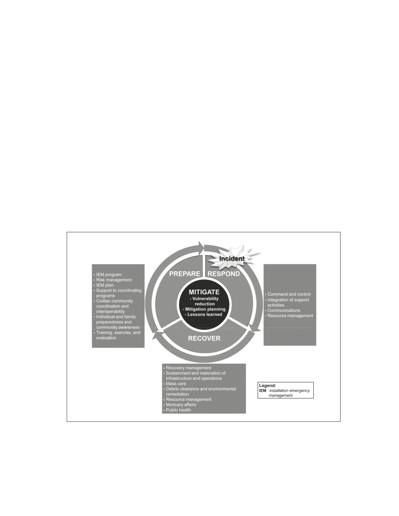
Chapter 5
Mitigate
Mitigation actions involve the lasting reduction of, exposure to, probability of, or
potential loss from identified hazards. The goal of mitigation efforts is to reduce the
impact of identified hazards on critical and essential operations, critical assets,
critical infrastructure, essential services, assigned personnel, and government and
personal property. Mitigation activities provide a critical foundation in the effort to
reduce injuries and the loss of life and property from natural and/or manmade
disasters by avoiding or lessening the impact of a disaster. Mitigation efforts are
taken before and after an emergency and should be an ongoing process that feeds
directly into the overall preparedness of the installation. Multiple functional areas
execute mitigation tasks as a normal part of their operations.
ACTIONS
5-1. The mitigate phase is depicted in figure 5-1.
Figure 5-1. Mitigate phase
23 June 2014
TM 3-11.42/MCWP 3-38.1/NTTP 3-11.36/AFTTP 3-2.83
5-1
Chapter 5
5-2. Table 5-1 outlines the major functions and corresponding activities associated with the mitigate
phase.
Table 5-1. Mitigate phase functions and actions
Functions
Actions
Vulnerability
• Understand and comply with zoning and building code requirements.
reduction
• Create inventories of existing structures and their vulnerabilities.
• Analyze hazard-related data to determine where it is safe to build in normal times, to
open shelters in emergencies, and to locate temporary housing in the aftermath of a
disaster.
• Educate businesses and the public on simple measures that they can take to reduce
loss and injury.
Mitigation
• Use results from the risk management process to understand inherent vulnerabilities
planning
of the installation.
• Coordinate pre- and postevent mitigation efforts through an installation mitigation
strategy.
• Ensure the integration of strategies and plans with applicable functional leads, on
and off the installation.
Lessons
• Document lessons learned in the AAR following an exercise, event, or incident.
learned
• Use lessons learned to construct an IP and a CAP.
• Share lessons learned with other entities (military and civilian) as appropriate.
Legend:
AAR
after action report
CAP
corrective action plan
IP
improvement plan
VULNERABILITY REDUCTION
5-3. Vulnerability reduction tools assist in the identification of mitigation efforts that may negate or
reduce the effects of identified hazards. Vulnerability reduction measures tie into the results from the risk
management process that takes place throughout the EM cycle (see appendix B).
5-4. Examples of vulnerability reduction and mitigation activities include—
z
Understanding and complying with zoning and building code requirements for rebuilding in
high-hazard areas.
z
Creating inventories of existing structures and their vulnerabilities.
z
Analyzing hazard-related data to determine where it is safe to build in normal times, to open
shelters in emergencies, and to locate temporary housing in the aftermath of a disaster.
5-5. Vulnerability reduction also can involve educating businesses and personnel on the measures that
they can take to reduce loss and injury, such as fastening bookshelves, water heaters, and file cabinets to
walls to keep them from falling during earthquakes.
5-6. Key areas of concern regarding mitigation activities include—
z
Utility systems, especially power and water treatment distribution.
z
Dams and levees.
z
Lightning and power surge protection.
z
Landslide and mudslide containment structures.
z
Earthquake retrofit requirements.
5-7. Mitigation actions can be grouped into the following categories:
z
Prevention. Prevention actions are the administrative or regulatory actions or processes that
influence the ways in which land and buildings are developed and built. These actions also
include public activities to reduce hazard losses. Examples include planning and zoning,
5-2
TM 3-11.42/MCWP 3-38.1/NTTP 3-11.36/AFTTP 3-2.83
23 June 2014
Mitigate
building codes, capital improvement programs, open space preservation, and storm water
management regulations.
z
Property protection. Property protection actions involve the modification of existing buildings
or structures to protect them from a hazard or the removal of property from the hazard area.
Examples include acquisition, elevation, relocation, structural retrofits, storm shutters, and
shatter-resistant glass.
z
Public education and awareness. Public education and awareness actions inform and educate
the installation populace about hazards and potential ways to mitigate them. Such actions include
outreach projects, hazard information centers, and school-age and adult education programs.
z
Natural resource protection. In addition to minimizing hazard losses, natural resource
protection actions preserve or restore the functions of natural systems. These actions include
sediment and erosion control, stream corridor restoration, watershed management, forest and
vegetation management, and wetland restoration and preservation.
z
Emergency services. Emergency service actions protect people and property during and
immediately after a disaster or hazard event. Services include warning systems, emergency
response services, and critical facility protection efforts.
z
Structural projects. Structural project actions involve the construction of structures to reduce
the impact of a hazard. Such structures include dams, levees, floodwalls, seawalls, retaining
walls, and safe rooms.
5-8. The role of the installation emergency manager in mitigation activities is to participate in planning
mitigation efforts under an integrated strategy through the IEMWG to ensure a cohesive and effective
effort. Mitigation activities are executed by the applicable functional leads. Mitigation phase activities draw
from a large number of resources established by federal and private sources. Many of these resources are
available at the FEMA mitigation Web site online and at the FEMA Building Science Branch Web site
online.
5-9. The installation coordinates pre- and postevent mitigation efforts with owners of specific
technological hazards (dams; levees; airfields; rail transportation systems; mass transit systems; ferry
systems; (petro) chemical facilities; related manufacturing, storage, or transportation systems) with the
potential or historical impact to the installation. A best practice for this process is to coordinate these
activities with the emergency managers of local civil jurisdictions.
5-10. Table 5-2 outlines potential hazard mitigation controls and techniques that can be utilized.
Table 5-2. Potential hazard mitigation controls and techniques
Hazard Type
Sample Mitigation Control Options
Tropical cyclones
• Installing hurricane straps to attach a roof to the walls and foundation.
• Installing storm shutters on windows.
• Implementing flood control measures (dams, levees, water runoff areas).
• Acquiring flood insurance (where applicable).
• Using concrete building materials.
• Raising foundation levels.
• Installing breakaway walls, windows, and doors.
Earthquakes
• Implementing earthquake-resistant building codes.
• Reinforcing buildings with steel frames.
• Installing vibration isolation bearings that are designed to dampen earthquake
ground movements before they reach the building to help the building move as
a unit.
• Bracing or supporting chimneys.
• Installing windows that use wider frames and include a compressible material
between the frame and the window glass to avoid direct contact between the
window and the frame.
23 June 2014
TM 3-11.42/MCWP 3-38.1/NTTP 3-11.36/AFTTP 3-2.83
5-3
Chapter 5
Table 5-2. Potential hazard mitigation controls and techniques (continued)
Hazard Type
Sample Mitigation Control Options
Tsunamis
•
Implementing early warning and notification capabilities, coupled with public
awareness regarding the actions to take when there is an earthquake or when
a tsunami watch or warning is issued.
•
Ensuring that people are ready to evacuate.
Volcanoes
•
Implementing early warning and notification capabilities, coupled with public
awareness regarding the actions to take when there is an eruption or a watch
or warning is issued.
•
Ensuring that people are ready to evacuate or shelter in place, depending on
the nature of the incident.
Tornadoes
•
Building safe rooms.
•
Installing early warning systems.
Chemicals hazards
•
Implementing mass warning and notification systems to instruct people to
(accidental or
evacuate or shelter in place.
intentional release)
•
Identifying the locations where HAZMAT is used and stored and ensuring that
proper procedures are in use by the facility.
Biological hazards
•
Offering vaccinations and/or mass prophylaxis.
(natural or intentional
•
Installing biological-agent detection sensors.
release)
•
Executing epidemiological surveillance measures.
Radiological hazards
•
Coordinating with LE and intelligence agencies.
(accidental or
•
Complying with laboratory safety and security guidelines and procedures.
intentional release)
•
Shelter in place, depending on the type or amount of radiation released
(alpha, beta, gamma).
Nuclear hazards
•
Coordinating with LE and intelligence agencies.
(accidental or
•
Complying with nuclear safety and security guidelines and procedures.
intentional release)
Explosives
•
Coordinating with LE and intelligence agencies.
•
Installing blast-resistant windows.
•
Establishing and implementing building standoff distances.
Wild fires (accidental
•
Clearing dead trees; brush; and tall, dry grass 30 feet from buildings and
or arson)
homes.
•
Planting fire-resistant trees and shrubs.
•
Keeping vegetation well-watered.
•
Landscaping with gravel.
•
Pruning tree limbs that are within 6 to 10 feet above the ground.
•
Constructing homes and buildings with noncombustible roof and siding (like
metal roofs and steel siding).
Legend:
HAZMAT
hazardous materials
LE
law enforcement
5-11. For more information on vulnerability reduction and mitigation activities, see the FEMA Mitigation
Best Practices Portfolio which is an online collection of case studies that depicts how organizations and
communities have worked to reduce or prevent damage from disasters.
MITIGATION PLANNING
5-12. According to FEMA, mitigation planning is the process used to identify risks and vulnerabilities
associated with natural disasters. It is also used to develop long-term strategies for protecting people and
property in future hazard events. The process results in a mitigation plan that offers a strategy for breaking
the cycle of disaster damage, reconstruction, and repeated damage and presents a framework for developing
5-4
TM 3-11.42/MCWP 3-38.1/NTTP 3-11.36/AFTTP 3-2.83
23 June 2014
Mitigate
feasible and cost-effective mitigation projects. Cost-effective mitigation measures are the key to reducing
disaster losses in the long term.
5-13. Mitigation planning is considered by the IEMWG with the technical direction of the installation
emergency manager and in coordination with appropriate functional area representatives (public works,
AT, information technology). While the functional area representatives are wholly responsible for the
planning and implementation of mitigation measures on the installation, the IEMWG mitigation plan
captures the interim and long-term actions and goals of the installation to reduce the impact of hazards and
threats that cannot be eliminated. A mitigation plan is a supporting plan to (or a plan element or component
of) the IEM plan. The best practice is to identify a mitigation committee of select members of the IEMWG
to create and maintain this plan.
5-14. The installation mitigation plan is used to guide the combined mitigation efforts of relevant
functional areas. It describes the physical, information technological, and nonmaterial mitigation strategies
associated with hazards identified during the risk management process.
5-15. A mitigation plan includes—
z
A discussion of the planning process and partners involved.
z
A discussion of the hazards and associated potential losses.
z
Goals aimed at reducing or avoiding losses from identified hazards.
z
Mitigation actions that help accomplish established goals.
z
Strategies that detail how the mitigation actions will be implemented and administered.
z
A description of how and when the plan will be updated.
LESSONS LEARNED
5-16. Just as with the evaluation of training or an exercise, lessons learned from a real-world incident on an
installation are documented and acted on to strengthen the IEM program and mitigate effects of future
incidents. Immediately following an incident, installation staff who were active in the response and
recovery efforts participate in a debriefing activity to capture best practices and lessons learned for
inclusion in an AAR on the incident.
5-17. The AAR includes recommendations for the remediation of current IEM practices to reflect lessons
learned during the incident. AARs also include dissemination and notification of successes and shortfalls,
installation-wide response checklists, deficiencies, deficiency correction plans, required training efforts,
implementation dates, corrective actions, follow-up actions, and lessons learned. Higher headquarters
establishes internal after-action reporting procedures to ensure that reporting objectives are met, problems
are solved, and results are disseminated.
5-18. As outlined in NIMS and HSEEP, lessons learned documented in the AAR are used to construct an
IP and CAP, as described below. The IP and CAP are used (at a minimum) to restructure the IEM plan for
better readiness and response.
5-19. The IP converts lessons learned from the incident into concrete, measurable steps that result in
improved EM capabilities. It specifically details the actions that will be taken to address each
recommendation presented in the AAR, who or what agency will be responsible for taking the action, and
the timeline for completion.
5-20. The CAP tracks and assesses progress on enhancing preparedness and incorporating information into
the emergency planning process. This process may identify needs for additional coordination, plans,
procedures, organization, manning, training, equipment, and exercises. The CAP includes the incorporation
of recommendations into updates to the risk management process and the annual revision of the IEM plan
consistent with DODI 6055.17. The CAP is closed out when improvements have been implemented and
validated through subsequent exercises and records are maintained on file as appropriate.
5-21. Lessons learned are key outputs of the AAR and reflect best practices, consistent challenges and
issues, and recommended solutions based on the evaluation of the incident. The Joint Lessons Learned
Program is a knowledge-sharing process established to enhance joint capabilities through discovery,
knowledge development, implementation, and the sharing of lessons from joint operations, training events,
23 June 2014
TM 3-11.42/MCWP 3-38.1/NTTP 3-11.36/AFTTP 3-2.83
5-5
Chapter 5
exercises, and other activities. The Joint Lessons Learned Program applies to the full range of joint
operations, including training, exercises, experiments, real-world events, and other activities involving
DOD assets of the Armed Forces of the United States.
5-22. Installations are also encouraged to engage with the federal Lessons Learned Information Sharing
initiative and associated Web portal operated by DHS. The posting of lessons learned on the portal is
permitted if approved by the installation commander after a legal review by the installation legal office.
SUMMARY
5-23. Vulnerability reduction efforts are critical to implementing an effective mitigation strategy on an
installation. The installation emergency manager, through the IEMWG, participates in the development of
an installation mitigation strategy that is captured in the installation mitigation plan. This plan may support,
or be a component of, the IEM plan. Throughout the EM cycle, installation emergency managers
coordinate installation-wide mitigation efforts that are led by appropriate functional area representatives.
Following an event or exercise, installation staff captures lessons learned during response and recovery
phases and uses them to better inform their mitigation activities in the future. Lessons learned on an
installation and from other collaborating partners are integral to enhancing an installation mitigation
strategy.
5-6
TM 3-11.42/MCWP 3-38.1/NTTP 3-11.36/AFTTP 3-2.83
23 June 2014

Appendix A
Metric Conversion Chart
This appendix complies with AR 25-30 which states that weights, distances, quantities, and measures
contained in Army publications will be expressed in both U.S. standard and metric units. Table A-1 is
a metric conversion chart.
Table A-1. Metric conversion chart
United States. Units
Multiplied By
Equals Metric Units
Feet
0.30480000
Meters
Inches
0.02540000
Meters
Yards
0.91440000
Meters
Miles
1.60934400
Kilometers
Metric Units
Multiplied By
Equals United States Units
Meters
3.28080000
Feet
Meters
39.37000000
Inches
Meters
1.09361000
Yards
Kilometers
0.621371192
Miles
23 June 2014
TM 3-11.42/MCWP 3-38.1/NTTP 3-11.36/AFTTP 3-2.83
A-1
This page intentionally left blank.

Appendix B
Risk Management
IEM planning is predicated on threat/hazard, vulnerability, and capability
assessments. These assessments are used to evaluate the ability of an installation to
respond to a threat or hazard, protect the population on the installation, and
implement future strategies to mitigate risks.
PROCESS
B-1. Risk management is a continuous process of reviewing critical infrastructure, assets, missions,
hazards, threats, vulnerabilities, consequences, and existing response capabilities to determine what
additional actions are needed to achieve or maintain a desired level of readiness and to protect the
population on the installation. As shown in figure B-1, a full-scale risk assessment process is configured on
the probability of a threat or hazard occurring; the vulnerability of an installation against that threat or
hazard; the consequence or magnitude of negative effects of the threat or hazard; the relative value of
critical infrastructure, assets, and missions; and the existing response capabilities for the mitigation of
effects postevent.
Figure B-1. Risk assessment process
B-2. At a minimum, a risk assessment is dependent on a comprehensive, all-hazards process that
includes—
z
Hazard threat assessments.
z
A VA.
z
A capability assessment.
z
A risk evaluation.
23 June 2014
TM 3-11.42/MCWP 3-38.1/NTTP 3-11.36/AFTTP 3-2.83
B-1
Appendix B
B-3. A risk assessment may also include assessments of criticality, consequence, cost-benefit, and need.
Risk factors from these assessments are combined in a risk evaluation that qualifies and/or quantifies risks
and impacts future decisions for mitigation measures on an installation. When the resultant risk assessment
is expressed in a manner that delineates which hazards and threats have more risk, it is called a relative risk
assessment.
B-4. These assessments incorporate information and recommendations from a variety of sources
including, but not limited to, higher headquarters assessments, joint staff integrated VAs, CIP planning and
assessments, COOP planning activities, and exercise deficiencies.
B-5. As outlined in DODI 6055.17, the risk management process is performed and documented by the
IEMWG under the authority of the installation commander and in coordination with functional areas such
as AT, CBRN, and CIP. The completion of the risk management process occurs before the development of
the initial IEM plan or IEM plan update and is an ongoing process. Effective risk management requires
support from the IEMWG and, as appropriate, from state, local, and tribal governments; other military
Services; or HN partners in the local community.
B-6. The intent of the risk management process is not to fixate on a 100 percent solution or on the
resolution of every variable to a defined quantity, but rather to provide a context in which to view relative
risk across the entire enterprise in as much of an objective manner as possible, given the hazards. The risk
management process provides a logical process to prioritize the development of specific capabilities and
the application of limited financial and human resources to specific capabilities. Using the risk management
process, the IEMWG can prioritize investments into those capabilities most applicable to local conditions
and needs. The process identifies key preparedness, mitigation, and prevention opportunities, which reduce
overall risk to the installation.
B-7. Risk decisions are ultimately the responsibility of the installation commander and are made at the
lowest possible level, except in extreme circumstances. Leaders and staffs manage risk. Staff members
continuously look for hazards associated with their areas of expertise and then recommend controls to
reduce risks. The role of the IEMWG in the installation risk management process is to identify controls,
develop a process to implement them, recommend solutions to the installation commander, and implement
the resulting decision.
CRITICALITY ASSESSMENTS
B-8. Some Services use criticality (also referred to as critical asset or critical infrastructure) assessments
as inputs to their risk evaluation as shown in figure B-1, page B-1. In most cases, these criticality
assessments have already been developed by AT or CIP programs.
B-9. The criticality assessment evaluates command missions and functions capabilities and determines
mission impact or the consequence of the loss of assets that support command mission execution. Critical
assets can be people, physical entities, systems, or information that provides a service or capability. The
analysis examines those assets for which degradation or destruction impact the command ability to
complete its assigned missions or functions.
B-10. DODI
3020.45 describes the critical asset identification process
(also see JP
3-07.2). There are other assets that may not be critical to the execution of the mission or function that may
be identified in this criticality process and included in the overall risk assessment process. These noncritical
assets could include assets like high-population facilities, such as theaters, commissaries, and base
exchanges.
HAZARD AND/OR THREAT ASSESSMENTS
B-11. The development of an all-hazards threat assessment accomplishes two goals:
z
The identification of a comprehensive list of threats and hazards.
z
The likelihood or probability of occurrence of each threat or hazard. In the context of assessing
risk, the higher the probability or likelihood of a threat or hazard occurring, the higher the risk of
loss will be to the asset.
B-2
TM 3-11.42/MCWP 3-38.1/NTTP 3-11.36/AFTTP 3-2.83
23 June 2014
Risk Management
B-12. Consistent with DODI 6055.17, IEM considers all hazards that may impact the installation. These
hazards vary among installations. For example, hurricanes may be a significant natural hazard concern in
the Southeast Region, but not in the Pacific Northwest. Tsunamis are of concern in the Pacific Northwest,
but generally not in the Southeast. Toxic industrial materials are of concern at almost all installations.
FEMA recommends including several other factors into the hazard assessment, including the time available
until the onset of the hazard and the possibility of a single event to cascade and cause other failures. It is
also beneficial for installation EM programs to coordinate threat and hazard assessments with state, local,
and HN EM agencies.
B-13. The federal government has a number of hazard-specific organizations that provide hazard
information for specific geographic areas. Examples include—
z
National Weather Service.
z
National Hurricane Center.
z
National Climatic Data Center.
z
U.S. Geological Survey.
z
National Oceanographic and Atmospheric Administration.
z
U.S. Army Corps of Engineers.
z
U.S. Volcanic Observatories.
z
National Earthquake Hazards Reduction Program.
z
National Tsunami Hazards Reduction Program.
z
Radiological Emergency Preparedness Program.
z
Chemical Stockpile Emergency Preparedness Program.
z
FEMA Office for Domestic Preparedness.
z
Environmental Protection Agency.
z
Department of Transportation, National Response Center.
z
National Interagency Fire Center.
B-14. FEMA has a number of programs for consolidating and providing hazard information to state
governments. In addition, each state and local jurisdiction applying for federal grant funding completes a
thorough hazard assessment as part of the grant process. HN programs vary greatly, but most nations,
provinces, and cities include a hazard assessment as part of their EM or civil defense programs. See DODI
3020.52 for chemical, biological, radiological, nuclear, and high-yield explosives
(CBRNE)-specific
guidance.
B-15. Terrorism and sabotage threats to strategic, operational, and mission-essential assets are also
assessed. Installation commanders utilize existing threat assessment methods to gather and analyze the
threats potentially impacting the installation on an ongoing basis and no less than annually. Threat
information is integrated to meet the collective needs of EM, CBRNE preparedness, AT, CIP, and COOP
planning. Installation commanders continuously ensure that forces are trained to maximize the use of threat
assessments and intelligence derived from liaisons to civil and military LE and public safety agencies and
departments and from EM, meteorological, environmental, public health, and medical syndromic
surveillance processes and procedures.
B-16. Each Service maintains its own terrorist threat analysis capability. Although DOD threat levels may
only be set by the Defense Intelligence Agency (DIA), special investigation offices and information fusion
centers can provide valuable assessments to installation commands regarding terrorist threats for specific,
localized areas. The following are primary sources of terrorism threat assessment data that contribute to
indications and warnings for U.S. military forces:
z
Marine Corps Forces Intelligence Department (G-2) or Information Fusion Center. The
Assistant Chief of Staff, Intelligence (G-2) is the focal point for the intelligence support for FP-
related intelligence, information, and counterintelligence (CI) issues for U.S. Marine Corps
assets within their respective area of responsibility. The Information Fusion Center oversees the
correlation of LE information in order to provide a domestic summary consistent with other
DOD intelligence oversight directives.
23 June 2014
TM 3-11.42/MCWP 3-38.1/NTTP 3-11.36/AFTTP 3-2.83
B-3
Appendix B
z
Naval Criminal Investigative Service Multiple Threat Alert Center threat products.
Products include time-sensitive spot or suspicious activity reports, warning reports, CI terrorism
supplements, annual regional threat assessments, port threat assessments, and baseline study
reports.
z
Army Counterintelligence Center threat products. Products include monthly international
terrorism summaries, multidisciplined CI threat assessments, and Army Counterintelligence
Center information papers.
z
Air Force Office of Special Investigation threat products. Products include CI notes and the
Blue Line-a daily synopsis of global incidents of interest to Air Force personnel.
z
DIA Joint Intelligence Task Force for Combating Terrorism (JITF-CT). Disseminates
intelligence on foreign terrorist threats, including the specific warning of threats against DOD
personnel, facilities, and other DOD material resources. Additionally, DIA produces a threat
assessment triennially, or if required, more frequently.
z
Geographic combatant command area of responsibility. A specific supplement to the DIA-
produced global threats report.
z
DHS Federal Bureau of Investigation (FBI) intelligence and analysis reports. FBI field
intelligence groups are the hub of the FBI Intelligence Program. These reports contribute to local
and regional perspectives on threats and serve as the primary intelligence link between the FBI
and fusion centers.
z
DHS intelligence reports. Includes DHS daily open-source infrastructure reports, digital library
critical releases, advisory system threat levels, daily infectious disease reports, daily drug
trafficking and smuggling reports, central digests, and daily cyber reports.
VULNERABILITY ASSESSMENTS
B-17. Vulnerability is a measure of the robustness of in-place installation and asset safeguards that are
taken to prevent or mitigate a threat or hazard from impacting an installation. Vulnerabilities define the
weaknesses or susceptibilities of an installation, system, asset, or application and identify its dependencies
that could cause it to suffer a degradation or loss (incapacity to perform its designated function) as a result
of having been subjected to a certain level of threat or hazard effects. The VA consists of the determination
of the potential vulnerability of an installation or specific function to an identified hazard.
B-18. Vulnerabilities to a critical asset can result from a wide variety of factors (design and construction
flaws, environmental factors, proximity to other structures or systems, factors influencing accessibility,
personal behaviors of people working in or around the critical assets, operational practices associated with
the critical assets or the installation). Vulnerabilities of a critical asset can also be determined by
vulnerabilities to other assets or areas that are not in close proximity to the critical asset. For instance,
vulnerabilities in access or perimeter control of an installation may lead to an adversary gaining access to
the installation and, ultimately, to the critical asset located somewhere inside the installation.
B-19. Installation commanders conduct a local AT VA as outlined in DODD 2000.12 and DODI 2000.16
for facilities, installations, and critical nodes within their areas of responsibility on an annual basis or, as
required, more frequently. This VA addresses the broad range of threats to the installation and personnel.
Existing AT VAs are used to establish the vulnerability of an installation or specific function to terrorist
threats, but installation EM personnel still conduct a thorough VA for natural and manmade hazards not
included within the AT scope.
B-20. VAs of installations—
z
Focus on the overarching EM and AT programs of the command.
z
Determine asset-specific vulnerabilities applicable to particular threats and hazards.
z
Assess the vulnerability scope of an asset, such as a single weakness or multiple weaknesses in
the safeguard system.
z
Assess the degree of difficulty in exploiting the vulnerability.
z
Analyze installation structure and activities from the perspective of an adversary to obtain a
basis for understanding real vulnerabilities. This may be accomplished through written
questionnaires and surveys.
B-4
TM 3-11.42/MCWP 3-38.1/NTTP 3-11.36/AFTTP 3-2.83
23 June 2014
Risk Management
z
Are classified according to appropriate security classification guides.
z
Are disseminated for internal use at least annually.
B-21. Process tools and resources for conducting VAs include—
z
DOD O-2000.12-H, including checklists and aids.
z
The Joint AT Program Manager’s Guide.
z
DTRA AT VA team guidelines.
z
Preexisting higher headquarters assessments and DTRA joint staff integrated vulnerability
assessments, performed every 3 years for installations of greater than 300 personnel.
CONSEQUENCE ASSESSMENTS
B-22. Some Services also perform consequence assessments and use them as inputs to their risk evaluation
as shown in figure B-1, page B-1. The consequence assessment determines the potential consequences that
an identified hazard may have on an installation or on a specific function at the current level of EM
capability of the installation. Consequence assessments include estimates for deaths, injuries, rebuilding
infrastructure costs, and the magnitude of disruption in mission capabilities.
CAPABILITY ASSESSMENTS
B-23. The capability assessment determines the current level of EM capability of the installation based on
the integrated nonmaterial and material readiness of supporting functional areas. Capability assessments
factor in the mitigating effects of existing emergency response manpower, procedures, training, equipment,
and exercises to more accurately predict consequences. The capability assessment is especially important in
the identification of capability gaps (needs) that are addressed to reduce the consequence of a specific
hazard on an installation or on a specific function.
B-24. The objectives of the capability assessment are to—
z
Consider the range of identified and projected response capabilities necessary for responding to
a hazard.
z
List installation resources by type to provide an asset capability report.
z
Review policy, guidance, and planning documents to identify the organization mission-essential
tasks and functions assigned to the organization.
z
List installation personnel with a mission-essential task responsibility as identified in DODI
6055.17.
z
Identify costs associated with assessment outcomes for future budget planning.
RISK EVALUATIONS
B-25. Effective risk management requires that the assessment of each hazard be evaluated in terms of
vulnerability, consequence, and the capability of the installation to manage the resulting emergency. All
hazards are not equal in terms of probability or severity; therefore, risk evaluation can be used to establish
relative risk in order for the installation commander to conduct risk management across the entire
jurisdiction vice solely basing it on vulnerability or consequence of a specific hazard to a specific mission.
B-26. Risk factors resulting from assessments for the various threats and hazards to each critical
infrastructure asset mission are compared against each other to determine relative risks. This relative risk
evaluation assists in future resource allocation, prioritization, and acquisition planning. Costs and benefits
may need to be considered when deciding to acquire new resources.
B-27. Service-specific examples of risk evaluation templates and matrices are provided in table B-1, page
B-6; figure B-2, page B-7; figure B-3, page B-8; and table B-2, page B-9. The threats and hazards
evaluated in each figure are notional and represent a small fraction of the total risks that an installation may
need to evaluate. For details on using these tables and calculating risk, refer to Commander, Navy
Installations Command (CNIC) Instruction 3440.17; FM 5-19; Marine Corps Order 3440.9; and the Air
Force Hazard-Risk Assessment Tool.
23 June 2014
TM 3-11.42/MCWP 3-38.1/NTTP 3-11.36/AFTTP 3-2.83
B-5

Appendix B
Table B-1. U.S.N. relative risk evaluation matrix (notional data)
Threat Hazard
RC Factors
Factors
Terrorism
CI
CBRE
Threat/
V
C
Factors
Attacks
Natural
Hazard
Factors
Factors
RRF
(0.1, 1, 2,
T
H
(1 to 4)
Tech
Scenarios
(0.1 to 4.5)
(1 to 12)
10)
(0.1, 1, 2,
(0.1 to 12)
Hazards
10)
Nuclear
(2 to 8)
Attacks
(0.1 to 2)
Earth-
quake,
building
6
NA
4.0
1.25
4
NA
8
15.0
structural
collapse
Tsunami
6
NA
3.0
1.25
4
NA
8
11.3
Fire (forest,
wilderness,
6
NA
2.1
1.25
4
NA
8
7.9
urban
structural)
Transpor-
tation
accidents
(aircraft,
6
NA
2.0
1.25
6
NA
8
11.3
ship, barge,
rail,
vehicle,
bus)
Power
energy
6
NA
2.1
1.25
1
NA
8
2.0
utility
failure
HAZMAT
spill
6
NA
2.5
1.25
2
NA
8
4.7
release
Note. RRF = (CI) x (T or H) x (V) x [(C) (RC)]; templates and instructions are available in CNIC Instruction 3440.17 to evaluate
each factor in the relative risk calculation.
Legend:
C
consequence
CBRE
chemical, biological, radiological, and high-yield explosives
CI
critical infrastructure
CNIC
Commander, Navy Installations Command
H
hazard
HAZMAT
hazardous materials
NA
not applicable
RC
response capability
RRF
relative risk factors
T
threat
TECH
technical
V
vulnerability
B-6
TM 3-11.42/MCWP 3-38.1/NTTP 3-11.36/AFTTP 3-2.83
23 June 2014

Risk Management
Legend:
lb
pound
Figure B-2. USMC threat hazard matrix template (notional data)
23 June 2014
TM 3-11.42/MCWP 3-38.1/NTTP 3-11.36/AFTTP 3-2.83
B-7

Appendix B
Risk Assessment Matrix
Probability
Frequent
Likely
Occasional
Seldom
Unlikely
Severity
Category
A
B
C
D
E
Catastrophic
I
E
E
H
H
M
Critical
II
E
H
H
M
L
Marginal
III
H
M
M
L
L
Negligible
IV
M
L
L
L
L
Mitigation Matrix
Installation
State
Location of Installation Assessment
Date
Page_ of _
Fort Bravo
TX
Building 1600, 1st Batallion Chemical
9 Sep 09
1 of 1
Headquarters
Prepared by: Name, Rank or Grade, and Duty Position
Jonathan J. Johnson, GS-13, Installation Emergency Manager
Assess
Unit Organization
Identified Hazard
Assess
Initial Control Measures
Residual
Assigned or
(Be Specific)
Hazard
(Be Specific)
Hazard
Responsible
L
M
H
E
L
M
H
E
Severe weather
Activate EOC, contact
Lead unit will be
(tornado [called
National Weather
assigned to IFES.
supercells]); severe
Center, initiate first alert
IFES will coordinate
wind, heavy
system,
with off-post services
lightning, hail, and
call needed immediate
if MAA is initiated.
possible tornadic
first responders with
activity.
other responders on
standby.
Legend:
E
extremely
EOC
emergency operations center
GS
general schedule
H
high
IFES
installation fire and emergency services
L
low
M
moderate
MAA
mutual-aid agreement
Sep
September
TX
Texas
Figure B-3. USAF risk assessment and mitigation matrixes (notional data)
B-8
TM 3-11.42/MCWP 3-38.1/NTTP 3-11.36/AFTTP 3-2.83
23 June 2014