Toyota C-HR (2019 year). Manual - part 16
 

  Index      Toyota     Toyota C-HR - service manual 2019 year in english


Search            


Content   ..  14  15  16  17   ..


Toyota C-HR (2019 year). Manual - part 16


241

4-5. Using the driving support systems

4

Drivin

g

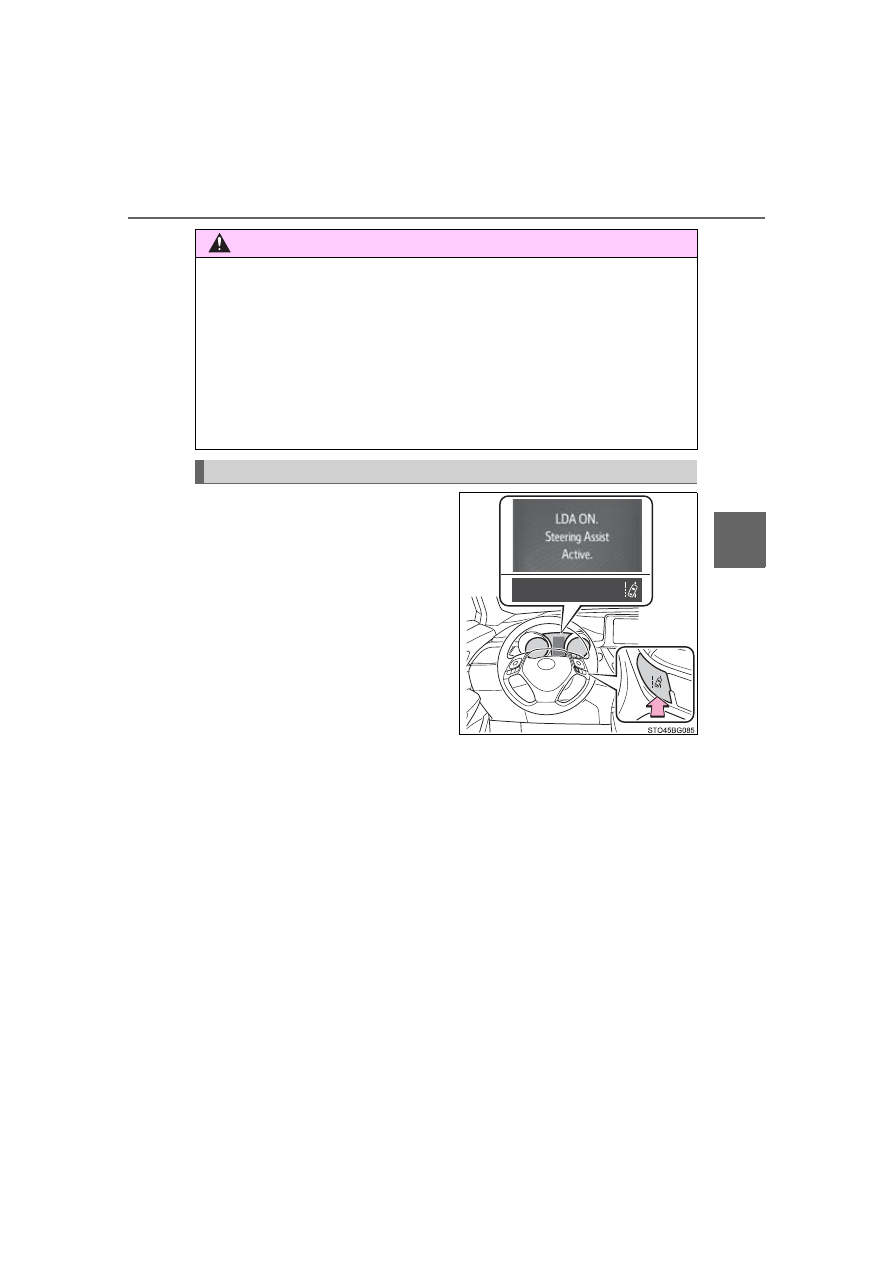
Press  the  LDA  switch  to  turn  the
LDA system on.

The  LDA  indicator  illuminates  and
a  message  is  displayed  on  the
multi-information display.
Press the LDA switch again to turn
the LDA system off.
When the LDA system is turned on
or off, operation of the LDA system
continues  in  the  same  condition
the next time the engine is started.

WARNING

Preventing  LDA  system  malfunctions  and  operations  performed  by
mistake

Do not modify the headlights or place stickers, etc., on the surface of the
lights.

Do  not  modify  the  suspension,  etc.  If  the  suspension,  etc.,  needs  to  be
replaced, contact your Toyota dealer.

Do not install or place anything on the hood or grille. Also, do not install a
grille guard (bull bars, kangaroo bar, etc.).

If your windshield needs repairs, contact your Toyota dealer.

Turning LDA system on

242

4-5. Using the driving support systems

LDA indicator

The  illumination  condition  of  the
indicator  informs  the  driver  of  the
system operation status.
Illuminated in white:
LDA system is operating.
Illuminated in green:
Steering  wheel  assistance  of  the
steering  control  function  is  operat-
ing.
Flashing in orange: 
Lane  departure  alert  function  is
operating.

Operation  display  of  steering
wheel operation support

Indicates that steering wheel assistance of the steering control function is
operating.

Lane departure alert function display

Displayed  when  the  multi-information  display  is  switched  to  the  driving
assist system information screen.

Indications on multi-information display

Inside  of  displayed  white  lines
is white

Inside of displayed white lines
is black

Indicates that the system is recog-
nizing  white  (yellow)  lines.  When
the  vehicle  departs  from  its  lane,
the  white  line  displayed  on  the
side  the  vehicle  departs  from
flashes orange.

Indicates  that  the  system  is  not
able  to  recognize  white  (yellow)
lines or is temporarily canceled.

243

4-5. Using the driving support systems

4

Drivin

g

Operation conditions of each function

Lane departure alert function
This function operates when all of the following conditions are met.
• LDA is turned on.
• Vehicle speed is approximately 32 mph (50 km/h) or more.
• System recognizes white (yellow) lines.
• Width of traffic lane is approximately 9.8 ft. (3 m) or more.
• Turn signal lever is not operated.
• Vehicle is driven on a straight road or around a gentle curve with a radius

of more than approximately 492 ft. (150 m).

• No system malfunctions are detected. (

P. 246)

Steering control function
This function operates when all of the following conditions are met in addi-
tion to the operation conditions for the lane departure alert function.

• Setting for “

 Steering Assist” in 

 screen of the multi-information

display is set to on. (

P. 493)

• Vehicle is not accelerated or decelerated by a fixed amount or more.
• Steering  wheel  is  not  operated  with  a  steering  force  level  suitable  for

changing lanes.

• ABS, VSC, TRAC and PCS are not operating.
• TRAC or VSC is not turned off.
• Hands off steering wheel alert is not displayed. (

P. 244)

Vehicle sway warning function
This function operates when all of the following conditions are met.

• Setting for “

 Alert” in 

 screen of the multi-information display is

set to on. (

P. 493)

• Vehicle speed is approximately 32 mph (50 km/h) or more.
• Width of traffic lane is approximately 9.8 ft. (3 m) or more.
• No system malfunctions are detected. (

P. 246)

244

4-5. Using the driving support systems

Temporary cancellation of functions
When the operation conditions are no longer met, a function may be tempo-
rarily canceled. However, when the operation conditions are met again, oper-
ation of the function is automatically restored. (

P. 243)

Steering control function
Depending  on  the  vehicle  speed,  lane  departure  situation,  road  conditions,
etc., the driver may not feel the function is operating or the function may not
operate at all.

Lane departure alert function
The warning buzzer may be difficult to hear due to external noise, audio play-
back, etc.

Hands off steering wheel alert

If the driver continues to keep their hands off of the steering wheel, a warning
message and the symbol shown in the illustration are displayed on the multi-
information  display,  and  the  function  is  temporarily  canceled.  This  warning
also  operates  in  the  same  way  when  the  driver  continuously  operates  the
steering wheel only a small amount. Always keep your hands on the steering
wheel when using this system, regardless of warnings.
Depending on the vehicle and road conditions, the warning may not operate.

Vehicle sway warning function 

Depending on the vehicle and road conditions, the warning may not operate. 

White (yellow) lines are only on one side of road
The  LDA  system  will  not  operate  for  the  side  on  which  white  (yellow)  lines
could not be recognized.

When  the  system  determines  that  the
driver  has  removed  their  hands  from  the
steering  wheel  while  the  steering  control
function is operating, a warning message
urging  the  driver  to  hold  the  steering
wheel and the symbol shown in the illus-
tration are displayed on the multi-informa-
tion display.

When  the  system  determines  that  the
vehicle is swaying while the vehicle sway
warning  function  is  operating,  a  buzzer
sounds  and  a  warning  message  urging
the driver to rest and the symbol shown in
the  illustration  are  simultaneously  dis-
played on the multi-information display.

245

4-5. Using the driving support systems

4

Drivin

g

Conditions in which functions may not operate properly
In the following situations, the camera sensor may not detect white (yellow)
lines and various functions may not operate normally.

There  are  shadows  on  the  road  that  run  parallel  with,  or  cover,  the  white
(yellow) lines.

The vehicle is driven in an area without white (yellow) lines, such as in front
of a tollgate or checkpoint, or at an intersection, etc.

The  white  (yellow)  lines  are  cracked,  “Botts’  dots”,  “Raised  pavement
marker” or stones are present.

The white (yellow) lines cannot be seen or are difficult to see due to sand,
etc.

The vehicle is driven on a road surface that is wet due to rain, puddles, etc.

The  traffic lines are yellow (which may be more difficult to  recognize  than
lines that are white).

The white (yellow) lines cross over a curb, etc.

The vehicle is driven on a bright surface, such as concrete.

The vehicle is driven on a surface that is bright due to reflected light, etc.

The  vehicle  is  driven  in  an  area  where  the  brightness  changes  suddenly,
such as at the entrances and exits of tunnels, etc.

Light from the headlights of an oncoming vehicle, the sun, etc., enters the
camera.

The vehicle is driven where the road diverges, merges, etc.

The vehicle is driven on a slope.

The vehicle is driven on a road which tilts left or right, or a winding road.

The vehicle is driven on an unpaved or rough road.

The vehicle is driven around a sharp curve.

The traffic lane is excessively narrow or wide.

The  vehicle  is  extremely  tilted  due  to  carrying  heavy  luggage  or  having
improper tire pressure.

The distance to the preceding vehicle is extremely short.

The vehicle is moving up and down a large amount due to road conditions
during driving (poor roads or road seams).

The headlight lenses are dirty and emit a faint amount of light at night, or the
beam axis has deviated.

The vehicle is struck by a crosswind.

The vehicle has just changed lanes or crossed an intersection.

Snow tires, etc., are equipped.

246

4-5. Using the driving support systems

Warning message
If the following warning message is displayed on the multi-information display
and  the  LDA  indicator  illuminates  in  orange,  follow  the  appropriate  trouble-
shooting procedure.

If a different warning message is displayed, follow the instructions displayed
on the screen.

Warning message

Details/Actions

“Lane Departure

Alert

Malfunction.

Visit Your Dealer.”

The system may not be operating properly.

 Have  the  vehicle  inspected  at  your  Toyota

dealer.

“Front Camera

Vision Blocked.

Clean and Demist

Windshield.”

Dirt,  rain,  condensation,  ice,  snow,  etc.,  are
present on the windshield in front of the camera
sensor.

 Turn  the  LDA  system  off,  remove  any  dirt,

rain,  condensation,  ice,  snow,  etc.,  from  the
windshield,  and  then  turn  the  LDA  system
back on.

“Front Camera

Unavailable.”

The operation conditions of the camera sensor
(temperature, etc.) are not met.

 When the operation conditions of the camera

sensor  (temperature,  etc.)  are  met,  the  LDA
system  will  become  available.  Turn  the  LDA
system  off,  wait  for  a  little  while,  and  then
turn the LDA system back on.

“LDA Unavailable.”

The LDA system is temporarily canceled due to
a malfunction in a sensor other than the camera
sensor.

 Turn  the  LDA  system  off  and  follow  the

appropriate  troubleshooting  procedures  for
the  warning  message.  Afterward,  drive  the
vehicle  for  a  short  time,  and  then  turn  the
LDA system back on.

“LDA Unavailable 
Below Approx. 32 

MPH (50km/h).”

The LDA system cannot be used as the vehicle
speed  is  approximately  less  than  32  mph  (50
km/h).

 Drive the vehicle at approximately 32 mph (50

km/h) or more.

247

4-5. Using the driving support systems

4

Drivin

g

Customization
The following settings can be changed.

For how to change settings, refer to P. 486.

Function

Setting details

Lane departure alert function

Adjust alert sensitivity

Steering control function

Turn steering wheel assistance on and off

Vehicle sway warning function

Turn function on and off

Adjust alert sensitivity

248

4-5. Using the driving support systems

Dynamic radar cruise controlwith full-speed 

range

In vehicle-to-vehicle distance control mode, the vehicle automatically
accelerates, decelerates and stops to match the speed changes of the
preceding vehicle  even  if  the accelerator  pedal  is  not  depressed.  In
constant speed control mode, the vehicle runs at a fixed speed.
Use  the  dynamic  radar  cruise  control  with  full-speed  range  on  free-
ways and highways.
● Vehicle-to-vehicle distance control mode (P. 251)
● Constant speed control mode (P. 258)

Vehicle-to-vehicle 

distance

switch
Display
Indicators
Set speed
Cruise control switch

Summary of functions

249

4-5. Using the driving support systems

4

Drivin

g

WARNING

Before using dynamic radar cruise control with full-speed range
Driving safely is the sole responsibility of the driver. Do not rely solely on the
system,  and  drive  safely  by  always  paying  careful  attention  to  your  sur-
roundings.
The  dynamic  radar  cruise  control  with  full-speed  range  provides  driving
assistance to reduce the driver’s burden. However, there are limitations to
the assistance provided.
Set the speed appropriately depending on the speed limit, traffic flow, road
conditions, weather conditions, etc. The driver is responsible for checking
the set speed.
Even when the system is functioning normally, the condition of the preced-
ing  vehicle  as  detected  by  the  system  may  differ  from  the  condition
observed  by  the  driver.  Therefore,  the  driver  must  always  remain  alert,
assess the danger of each situation and drive safely. Relying on this system
or assuming the system ensures safety while driving can lead to an acci-
dent, resulting in death or serious injury.

Cautions regarding the driving assist systems
Observe the following precautions, as there are limitations to the assistance
provided by the system.
Failure to do so may cause an accident resulting in death or serious injury.

Assisting the driver to measure following distance
The dynamic radar cruise control with full-speed range is only intended to
help the driver in determining the following distance between the driver’s
own vehicle and a designated vehicle traveling ahead. It is not a mecha-
nism that allows careless or inattentive driving, and it is not a system that
can  assist  the  driver  in  low-visibility  conditions.  It  is  still  necessary  for
driver to pay close attention to the vehicle’s surroundings.

Assisting the driver to judge proper following distance
The  dynamic  radar  cruise  control  with  full-speed  range  determines
whether  the  following  distance  between  the  driver’s  own  vehicle  and  a
designated vehicle traveling ahead is within a set range. It is not capable
of making any other type of judgement. Therefore, it is absolutely neces-
sary for the driver to remain vigilant and to determine whether or not there
is a possibility of danger in any given situation.

Assisting the driver to operate the vehicle
The dynamic radar cruise control with full-speed range has limited capabil-
ity to prevent or avoid a collision with a vehicle traveling ahead. Therefore,
if there is ever any danger, the driver must take immediate and direct con-
trol of the vehicle and act appropriately in order to ensure the safety of all
involved.

250

4-5. Using the driving support systems

WARNING

To  avoid  inadvertent  dynamic  radar  cruise  control  with  full-speed
range activation
Switch the dynamic radar cruise control with full-speed range off using the
“ON-OFF” button when not in use.

Situations unsuitable for dynamic radar cruise control with full-speed
range
Do not use dynamic radar cruise control with full-speed range in any of the
following situations.
Doing so may result in inappropriate speed control and could cause an acci-
dent resulting in death or serious injury.

Roads where there are pedestrians, cyclists, etc.

In heavy traffic

On roads with sharp bends

On winding roads

On slippery roads, such as those covered with rain, ice or snow

On steep downhills, or where there are sudden changes between sharp up
and down gradients 
Vehicle speed may exceed the set speed when driving down a steep hill.

At entrances to freeways and highways

When weather conditions are bad enough that they may prevent the sen-
sors from detecting correctly (fog, snow, sandstorm, heavy rain, etc.)

When there is rain, snow, etc., on the front surface of the radar sensor or
camera sensor

In traffic conditions that require frequent repeated acceleration and decel-
eration

During emergency towing

When an approach warning buzzer is heard often

251

4-5. Using the driving support systems

4

Drivin

g

This mode employs a radar sensor to detect the presence of vehicles
up  to  approximately  328  ft.  (100  m)  ahead,  determines  the  current
vehicle-to-vehicle following distance, and operates to maintain a suit-
able following distance from the vehicle ahead.

Note  that  vehicle-to-vehicle  distance  will  close  in  when  traveling  on  long
downhill slopes.

Driving in vehicle-to-vehicle distance control mode

252

4-5. Using the driving support systems

Example of constant speed cruising
When there are no vehicles ahead

The vehicle travels at the speed set by the driver. The desired vehicle-to-
vehicle  distance  can  also  be  set  by  operating  the  vehicle-to-vehicle  dis-
tance switch.

Example of deceleration cruising and follow-up cruising
When  a  preceding  vehicle  driving  slower  than  the  set  speed
appears

When a vehicle is detected running ahead of you, the system automatically
decelerates  your  vehicle.  When  a  greater  reduction  in  vehicle  speed  is
necessary, the system applies the brakes (the stop lights will come on at
this time). The system will respond to changes in the speed of the vehicle
ahead in order to maintain the vehicle-to-vehicle distance set by the driver.
Approach  warning  warns  you  when  the  system  cannot  decelerate  suffi-
ciently to prevent your vehicle from closing in on the vehicle ahead.
When the vehicle ahead of you stops, your vehicle will also stop (vehicle is
stopped by system control). After the vehicle ahead starts off, pushing the
cruise control lever up or depressing the accelerator pedal will resume fol-
low-up cruising.

Example of acceleration 
When  there  are  no  longer  any  preceding  vehicles  driving  slower
than the set speed

The system accelerates until the set speed is reached. The system then
returns to constant speed cruising.

253

4-5. Using the driving support systems

4

Drivin

g

Press  the  “ON-OFF”  button  to
activate the cruise control.

Radar  cruise  control  indicator  will
come  on  and  a  message  will  be
displayed  on  the  multi-information
display.
Press  the  button  again  to  deacti-
vate the cruise control.
If  the  “ON-OFF”  button  is  pressed
and held for 1.5 seconds or more,
the  system  turns  on  in  constant
speed control mode. (

P. 258)

Accelerate  or  decelerate,  with
accelerator  pedal  operation,  to
the desired vehicle speed (at or
above  approximately  30  mph
[50  km/h])  and  push  the  lever
down to set the speed.

Cruise  control  “SET”  indicator  will
come on.
The  vehicle  speed  at  the  moment
the  lever  is  released  becomes  the
set speed.
If  the  lever  is  operated  while  the
vehicle  speed  is  below  approxi-
mately  30  mph  (50  km/h)  and  a
preceding  vehicle  is  present,  the
set  speed  will  be  adjusted  to
approximately 30 mph (50 km/h).

Setting  the  vehicle  speed  (vehicle-to-vehicle  distance  control
mode)

1

2

254

4-5. Using the driving support systems

To change the set speed, operate the lever until the desired set speed
is displayed.

Increases the speed

(Except when the vehicle has been
stopped by system control in vehi-
cle-to-vehicle 

distance 

control

mode)

Decreases the speed

Fine  adjustment:  Momentarily
move  the  lever  in  the  desired
direction.
Large  adjustment:  Hold  the  lever  up  or  down  to  change  the  speed,
and release when the desired speed is reached.
In the vehicle-to-vehicle distance control mode, the set speed will be
increased or decreased as follows:

Fine adjustment: By 1 mph (1.6 km/h)

*

1

 or 1 km/h (0.6 mph)

*

2

 each time

the lever is operated

For the U.S. mainland, Hawaii

Large adjustment: Increases or decreases in 1 mph (1.6 km/h)

*

1

 or 1 km/h

(0.6 mph)

*

2

 increments for as long as the lever is held

For Canada, Guam and Puerto Rico

Large adjustment: Increases or decreases in 5 mph (8 km/h)

*

1

 or 5 km/h

(3.1 mph)

*

2

 increments for as long as the lever is held

In the constant speed control mode (

P. 258), the set speed will be

increased or decreased as follows:

Fine adjustment: By 1 mph (1.6 km/h)

*

1

 or 1 km/h (0.6 mph)

*

2

 each time

the lever is operated
Large  adjustment:  The  speed  will  continue  to  change  while  the  lever  is
held.

*

1

: When the set speed is shown in “MPH”

*

2

: When the set speed is shown in “km/h”

Adjusting the set speed

255

4-5. Using the driving support systems

4

Drivin

g

Pressing  the  switch  changes  the
vehicle-to-vehicle  distance  as  fol-
lows:

Long
Medium
Short

The  vehicle-to-vehicle  distance  is
set  automatically  to  long  mode
when the engine switch is turned to
the “ON” position (vehicles without
a  smart  key  system)  or  IGNITION
ON  mode  (vehicles  with  a  smart
key system).
If a vehicle is running ahead of you, the preceding vehicle mark will also be
displayed.

Select a distance from the table below. Note that the distances shown
correspond to a vehicle speed of 50 mph (80 km/h). Vehicle-to-vehicle
distance  increases/decreases  in  accordance  with  vehicle  speed.
When the vehicle is stopped by system control, the vehicle stops at a
certain vehicle-to-vehicle distance depending on the situation.

Changing the vehicle-to-vehicle distance (vehicle-to-vehicle dis-
tance control mode)

Preceding vehicle mark

Vehicle-to-vehicle distance settings (vehicle-to-vehicle distance
control mode)

Distance options

Vehicle-to-vehicle distance

Long

Approximately 160 ft. (50 m)

Medium

Approximately 130 ft. (40 m)

Short

Approximately 100 ft. (30 m)

256

4-5. Using the driving support systems

After  the  vehicle  ahead  of  you
starts off, push the lever up.
Your  vehicle  will  also  resume
follow-up  cruising  if  the  accelera-
tor  pedal  is  depressed  after  the
vehicle ahead of you starts off.

Pulling  the  lever  toward  you
cancels the speed control.

The speed control is also canceled
when 

the 

brake 

pedal 

is

depressed.
(When  the  vehicle  has  been
stopped 

by 

system 

control,

depressing  the  brake  pedal  does
not cancel the setting.)

Pushing the lever up resumes the cruise control and returns vehicle
speed to the set speed.

However,  when  a  vehicle  ahead  is  not  detected,  cruise  control  does  not
resume when the vehicle speed is approximately 25 mph (40 km/h) or less.

Resuming follow-up cruising when the vehicle has been stopped
by system control (vehicle-to-vehicle distance control mode)

Canceling and resuming the speed control


Content   ..  14  15  16  17   ..