Toyota C-HR (2019 year). Manual - part 17
 

  Index      Toyota     Toyota C-HR - service manual 2019 year in english


Search            


Content   ..  15  16  17  18   ..


Toyota C-HR (2019 year). Manual - part 17


257

4-5. Using the driving support systems

4

Drivin

g

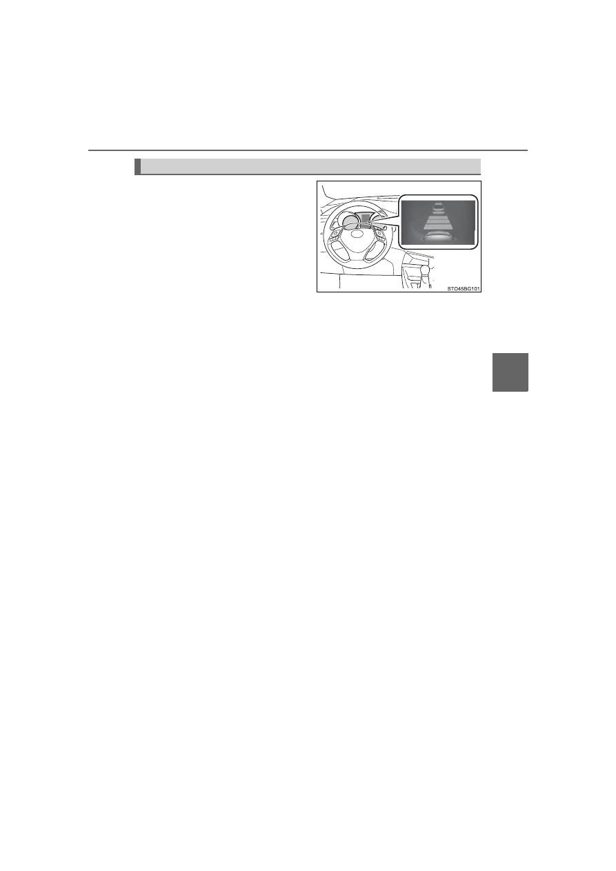
When your vehicle is too close to
a  vehicle  ahead,  and  sufficient
automatic  deceleration  via  the
cruise  control  is  not  possible,  the
display  will  flash  and  the  buzzer
will  sound  to  alert  the  driver.  An
example  of  this  would  be  if
another driver cuts in front of you
while you are following a vehicle.
Depress  the  brake  pedal  to
ensure  an  appropriate  vehicle-to-
vehicle distance.

Warnings may not occur when
In the following instances, warnings may not occur even when the
vehicle-to-vehicle distance is small.
● When  the  speed  of  the  preceding  vehicle  matches  or  exceeds

your vehicle speed

● When  the  preceding  vehicle  is  traveling  at  an  extremely  slow

speed

● Immediately after the cruise control speed was set
● When depressing the accelerator pedal

Approach warning (vehicle-to-vehicle distance control mode)

258

4-5. Using the driving support systems

When constant speed control mode is selected, your vehicle will main-
tain  a  set  speed  without  controlling  the  vehicle-to-vehicle  distance.
Select this mode only when vehicle-to-vehicle distance control mode
does not function correctly due to a dirty radar sensor, etc.

With  the  cruise  control  off,
press  and  hold  the  “ON-OFF”
button for 1.5 seconds or more.

Immediately  after  the  “ON-OFF”
button is pressed, the radar cruise
control  indicator  will  come  on.
Afterwards, it switches to the cruise
control indicator.
Switching  to  constant  speed  con-
trol  mode  is  only  possible  when
operating  the  lever  with  the  cruise
control off.

Accelerate  or  decelerate,  with
accelerator  pedal  operation,  to
the desired vehicle speed (at or
above  approximately  25  mph
[40  km/h])  and  push  the  lever
down to set the speed.

Cruise  control  “SET”  indicator  will
come on.
The  vehicle  speed  at  the  moment
the  lever  is  released  becomes  the
set speed.
Adjusting the speed setting: 

P. 254

Canceling and resuming the speed setting: 

P. 256

Selecting constant speed control mode

1

2

259

4-5. Using the driving support systems

4

Drivin

g

Dynamic radar cruise control with full-speed range can be set when

The shift lever is in D.

Vehicle speed is at or above approximately 30 mph (50 km/h).
However,  when a  preceding  vehicle is detected, the  dynamic  radar  cruise
control with full-speed range can be set even if the vehicle speed is at or
below approximately 30 mph (50 km/h).

Accelerating after setting the vehicle speed
The vehicle can accelerate by operating the accelerator pedal. After acceler-
ating,  the  set  speed  resumes.  However,  during  vehicle-to-vehicle  distance
control mode, the vehicle speed may decrease below the set speed in order
to maintain the distance to the preceding vehicle.

When the vehicle stops while follow-up cruising

Pushing  the  lever  up  while  the  vehicle  ahead  stops  will  resume  follow-up
cruising if the vehicle ahead starts off within approximately 3 seconds after
the lever is pushed up.

If the vehicle ahead starts off within 3 seconds after your vehicle stops, fol-
low-up cruising will be resumed.

Automatic cancelation of vehicle-to-vehicle distance control mode
Vehicle-to-vehicle distance control mode is automatically canceled in the fol-
lowing situations:

Actual vehicle speed falls at or below approximately 25 mph (40 km/h) when
there are no vehicles ahead.

The preceding vehicle leaves the lane when your vehicle is following at a
vehicle speed at or below approximately 25 mph (40 km/h). Otherwise, the
sensor cannot properly detect the vehicle.

VSC is activated.

TRAC is activated for a period of time.

When the VSC or TRAC system is turned off.

The sensor cannot detect correctly because it is covered in some way.

Pre-collision braking is activated.

The parking brake is operated.

The vehicle is stopped by system control on a steep incline.

The following are detected when the vehicle has been stopped by system
control:
• The driver is not wearing a seat belt.
• The driver’s door is opened.
• The vehicle has been stopped for about 3 minutes.

If vehicle-to-vehicle distance control mode is automatically canceled for any
other reason, there may be a malfunction in the system. Contact your Toyota
dealer.

260

4-5. Using the driving support systems

Automatic cancelation of constant speed control mode
Constant speed control mode is automatically canceled in the following situa-
tions:

Actual vehicle speed is more than approximately 10 mph (16 km/h) below
the set vehicle speed.

Actual vehicle speed falls below approximately 25 mph (40 km/h).

VSC is activated.

TRAC is activated for a period of time.

When the VSC or TRAC system is turned off.

Pre-collision braking is activated.

If constant speed control mode is automatically canceled for any other rea-
son, there may be a malfunction in the system. Contact your Toyota dealer.

Brake system operation sound
If the brakes are applied automatically while the vehicle is in vehicle-to-vehi-
cle  distance  control  mode,  a  brake  system  operation  sound  may  be  heard.
This does not indicate a malfunction.

Warning  messages  and  buzzers  for  dynamic  radar  cruise  control  with
full-speed range
Warning messages and buzzers are used to indicate a system malfunction or
to inform the driver of the need for caution while driving. If a warning message
is shown on the multi-information display, read the message and follow the
instructions.

When the sensor may not be correctly detecting the vehicle ahead
In  the  case  of  the  following  and  depending  on  the  conditions,  operate  the
brake  pedal  when  deceleration  of  the  system  is  insufficient  or  operate  the
accelerator pedal when acceleration is required.
As the sensor may not be able to correctly detect these types of vehicles, the
approach warning (

P. 257) may not be activated.

Vehicles that cut in suddenly

Vehicles traveling at low speeds

Vehicles that are not moving in the same lane

261

4-5. Using the driving support systems

4

Drivin

g

Vehicles with small rear ends (trailers with no load on board, etc.)

Motorcycles traveling in the same lane

When  water  or  snow  thrown  up  by  the  surrounding  vehicles  hinders  the
detecting of the sensor

When  your  vehicle  is  pointing  upwards
(caused by a heavy load in the luggage
compartment, etc.)

Preceding vehicle has an extremely high
ground clearance

262

4-5. Using the driving support systems

Conditions  under  which  the  vehicle-to-vehicle  distance  control  mode
may not function correctly
In the case of the following conditions, operate the brake pedal (or accelera-
tor pedal, depending on the situation) as necessary.
As the sensor may not be able to correctly detect vehicles ahead, the system
may not operate properly.

When the vehicle ahead of you decelerates suddenly

When driving on a road surrounded by a structure, such as in a tunnel or on
a bridge

While  the  vehicle  speed  is  decreasing  to  the  set  speed  after  the  vehicle
accelerates by depressing the accelerator pedal

When the road curves or when the lanes
are narrow

When  steering  wheel  operation  or  your
position in the lane is unstable

263

4-5. Using the driving support systems

4

Drivin

g

Driving mode select

Changing the driving mode

To select the drive mode, perform operations on the multi-information
display.

Press “

” or “” of meter control switches and select 

.

Press “

” or “” of the meter control switches, and select “Drive

Mode”.
Press  “

” or “” of the meter control switches, and select drive

mode.

In response to driving conditions, one of 3 drive modes can be
selected.

Select the drive mode

1

2

3

264

4-5. Using the driving support systems

Driving modes
● “NORMAL” mode

Provides  an  optimal  balance  of  fuel  economy,  quietness,  and
dynamic performance. Suitable for city driving.

● “SPORT” mode

Controls the transmission and engine to provide quick, powerful
acceleration. This mode also changes the steering feel, making it
suitable for when agile driving response is desired, such as when
driving on roads with many curves.

When  sport  mode  is  selected,  the  “SPORT”  indicator  will  illuminate
on the multi-information display.

● “ECO” mode

Helps  the  driver  accelerate  in  an  eco-friendly  manner  and
improve fuel economy  through moderate throttle characteristics
and  by  controlling  the  operation  of  the  air  conditioning  system
(heating/cooling).

When  Eco mode  is  selected,  the  “ECO MODE” indicator  will illumi-
nate on the multi-information display.
While  the  air  conditioning  is  being  used,  the  system  automatically
switches to air conditioning eco mode (

P. 297), allowing for driving

that leads to even better fuel economy.

Canceling driving modes

Select another drive mode. Also, “SPORT” mode will be canceled automati-
cally when the engine switch is turned off.

“NORMAL” mode and “ECO” mode will not be canceled automatically until
another drive mode is selected, even if the engine switch is turned off.

265

4-5. Using the driving support systems

4

Drivin

g

BSM (Blind Spot Monitor)

The Blind Spot Monitor is a system that has 2 functions;
● The BSM (Blind Spot Monitor) function 

Assists the driver in making the decision when changing lanes

● The RCTA (Rear Cross Traffic Alert) function 

Assists the driver when backing up

These functions use same sensors.

: If equipped

Summary of the Blind Spot Monitor

266

4-5. Using the driving support systems

Outside rear view mirror indicators

BSM function: 
When a vehicle is detected in a blind spot of the outside rear view mirrors
or approaching rapidly from behind into a blind spot, the outside rear view
mirror indicator on the detected side will illuminate. If the turn signal lever
is operated toward the detected side, the outside rear view mirror indicator
will flash.
RCTA function: 
When a vehicle approaching from the right or left at the rear of the vehicle
is detected, both outside rear view mirror indicators will flash.

Multi-information display

Turning the BSM function/RCTA function on/off. (

P. 267)

The RCTA function is available when the BSM function is on.

RCTA buzzer (RCTA function only)

If a vehicle approaching from the right or left at the rear of the vehicle is
detected, a buzzer will sound. The buzzer also sounds for approximately
1 second immediately after the BSM function is operated to turn the sys-
tem on.

“BSM” indicator/“RCTA” indicator

When  the  BSM  function/RCTA  function  is  turned  on,  the  indicator  illumi-
nates.

267

4-5. Using the driving support systems

4

Drivin

g

Press “

” or “” of the meter control switches, select 

.

Press “

” or “” of the meter control switches, select 

.

Press  “

”  or  “”  of  the  meter  control  switches,  select 

  or

.

The outside rear view mirror indicators visibility
When under strong sunlight, the outside rear view mirror indicator may be dif-
ficult to see.

Hearing the RCTA buzzer
The  RCTA  buzzer  may  be  difficult  to  hear  over  loud  noises,  such  as  if  the
audio system volume is high.

When “Blind Spot Monitor Unavailable.” is shown on the multi-informa-
tion display
Water, snow mud, etc., may be built up in the vicinity of the sensor area of
bumper (

P. 269).

Removing  the  water,  snow,  mud,  etc.,  from  the  vicinity  of  the  sensor  area
bumper should return it to normal. 
Also,  the  sensor  may  not  function  normally  when  used  in  extremely  hot  or
cold weather.

When  “Blind  Spot  Monitor  System  Malfunction  Visit  Your  Dealer.”  is
shown on the multi-information display
There  may  be  a  sensor  malfunction  or  misaligned.  Have  the  vehicle
inspected by your Toyota dealer.

Turning the BSM function/RCTA function on/off

1

2

3

268

4-5. Using the driving support systems

Certification for the Blind Spot Monitor

For vehicles sold in U.S.A.

FCC ID: OAYSRR3A
This devise complies with part 15 of the FCC Rules. Operation is subject to
the following two conditions:
(1) This device may not cause harmful interference, and 
(2) this device must accept any interference received, including interference
that may cause undesired operation.
FCC Warning
Changes or modifications not expressly approved by the party responsible for
compliance could void the user’s authority to operate the equipment.

For vehicles sold in Canada

Applicable law: Canada 310
This device complies with Industry Canada licence-exempt RSS standard(s).
Operation is subject to the following two conditions: (1) this device may not
cause interference, and (2) this device must accept any interference, includ-
ing interference that may cause undesired operation of the device.
Frequency bands: 24.05 - 24.25GHz
Output power: less than 20 milliwatts

269

4-5. Using the driving support systems

4

Drivin

g

WARNING

Handling the radar sensor
One Blind Spot Monitor sensor is installed inside the left and right side of
the vehicle rear bumper respectively. Observe the following to ensure the
Blind Spot Monitor can function correctly.

If the warning message does not disappear, have the vehicle inspected
by your Toyota dealer.

Do not subject a sensor or its surrounding area on the rear bumper to a
strong impact.
If a sensor is moved even slightly off position, the system may malfunction
and vehicles may not be detected correctly.
In  the  following  situations,  have  your  vehicle  inspected  by  your  Toyota
dealer.
• A sensor or its surrounding area is subject to a strong impact.
• If  the  surrounding  area  of  a  sensor  is  scratched  or  dented,  or  part  of

them has become disconnected.

Do not disassemble the sensor.

Do not attach accessories or stickers to the sensor or surrounding area on
the bumper.

Do not modify the sensor or surrounding area on the bumper.

Do not paint the rear bumper any color other than an official Toyota color.

Keep  the  sensor  and  its  surrounding
area on the bumper clean at all times.
If  a  sensor  or  its  surrounding  area  on
the  rear  bumper  is  dirty  or  covered
with snow, the Blind Spot Monitor may
not  operate  and  a  warning  message
(

P. 267) will be displayed.

In  this  situation,  clear  off  the  dirt  or
snow  and  drive  the  vehicle  with  the
operation conditions of the BSM func-
tion  (

P.  272)  satisfied  for  approxi-

mately 10 minutes.

270

4-5. Using the driving support systems

The BSM function uses radar sensors to detect the following vehicles
traveling in adjacent lanes and advises the driver of the presence of
such vehicles via the indicators on the outside rear view mirrors.

Vehicles that are traveling in areas that are not visible using the out-
side rear view mirrors (the blind spots)
Vehicles that are approaching rapidly from behind in areas that are
not visible using the outside rear view mirrors (the blind spots)

BSM function

271

4-5. Using the driving support systems

4

Drivin

g

The areas that vehicles can be detected in are outlined below.

The range of each detection area is:

Approximately 1.6 ft. (0.5 m) to 11.5 ft. (3.5 m) from either side of
the vehicle

*

*

: The area between the side of the vehicle and 1.6 ft. (0.5 m) from the side

of the vehicle cannot be detected.

Approximately 3.3 ft. (1 m) forward of the rear bumper
Approximately 9.8 ft. (3 m) from the rear bumper
Approximately 9.8 ft. (3 m) to 197 ft. (60 m) from the rear bumper

*

*

: The greater the difference in speed between your vehicle and the detected

vehicle is, the farther away the vehicle will be detected, causing the out-
side rear view mirror indicator to illuminate or flash.

BSM function detection areas

272

4-5. Using the driving support systems

The BSM function is operational when
The BSM function is operational when all of the following conditions are met:

The BSM system is set to on (

P. 267)

The shift lever is in a position other than R.

Vehicle speed is greater than approximately 10 mph (16 km/h)

The BSM function will detect a vehicle when
The  BSM  function  will  detect  a  vehicle  present  in  the  detection  area  in  the
following situations: 

A vehicle in an adjacent lane overtakes your vehicle.

You overtake a vehicle in adjacent lane slowly.

Another vehicle enters the detection area when it changes lanes.

Conditions under which the BSM function will not detect a vehicle
The  BSM  function  is  not  designed  to  detect  the  following  types  of  vehicles
and/or objects:

Small motorcycles, bicycles, pedestrians, etc.

*

Vehicles traveling in the opposite direction

Guardrails, walls, signs, parked vehicles and similar stationary objects

*

Following vehicles that are in the same lane

*

Vehicles traveling 2 lanes away from your vehicle

*

*

: Depending on conditions, detection of a vehicle and/or object may occur.

WARNING

Cautions regarding the use of the system
The driver is solely responsible for safe driving. Always drive safely, taking
care to observe your surroundings.
The Blind Spot Monitor function is a supplementary function which alerts the
driver that a vehicle is present in the blind spot. Do not overly rely on the
Blind Spot Monitor function. The function cannot judge if it is safe to change
lanes, therefore over reliance could cause an accident resulting in death or
serious injury.
According  to  conditions,  the  system  may  not  function  correctly. Therefore
the driver’s own visual confirmation of safety is necessary.


Content   ..  15  16  17  18   ..