Suzuki Grand Vitara JB416 / JB420 / JB419. Service manual - part 370
 

  Index      Suzuki     Suzuki Grand Vitara JB416 / JB420 / JB419 - service and repair manual 2007 year


Search            copyright infringement  


Content   ..  368  369  370  371   ..


Suzuki Grand Vitara JB416 / JB420 / JB419. Service manual - part 370


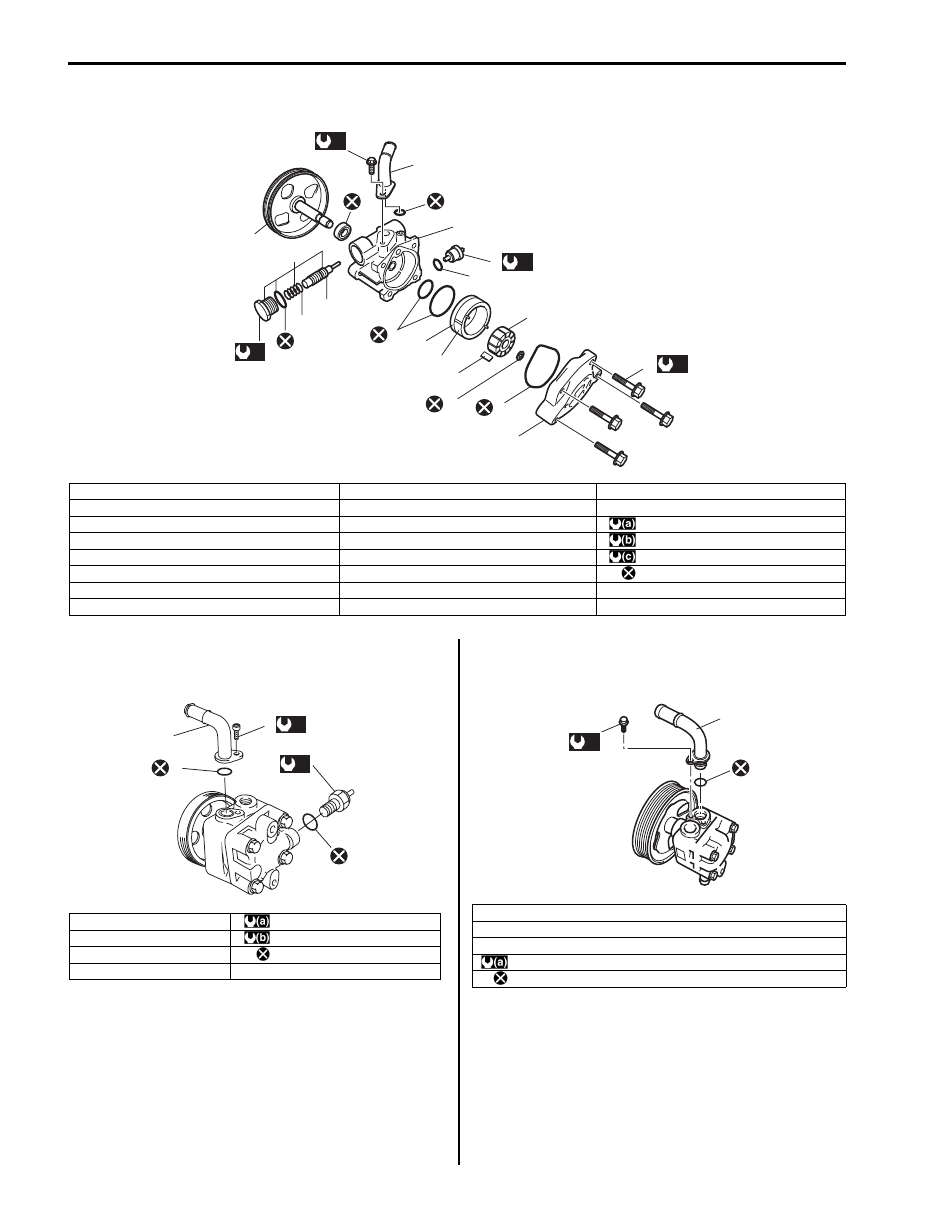
6C-23 Power Assisted Steering System: 

P/S Pump Components (M16A Engine Model)

S6JB0A6306021

P/S Pump Assembly Components (J20A Engine 
Model)

S6JB0A6306022

P/S Pump Assembly Components (F9Q Engine 
Model)

S6JB0A6306029

18

13

6

16

1

15

2

3

(c)

2

2

11

2

7

12

10

8

2

5

4

14

(a)

(a)

(b)

17

9

I5JB0A630003-01

1. Suction connector

9. Vane

17. Cover bolt

2. O-ring

10. Rotor

18. Suction connector bolt

3. Pressure switch

11. Snap ring

: 28 N

⋅m (2.8 kgf-m, 20.5 lb-ft)

4. Flow control valve (Relief valve)

12. Side plate

: 60 N

⋅m (6.0 kgf-m, 43.5 lb-ft)

5. Spring

13. Pulley (pump shaft)

: 12 N

⋅m (1.2 kgf-m, 9.0 lb-ft)

6. Plug

14. Oil seal

: Do not reuse.

7. Pump cover

15. Pump body

8. Cam ring

16. Flow control valve assembly

1. Suction connector

: 3.7 N

⋅m (0.37 kgf-m, 2.7 lb-ft)

2. O-ring

: 20 N

⋅m (2.0 kgf-m, 14.5 lb-ft)

3. Pressure switch

: Do not reuse.

4. Suction connector bolt

1

4

(a)

3

(b)

2

2

I5JB0A630029-03

1. Suction connector
2. O-ring
3.  Suction connector bolt

: 3.7 N

⋅m (0.37 kgf-m, 2.7 lb-ft)

: Do not reuse.

3

1

2

(a)

I5JB0B630008-01

Power Assisted Steering System:  6C-24

P/S Pump Disassembly and Assembly (M16A 
Engine Model)

S6JB0A6306023

Disassembly

1) Clean its exterior thoroughly.
2) With aluminum plates placed on vise first, grip pump 

body (15) with it.

3) Remove suction connector bolt, suction connector 

(1) and O-ring (2) from pump body (15).

4) Remove power steering pressure switch (terminal 

set) (3) from pump body (15).

5) Remove plug (6), flow control spring (5) and relief 

valve (flow control valve) (4) from pump body (15).

6) Remove cover bolts, pump cover (7) and O-ring (2) 

from pump body (15).

7) Remove snap ring (11) from pump shaft (13).
8) Remove vanes (9) from rotor (10).
9) Remove cam ring (8), rotor (10), side plate (12) and 

O-rings (2) from pump body (15).

10) Pull out pulley (13) from pump body (15).

11) Remove oil seal (14) from pump body (15).

Assembly

1) Apply grease to oil seal (1) lip and apply P/S fluid to 

sliding surface of the shaft (2) then insert pulley’s 
shaft (2) from oil seal side of the pump body.

“A”:  Grease 99000–25010 (SUZUKI Super 
Grease A) 

2) Apply power steering fluid to O-rings (1) and fit them 

to pump body.

3) Install side plate and cam ring and side plate (1) to 

pump body.

NOTE
Carefully align the dowel pins on the cam 
ring and side plate (1) at bolt hole (2) as 
shown in the figure.


1

13

14

6

2

5

4

15

2

12

9

2

3

8

10

11

7

2

I5JB0A630030-02

IYSQ01630041-01

1

I5JB0A630031-01

1

2

I5JB0A630032-01

6C-25 Power Assisted Steering System: 

4) Apply power steering fluid to sliding surface of rotor 

(1).

5) Install rotor (1) to shaft, directing dot (3) marked side 

of rotor facing up.

6) Install new snap ring (2) to shaft, then make sure to 

fit snap into shaft groove securely.

NOTE
Never reuse the removed snap ring (2).


7) Apply power steering fluid to sliding surface of cam 

ring (1).

8) Apply power steering fluid to each vane (2).
9) Install vanes (2) (10 pieces) to rotor (1).

10) Apply power steering fluid to O-ring (1).

11) Install O-ring (1) to pump body.

12) Apply power steering fluid to sliding surface of pump 

cover and rotor.

13) Match the dowel pins (1) to the holes of the cover 

plate (2) as shown and install pump cover to pump 
body.

14) Gradually tighten pump cover (1) bolts to diagonally 

specified torque.

NOTE
After installing pump cover (1), check to 
make sure that shaft can be turned by hand.


Tightening torque
P/S pump cover bolt (a):  28 N·m (2.8 kgf-m, 20.5 
lb-ft)

15) Apply power steering fluid to O-ring (2) of pressure 

switch.

16) Install O-ring (2) to pressure switch.
17) Install pressure switch (1) to pump body.

Tightening torque
Pressure switch (M16A engine model) (a):  28 
N·m (2.8 kgf-m, 20.5 lb-ft)

1

3

1

2

I5JB0A630033-01

2

1

I5JB0A630034-01

1

I5JB0A630035-01

1

2

I5JB0A630036-01

IYSQ01630049-01

1, (a)

2

I5JB0A630037-04

Power Assisted Steering System:  6C-26

18) Apply power steering fluid to relief valve (flow control 

valve).

19) Install relief valve (flow control valve) to pump body.
20) Install flow control spring.
21) Apply power steering fluid to O-rings of plug.
22) Install O-rings to plug.
23) Tighten plug to specified torque.

Tightening torque
Plug (a):  60 N·m (6.0 kgf-m, 43.5 lb-ft)

24) Apply power steering fluid to O-ring (2) of suction 

connector (1).

25) Install O-ring (2) to suction connector (1).

26) Install suction connector (1) to pump body as shown 

in the figure.
Tighten suction connector (1) bolts to specified 
torque.

Tightening torque
Suction connector bolt (M16A engine model) 
(a):  12 N·m (1.2 kgf-m, 9.0 lb-ft)

P/S Pump Inspection (M16A Engine Model)

S6JB0A6306024

Pump Body, Cover, Side Plate and Shaft
Check sliding surfaces of each part for wear and 
damage. If any defect is found, replace pump assembly.

Cam Ring
Check vane sliding surface of cam ring for wear and 
damage. If any defect is found, replace pump assembly.

IYSQ01630051-01

IYSQ01630052-01

1

(a)

I5JB0A630038-02

I5JB0A630051-01

IYSQ01630055-01


Content   ..  368  369  370  371   ..