Suzuki Grand Vitara JB416 / JB420 / JB419. Service manual - part 371
 

  Index      Suzuki     Suzuki Grand Vitara JB416 / JB420 / JB419 - service and repair manual 2007 year


Search            copyright infringement  


Content   ..  369  370  371  372   ..


Suzuki Grand Vitara JB416 / JB420 / JB419. Service manual - part 371


6C-27 Power Assisted Steering System: 

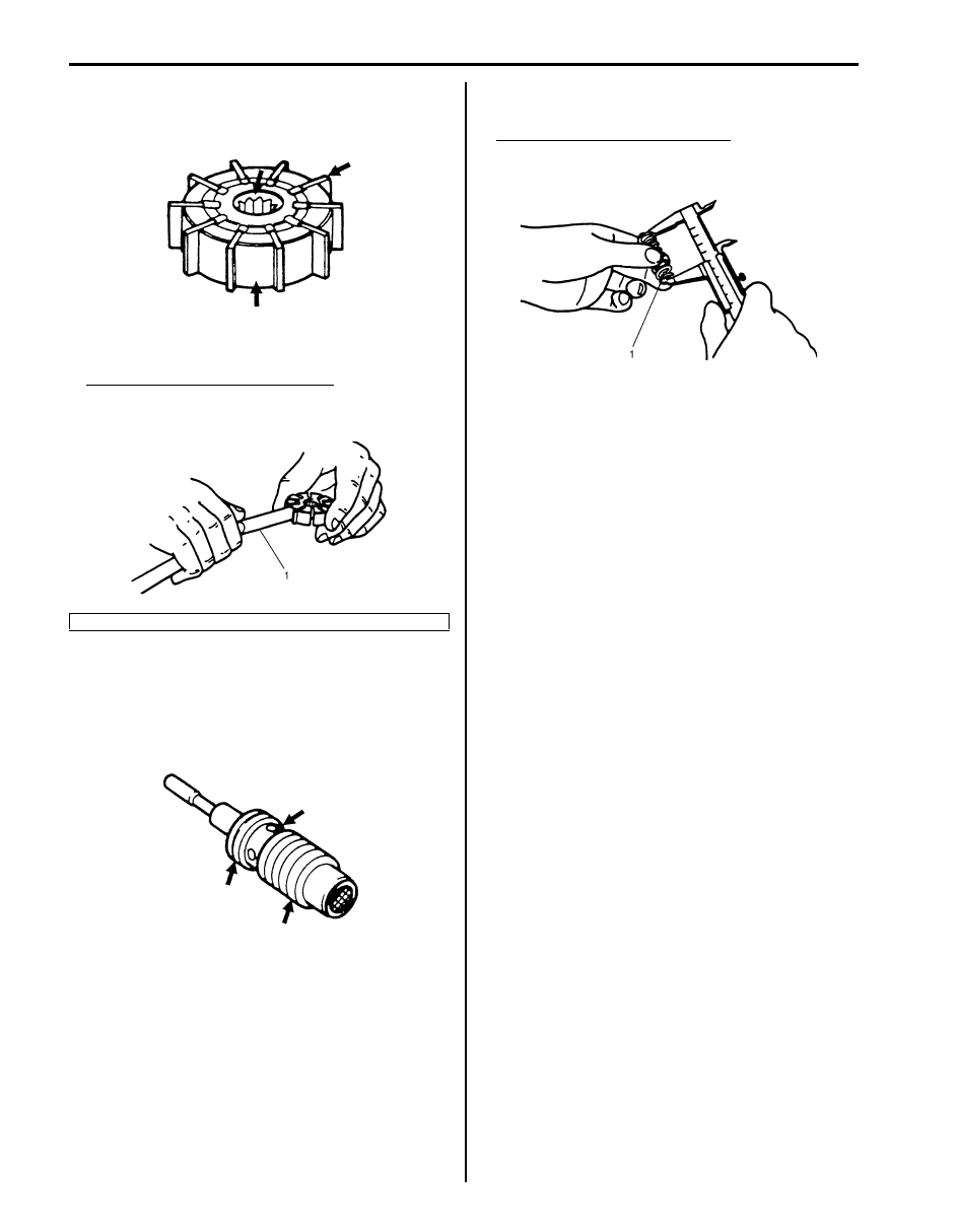
Rotor and Vane
• Check sliding surfaces of rotor and vane for wear and 

damage.

• Check clearance between rotor and vane. Replace 

pump assembly if any defect is found.

Clearance between rotor and vane
Standard: 0.015 mm (0.0006 in.)
Limit: 0.027 mm (0.0011 in.)

Relief Valve (Flow Control Valve) and Its Spring
• Check fluid passage of relief valve and orifice of 

connector for obstruction (clogged).

• Check sliding surface of relief valve for wear and 

damage.

• Check free length of relief valve spring (1). Replace if 

any defective is found.

Free length of relief valve spring
Standard: 22.0 mm (0.866 in.)
Limit: 19.0 mm (0.748 in.)

P/S Pump Inspection (J20A Engine Model)

S6JB0A6306025

Check P/S pump as follows.
• Damage of pump body.
• Oil leakage from pump body.
• Wear and damage of pulley.
• Abnormal noise when pulley is turned by hand.
If abnormality is found, replace P/S pump with new one.

P/S Pump Inspection (F9Q Engine Model)

S6JB0A6306030

Check P/S pump as follows.
• Damage of pump body.
• Oil leakage from pump body.
• Wear and damage of pulley.
• Abnormal noise when pulley is turned by hand.
If abnormality is found, replace P/S pump with new one.

1. Thickness gauge

IYSQ01630056-01

IYSQ01630057-01

IYSQ01630058-01

IYSQ01630059-01

Power Assisted Steering System:  6C-28

Specifications

Tightening Torque Specifications

S6JB0A6307001

NOTE
The specified tightening torque is also described in the following.
“P/S Gear Case Assembly Components”
“P/S Hose / Pipe Components”
“P/S Pump Components (M16A Engine Model)”
“P/S Pump Assembly Components (J20A Engine Model)”
“P/S Pump Assembly Components (F9Q Engine Model)”


Reference:
For the tightening torque of fastener not specified in this section, refer to “Fastener Information in Section 0A”.

Fastening part

Tightening torque

Note

N

m

kgf-m

lb-ft

P/S belt tension pulley bolt

25

2.5 

18.5

)

P/S belt tension pulley nut

25

2.5 

18.5

)

Tie-rod end nut

43

4.3 

31.0

)

Wheel nut

100

10.0 

72.5

)

Tie-rod end lock nut

65

6.5 

47.0

)

Steering lower shaft bolt

25

2.5 

18.5

)

Gear case high pressure pipe union bolt

35

3.5 

25.5

)

Gear case cylinder pipe flare nut

25

2.5 

18.0

)

Gear case mounting bolt

105

10.5 

76

)

Gear case low pressure pipe union bolt

40

4.0 

29.0

)

Stabilizer bar mount bracket mount bolt

60

6.0 

43.0

)

Gear case low pressure pipe flare nut

35

3.5 

25.5

(F9Q engine model) )

P/S pump bracket bolt

55

5.5 

40.0

(F9Q engine model) )

Tie-rod ball nut

90

9.0 

65.0

)

P/S pump mounting bolt

25

2.5 

18.0

)

 / ) / )

High pressure pipe union bolt

60

6.0 

43.5

)

 / )

P/S pump high pressure pipe union bolt

60

6.0 

43.0

)

P/S pump cover bolt

28

2.8 

20.5

)

Pressure switch (M16A engine model)

28

2.8 

20.5

)

Plug

60

6.0 43.5

)

Suction connector bolt (M16A engine model)

12

1.2 

9.0

)

6C-29 Power Assisted Steering System: 

Special Tools and Equipment

Recommended Service Material

S6JB0A6308001

NOTE
Required service material is also described in the following.
“P/S Gear Case Assembly Components”


Special Tool

S6JB0A6308002

Material

SUZUKI recommended product or Specification

Note

Grease

SUZUKI Super Grease A

P/No.: 99000–25010

)

Thread lock cement

Thread Lock Cement 1305

P/No.: 99000–32100

)

09913–75821

09915–77412

Bearing installer attachment

Oil pressure gauge

)

)

09915–77420

09943–88211

Oil pressure gauge 
attachment and hose set

Pinion bearing installer

)

)

09945–55410
Bushing installer
)

 / )

Table of Contents 7- i

7

Section 7

CONTENTS

HVAC

Precautions .................................................7-1

Precautions............................................................. 7-1

Precautions for HVAC........................................... 7-1

Heater and Ventilation............................. 7A-1

General Description .............................................7A-1

Heater and Ventilation Construction ................... 7A-1
Body Ventilation Construction............................. 7A-2
Additional Heater System Description (Diesel 

Engine Model)................................................... 7A-2

On-Board Diagnostic System Description (for 

Vehicle without A/C).......................................... 7A-3

HVAC Control System Description (for 

Vehicle without A/C).......................................... 7A-3

Schematic and Routing Diagram........................7A-4

Heater and Ventilation Wiring Circuit Diagram .... 7A-4
Electronic Control Input / Output Diagram (for 

Vehicle without A/C).......................................... 7A-4

Additional Heater System Input / Output 

Diagram (Diesel Engine Model) ........................ 7A-4

Component Location ...........................................7A-5

Electronic Components Location for Heater 

(for Vehicle without A/C) ................................... 7A-5

Additional Heater System Component 

Location (Diesel Engine Model) ........................ 7A-6

Diagnostic Information and Procedures............7A-6

Heater and Ventilation System Check ................ 7A-6
Visual Inspection................................................. 7A-8
DTC Check ......................................................... 7A-8
DTC Clearance ................................................... 7A-8
DTC Table........................................................... 7A-8
Fail-Safe Table.................................................... 7A-8
Scan Tool Data ................................................... 7A-8
Heater and Ventilation Symptom Diagnosis........ 7A-9

Repair Instructions ............................................7A-10

Blower Unit and Heater Unit Components ........ 7A-10
HVAC Unit Removal and Installation (for 

Vehicle without A/C)........................................ 7A-10

HVAC Air Filter Removal and Installation (for 

Vehicle without A/C)........................................ 7A-10

HVAC Air Filter Inspection (for Vehicle without 

A/C)................................................................. 7A-10

Blower Motor Removal and Installation.............7A-10
Blower Motor Inspection ...................................7A-11

Blower Motor Controller Removal and 

Installation .......................................................7A-11

Blower Motor Controller Inspection ...................7A-12
Blower Motor Relay Inspection .........................7A-12
Heater Core Removal and Installation ..............7A-12
Additional Heater Relay Inspection (Diesel 

Engine Model) .................................................7A-13

Additional Heater Assembly On-Vehicle 

Inspection (Diesel Engine Model) ...................7A-13

Additional Heater Assembly Removal and 

Installation (Diesel Engine Model)...................7A-14

HVAC Control Module Removal and 

Installation .......................................................7A-14

HVAC Control Module and Its Circuits 

Inspection (for Vehicle without A/C) ................7A-14

Air Flow Control Actuator Removal and 

Installation .......................................................7A-14

Air Flow Control Actuator Inspection.................7A-15
Temperature Control Actuator Removal and 

Installation .......................................................7A-15

Temperature Control Actuator Inspection .........7A-15
Air Intake Control Actuator Removal and 

Installation .......................................................7A-16

Air Intake Control Actuator Inspection...............7A-16
Actuator Linkage Inspection..............................7A-17
Center Ventilation Louver Removal and 

Installation .......................................................7A-17

Side Ventilation Louver Removal and 

Installation .......................................................7A-17

Rear Duct Components.....................................7A-18
Rear Duct Removal and Installation..................7A-18

Specifications.....................................................7A-19

Tightening Torque Specifications......................7A-19

Air Conditioning System......................... 7B-1

Precautions...........................................................7B-1

A/C System Caution............................................7B-1
Precautions on Servicing A/C System ................7B-1
Precautions in Diagnosing Trouble .....................7B-1
Precautions on Handling Refrigerant HFC-

134a (R-134a) ...................................................7B-1

Precautions on Servicing Refrigerant Line..........7B-2
Precautions on Refrigerant Recovery .................7B-3
Precautions on Refrigerant Charge.....................7B-3
Precautions on Replenishing Compressor Oil ....7B-3


Content   ..  369  370  371  372   ..