Suzuki Grand Vitara JB416 / JB420 / JB419. Service manual - part 223
 

  Index      Suzuki     Suzuki Grand Vitara JB416 / JB420 / JB419 - service and repair manual 2007 year


Search            copyright infringement  


Content   ..  221  222  223  224   ..


Suzuki Grand Vitara JB416 / JB420 / JB419. Service manual - part 223


2C-15 Rear Suspension: 

4) Remove rear coil spring referring to “Rear Coil 

Spring and Bump Stopper Removal and Installation”.

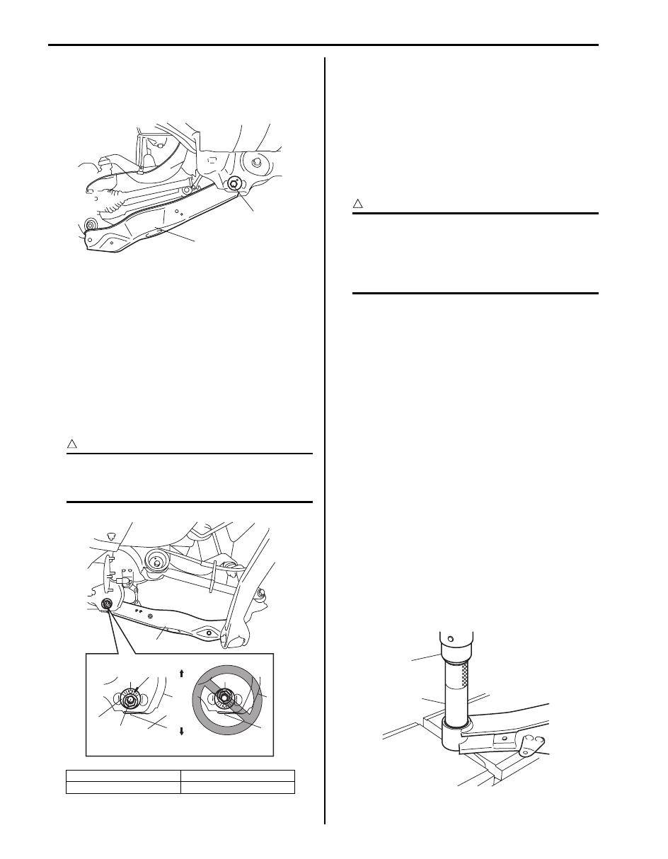
5) Remove suspension rod mount bolt (1) and then 

lower arm (2).

Installation

1) Install lower arm.

a) Install lower arm (1) to rear suspension frame.
b) Insert suspension lower arm inner bolt (2) from 

the vehicle rearward.

c) Install lower arm washer (3) with its graduated 

part facing up.

d) The marks (4) on lower arm washer (3) and rear 

suspension frame marked before its removal 
must be aligned and, tighten bolt and nut 
temporarily by hand.

CAUTION

!


If lower arm mount nut and lower arm outer 
bolt are reused, apply engine oil to thread 
and bearing and trunk surface.


2) Install rear coil spring referring to “Rear Coil Spring 

and Bump Stopper Removal and Installation”.

3) Install wheel with nuts and lower vehicle.
4) Tighten wheel nuts to specified torque.

Tightening torque
Wheel nut:  100 N·m (10.0 kgf-m, 72.5 lb-ft)

5) Tighten lower arm outer bolt and lower arm mount 

nut, shock absorber bolts to specified torque with 
vehicle weight on suspension.

CAUTION

!


• It is the most desirable to have vehicle off 

hoist and in non-loaded condition when 
tightening them.

• Tighten lower arm washer with match 

marks aligned.


Tightening torque
Lower arm outer bolt:  135 N·m (13.5 kgf-m, 98.0 
lb-ft)
Lower arm mount nut:  135 N·m (13.5 kgf-m, 98.0 
lb-ft)
Shock absorber lower bolt:  90 N·m (9.0 kgf-m, 
65.0 lb-ft)

6) Check rear toe and camber adjust it as necessary. 

For check and adjustment procedures, refer to “Rear 
Wheel Alignment Inspection and Adjustment”.

7) Adjust headlight auto leveling system, refer to 

“Initialization of Auto Leveling Headlight System in 
Section 9B”
.

Lower Arm / Bushing Disassembly and 
Assembly

S6JB0A2306015

Disassembly

1) Push out suspension lateral link bushing by using 

hydraulic press (1) and special tool.

Special tool
(A):  09913–84510

[A]: Correct

U: Upper side

[B]: Wrong

L: Lower side

2

1

I5JB0A230034-01

1

[A]

[B]

U

L

4

2

3

1

I5JB0A230035-02

1

(A)

I5JB0A230036-02

Rear Suspension:  2C-16

Assembly

1) Press-fit suspension lateral link bushing (2) by using 

press (1) and special tool.

CAUTION

!


Be sure to use new bushing.


Special tool
(A):  09913–85210

2) Press-fit bushing (1) so that dimension “A” and “B” in 

figure become equal.

Lower Arm Check

S6JB0A2306016

• Inspect for cracks, deformation or damage.
• Inspect bushing for wear and breakage.
If any faulty condition is found, replace.

Upper Arm Removal and Installation

S6JB0A2306017

Removal

1) Hoist vehicle and remove rear wheels.
2) Remove control rod refer to “Control Rod Removal 

and Installation”.

3) Remove trailing rod refer to “Trailing Rod Removal 

and Installation”.

4) Remove lower arm refer to “Lower Arm Removal and 

Installation”.

5) Remove rear suspension knuckle refer to “Rear 

Suspension Knuckle Removal and Installation”.

6) Remove wheel speed sensor clamp bolt (1) from 

upper arm (2).

7) Remove upper arm bolts (1) and then upper arm (2).

1

(A)

2

I5JB0A230083-01

I5JB0A230037-02

I5JB0A230038-01

1

2

I5JB0A230039-01

1

2

I5JB0A230040-01

2C-17 Rear Suspension: 

Installation

1) Install upper arm.

a) Install upper arm (2) to rear suspension frame.
b) Insert upper arm bolt (1) from the upper arm 

inside.

c) Tighten upper arm mount nuts (3) temporarily by 

hand.

CAUTION

!


If upper arm mount nut is reused, apply 
engine oil to thread and bearing.


2) Tighten wheel speed sensor clamp bolts (1) to 

specified torque.

Tightening torque
Wheel speed sensor clamp bolt (a):  11 N·m (1.1 
kgf-m, 8.0 lb-ft)

3) Install rear suspension knuckle refer to “Rear 

Suspension Knuckle Removal and Installation”.

4) Install trailing rod refer to “Trailing Rod Removal and 

Installation”.

5) Install control rod refer to “Control Rod Removal and 

Installation”.

6) Install lower arm refer to “Lower Arm Removal and 

Installation”.

7) Install rear wheels and lower hoist.
8) Tighten wheel nuts to specified torque.

Tightening torque
Wheel nut:  100 N·m (10.0 kgf-m, 72.5 lb-ft)

9) Tighten each bolts and nuts to specified torque with 

vehicle weight on suspension.

CAUTION

!


• It is the most desirable to have vehicle off 

hoist and in non-loaded condition when 
tightening them.

• Tighten lower arm washer and control rod 

washer with match marks aligned.


Tightening torque
Upper arm mount nut:  135 N·m (13.5 kgf-m, 98.0 
lb-ft)
Shock absorber lower bolt:  90 N·m (9.0 kgf-m, 
65.0 lb-ft)
Lower arm outer bolt:  135 N·m (13.5 kgf-m, 98.0 
lb-ft)
Lower arm mount nut:  135 N·m (13.5 kgf-m, 98.0 
lb-ft)
Control rod outer bolt:  135 N·m (13.5 kgf-m, 98.0 
lb-ft)
Control rod mount nut:  135 N·m (13.5 kgf-m, 
98.0 lb-ft)
Trailing rod rear bolt:  135 N·m (13.5 kgf-m, 98.0 
lb-ft)
Trailing rod mount nut:  135 N·m (13.5 kgf-m, 
98.0 lb-ft)

10) Check rear toe and camber adjust it as necessary. 

For check and adjustment procedures, refer to “Rear 
Wheel Alignment Inspection and Adjustment”.

11) Adjust auto leveling headlight system (if equipped), 

refer to “Initialization of Auto Leveling Headlight 
System in Section 9B”.

1

2

3

3

I5JB0A230041-01

1,(a)

I5JB0A230042-01

Rear Suspension:  2C-18

Upper Arm / Bushing Disassembly and 
Assembly

S6JB0A2306018

Disassembly

1) Cut rubber (1) of flange of upper arm bushing.
2) Using grinder (2), grind off flange (3) of upper arm 

bushing.

CAUTION

!


Be careful not to damage upper arm (4) when 
grinding flange (3) of upper arm bushing with 
grinder.


3) Push out upper arm bushing by using hydraulic 

press (1) and special tool.

Special tool
(A):  09913–68711

Assembly

CAUTION

!


Apply grease (included in the repair kit) to 
ball joint and inside of ball stud boot when 
the ball stud boot is replaced.


1) Press-fit upper arm bushing (2) by using press (1) 

and special tool.

CAUTION

!


Be sure to use new bushing.


Special tool
(A):  09913–75510

Upper Arm Check

S6JB0A2306019

• Inspect for cracks, deformation or damage.
• Inspect bushing for wear and breakage.
If any faulty condition is found, replace.

I5JB0A230043-01

1

(A)

I5JB0A230044-02

1

(A)

2

I5JB0A230084-01

I5JB0A230045-01


Content   ..  221  222  223  224   ..