Suzuki Grand Vitara JB416 / JB420 / JB419. Service manual - part 221
 

  Index      Suzuki     Suzuki Grand Vitara JB416 / JB420 / JB419 - service and repair manual 2007 year


Search            copyright infringement  


Content   ..  219  220  221  222   ..


Suzuki Grand Vitara JB416 / JB420 / JB419. Service manual - part 221


2C-7 Rear Suspension: 

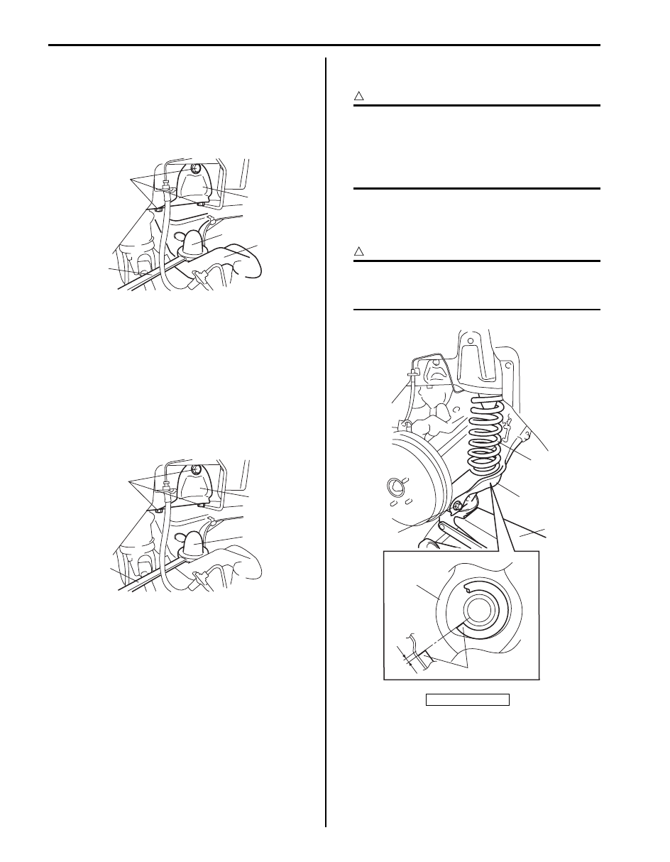
9) Remove bump stopper (1) from suspension upper 

arm (2) by using special tool (A).

Special tool
(A):  09941–66010

10) Remove bump stopper upper seat bolts (4), and 

bump stopper upper seat (3) from body.

Installation

1) Install bump stopper upper seat (1) to body and 

tighten bolts (2).

2) Tighten bump stopper (3) to specified torque by 

using special tool (A).

Special tool
(A):  09941–66010

Tightening torque
Bump stopper (a):  50 N·m (5.0 kgf-m, 36.5 lb-ft)

3) Installing coil spring on lower arm and place coil 

spring end (1) onto lower arm (2) as shown.

CAUTION

!


• Flat end coil spring is upward.
• Upper end of coil spring has to be firmly 

mated to coil spring rubber seat.

• End of coil spring must not interfere with 

step of spring lower seat.


4) Support lower arm (2) with jack (4).
5) Hoist jack and then install lower arm outer bolt (5) 

and tighten bolt temporarily by hand.

CAUTION

!


If lower arm outer bolt is reused, apply 
engine oil to thread, bearing and trunk 
surface.


4

3

1

2

(A)

I5JB0A230013-01

2

1

3

(A)

I5JB0A230014-01

“a”: 5 mm

1

2

5

3

4

2

“a”

I5JB0D230001-02

Rear Suspension:  2C-8

6) With marks (1) on lower arm washer (2) and rear 

suspension frame (3) marked before remove aligned 
to each other, tighten lower arm mount nut (4) 
temporarily by hand.

7) Install rear shock absorber referring to “Rear Shock 

Absorber Removal and Installation”.

8) Connect rear height sensor link (if equipped) to lower 

arm for left side referring to “Height Sensor Removal 
and Installation (If Equipped) in Section 9B”.

9) Install wheel with nuts and lower vehicle.

10) Tighten wheel nuts to specified torque.

Tightening torque
Wheel nut:  100 N·m (10.0 kgf-m, 72.5 lb-ft)

11) Tighten lower arm outer bolt and lower arm mount 

nut, shock absorber bolts to specified torque with 
vehicle weight on suspension.

CAUTION

!


• It is the most desirable to have vehicle off 

hoist and in non-loaded condition when 
tightening them.

• Tighten Lower arm washer with match 

marks aligned.


Tightening torque
Lower arm outer bolt:  135 N·m (13.5 kgf-m, 98.0 
lb-ft)
Lower arm mount nut:  135 N·m (13.5 kgf-m, 98.0 
lb-ft)
Shock absorber lower bolt:  90 N·m (9.0 kgf-m, 
65.0 lb-ft)

12) Check rear toe and camber adjust it as necessary. 

For check and adjustment procedures, refer to “Rear 
Wheel Alignment Inspection and Adjustment”.

13) Adjust headlight auto leveling system, refer to 

“Initialization of Auto Leveling Headlight System in 
Section 9B”
.

Rear Coil Spring Check

S6JB0A2306006

• Inspect for cracks, deformation or damage. If any, 

replace defective part.

1

2

3

3

4

4

I5JB0A230010-01

I5JB0A230016-01

2C-9 Rear Suspension: 

Rod and Arm Components

S6JB0A2306007

1

5

2

21

18

16

6

8

11

9

13

(a)

3

(a)

(a)

3

12

(a)

19

(a)

17

20

(c)

(b)

4

(a)

7

(a)

15

(a)

10

14

F

I6JB0A230003-01

1. Upper arm

10. Lower arm mount nut

: If reuse nut, apply engine oil to thread and 
bearing.

19. Trailing rod mount nut

: If reuse nut, apply engine oil to 
thread and bearing.

2. Upper arm bolt

11. Control rod

20. Trailing rod mount bracket bolt

3. Upper arm mount nut

: If reuse nut, apply engine oil to thread and 
bearing.

12. Control rod outer bolt

: If reuse bolt, apply engine oil to thread, 
bearing and trunk surface.

21. Trailing rod mount bracket

4. Upper arm joint nut

13. Control rod inner bolt

F: Forward

5. Rear suspension knuckle

14. Control rod washer

: 135 N

⋅m (13.5 kgf-m, 98.0 lb-ft)

6. Lower arm

15. Control rod mount nut

: If reuse nut, apply engine oil to thread and 
bearing.

: 55 N

⋅m (5.5 kgf-m, 40.0 lb-ft)

7. Lower arm outer bolt

: If reuse bolt, apply engine oil to thread, 
bearing and trunk surface.

16. Trailing rod

: 105 N

⋅m (10.5 kgf-m, 76.0 lb-ft)

8. Lower arm inner bolt

17. Trailing rod rear bolt

: If reuse bolt, apply engine oil to thread, 
bearing and trunk surface.

: Do not reuse.

9. Lower arm washer

18. Trailing rod front bolt

Rear Suspension:  2C-10

Control Rod Removal and Installation

S6JB0A2306008

Removal

1) Hoist vehicle and remove rear wheels.
2) Support lower arm with jack.
3) Remove parking cable hanger bolt (1).

4) Put match marks (1) on control rod washer (2) and 

on suspension frame (3) to install the bolts correctly 
in position.

5) Remove control rod inner bolt (4) and control rod 

outer bolt (5) and then control rod (6).

Installation

1) Install control rod (1).

a) Install control rod (1) to rear suspension frame.
b) Insert control rod inner bolt (2) from the vehicle 

frontward.

c) Install control rod washer (3) with its graduated 

part facing up.

d) Insert control rod outer bolt (4).

CAUTION

!


If control rod outer bolt and control rod 
mount nut are reused, apply engine oil to 
thread, bearing and trunk surface.


e) The marks (5) on control rod washer (3) and rear 

suspension frame marked before its removal 
must be aligned and, tighten bolt and nut 
temporarily by hand.

1

I5JB0A230019-01

4

6

5

1

3

2

I5JB0A230020-01

[A]: Correct

U: Upper side

[B]: Wrong

L: Lower side

4

2

1

3

[A]

[B]

3

5

U

L

I5JB0A230021-02


Content   ..  219  220  221  222   ..