Suzuki Grand Vitara JB416 / JB420 / JB419. Service manual - part 220
 

  Index      Suzuki     Suzuki Grand Vitara JB416 / JB420 / JB419 - service and repair manual 2007 year


Search            copyright infringement  


Content   ..  218  219  220  221   ..


Suzuki Grand Vitara JB416 / JB420 / JB419. Service manual - part 220


2C-3 Rear Suspension: 

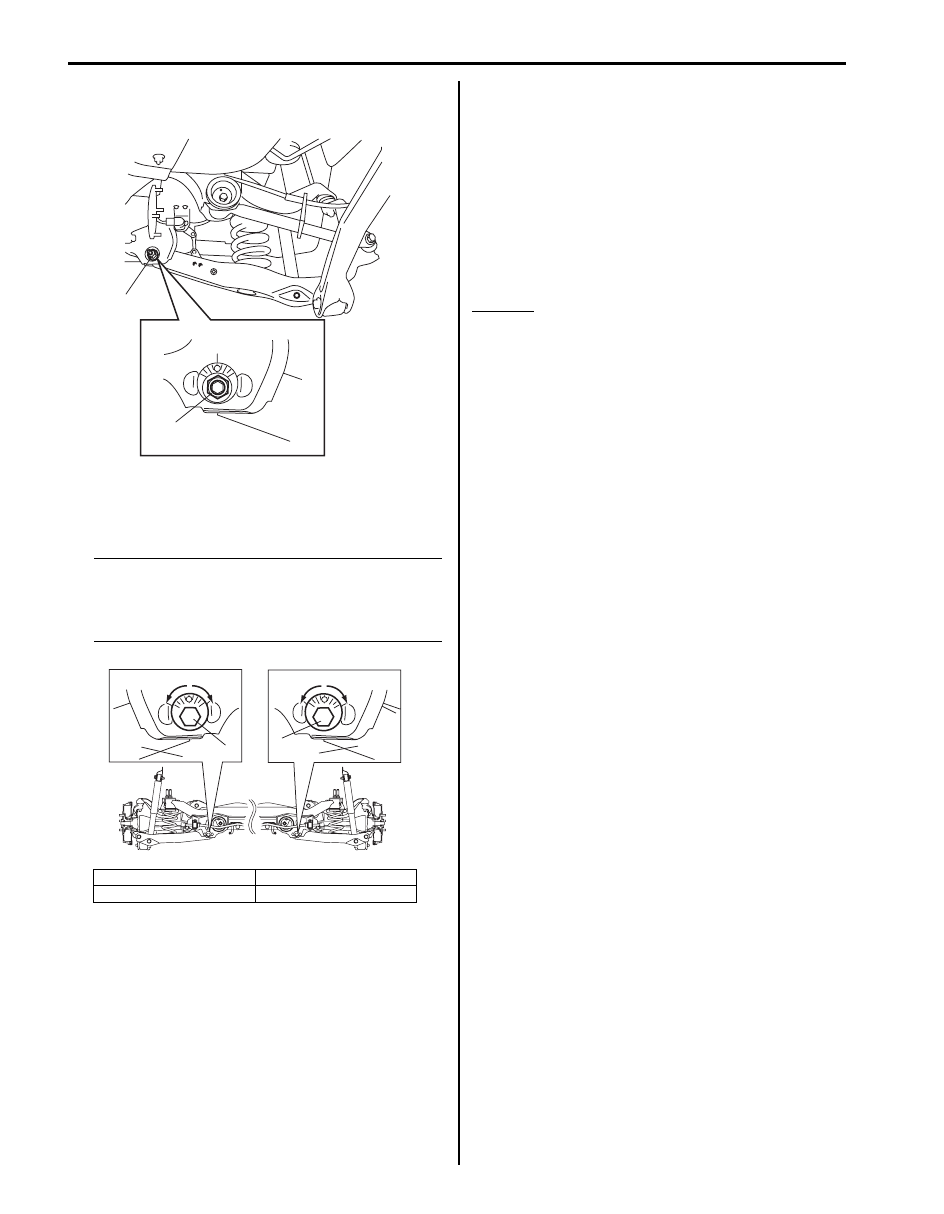
Lower arm adjustment

1) Loosen right and left lower arm mount nuts (1).

2) Adjust toe and camber to satisfy the specification by 

turning right and left lower arm inner bolts (cam 
bolts) (1) with same amount.

NOTE
When bolt is turned a-direction, camber 
becomes “+” and toe becomes “OUT”. When 
bolt is turned b-direction, camber becomes 
“–” and toe becomes “IN”.


3) After adjustment, tighten right and left nuts to 

specified torque while holding cam bolt with another 
wrench to prevent it from turning.

Tightening torque
Lower arm mount nut:  135 N·m (13.5 kgf-m, 98.0 
lb-ft)

Reference Information
Side slip
When checked with side slip tester, side slip should 
satisfy following specification.

Side slip
IN 7.5 mm/m (IN 0.2953 in/3.3 ft)
If side slip is greatly different, toe and/or camber 
may be correct.

[A]: Left side

2. Lower arm

[B]: Right side

1

1

I5JB0A230004-01

[A]

[B]

a

a

b

b

1

2

1

2

I5JB0A230005-01

Rear Suspension:  2C-4

Rear Shock Absorber and Rear Coil Spring Components

S6JB0A2306002

13

11

12

3

2

9

8

4

1

(b)

(b)

10

7

F

14

(a)

5

(c)

6

(d)

I6JB0A230002-01

1. Rear shock absorber

8. Lower arm inner bolt

F: Forward

2. Rear coil spring

9. Lower arm washer

: 60 N

⋅m (6.0 kgf-m, 43.5 lb-ft)

3. Coil spring rubber seat

10. Lower arm mount nut

: If reuse nut, apply engine oil to thread 
and bearing.

: 135 N

⋅m (13.5 kgf-m, 98.0 lb-ft)

4. Lower arm

11. Upper arm

: 90 N

⋅m (9.0 kgf-m, 65.0 lb-ft)

5. Shock absorber upper bolt

: If reuse bolt, apply engine oil to thread, bearing and 
trunk surface.

12. Bump stopper

: 50 N

⋅m (5.0 kgf-m, 36.5 lb-ft)

6. Shock absorber lower bolt

: If reuse bolt, apply engine oil to thread, bearing and 
trunk surface.

13. Bump stopper upper seat

7. Lower arm outer bolt

: If reuse bolt, apply engine oil to thread, bearing and 
trunk surface.

14. Bump stopper upper seat bolt

2C-5 Rear Suspension: 

Rear Shock Absorber Removal and Installation

S6JB0A2306003

Removal

1) Hoist vehicle, allowing rear suspension to hang free.
2) Remove wheel.
3) Support lower arm (1) with jack (2) and remove 

shock absorber bolts (3).

4) Compress the shock absorber enough to remove it 

from body.

Installation
Install shock absorber by reversing removal procedure, 
noting the following instructions.
• Tighten all fasteners to specified torque.

Tightening torque
Shock absorber upper bolt (a):  60 N·m (6.0 kgf-m, 
43.5 lb-ft)
Shock absorber lower bolt (b):  90 N·m (9.0 kgf-m, 
65.0 lb-ft)
Wheel nut:  100 N·m (10.0 kgf-m, 72.5 lb-ft)

CAUTION

!


• If shock absorber bolts are reused, apply 

engine oil to thread, bearing and trunk 
surface.

• It is the most desirable to have vehicle off 

hoist and in non-loaded condition when 
tightening them.


1

2

3

3

I5JB0A230007-01

I5JB0A230008-01

(a)

(b)

I5JB0A230081-01

Rear Suspension:  2C-6

Shock Absorber Check

S6JB0A2306004

• Inspect for deformation or damage.
• Inspect bushings for wear or damage.
• Inspect for evidence of oil leakage.
Replace any defective part.

WARNING

!


When handling rear shock absorber (1) in 
which high-pressure gas is sealed, make 
sure to observe the following precautions.
• Don’t disassemble it.
• Don’t put it into the fire.
• Don’t store it where it gets hot.
• Before disposing it, be sure to drill a hole 

in it where shown by an arrow in the figure 
and let gas and oil out. Lay it down 
sideways for this work.

• The gas itself is harmless but it may issue 

out of the hole together with chips 
generated by the drill. Therefore, be sure 
to wear goggle.


Drill hole diameter
“a”: Approx. 3 mm (0.12 in.)

Rear Coil Spring and Bump Stopper Removal 
and Installation

S6JB0A2306005

Removal

1) Hoist vehicle, allowing rear suspension to hang free.
2) Remove rear wheels.
3) Disconnect rear height sensor link (if equipped) from 

lower arm for left side referring to “Height Sensor 
Removal and Installation (If Equipped) in Section 
9B”
.

4) Remove rear shock absorber referring to “Rear 

Shock Absorber Removal and Installation”.

5) Put match marks (1) on lower arm washer (2) and on 

suspension frame (3) to install the bolts correctly in 
position.

6) Loosen lower arm mount nut (4).

7) Remove lower arm outer bolt (1).
8) Lower jack and then remove rear coil spring (2) and 

coil spring rubber seat (3).

I5JB0A230011-01

1

2

3

3

4

4

I5JB0A230010-01

3

2

1

I5JB0A230012-01


Content   ..  218  219  220  221   ..