Suzuki Grand Vitara JB416 / JB420 / JB419. Service manual - part 224
 

  Index      Suzuki     Suzuki Grand Vitara JB416 / JB420 / JB419 - service and repair manual 2007 year


Search            copyright infringement  


Content   ..  222  223  224  225   ..


Suzuki Grand Vitara JB416 / JB420 / JB419. Service manual - part 224


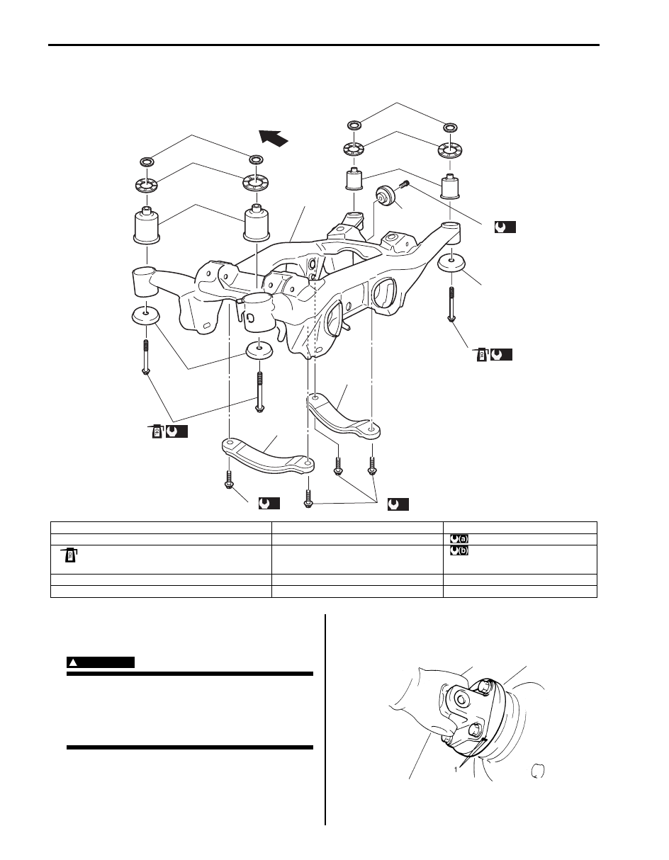
2C-19 Rear Suspension: 

Rear Suspension Frame Components

S6JB0A2306020

Rear Suspension Frame Removal and 
Installation

S6JB0A2306021

WARNING

!


When removing rear suspension frame, be 
sure to apply some supporting equipment 
(such as mission jack) under it at well-
balanced position in the center section so as 
to prevent from its drop.


Removal

1) Hoist vehicle and remove rear wheels.
2) Remove muffler and exhaust center pipe referring to 

“Exhaust System Components: For Petrol Engine 
Model in Section 1K”.

3) To facilitate reinstallation, put match marks (1) on 

rear propeller shaft flange and differential flange. 
Disconnect rear propeller shaft form differential.

F

3

2

(a)

(b)

(b)

(b)

1

3

4

5

4

5

6

6

7

8

8

2

(a)

10

9

9

I6JB0A230005-01

F: Forward

5. Upper mount stopper washer

10. Dynamic damper bolt

1. Rear suspension frame

6. Rear suspension frame busing

: 135 N

⋅m (13.5 kgf-m, 98.0 lb-ft)

2. Rear suspension frame mount bolt

: If reuse bolt, apply engine oil to thread, bearing and 
trunk surface.

7. Dynamic damper

: 50 N

⋅m (5.0 kgf-m, 36.5 lb-ft)

3. Rear suspension frame mount washer

8. Stiffener

4. Rear suspension frame mount stopper

9. Rear suspension frame stiffener bolt

I3RH01232006-01

Rear Suspension:  2C-20

4) Remove rear wheel hub assembly referring to “Rear 

Wheel Hub Assembly Removal and Installation”.

5) Remove control rod referring to “Control Rod 

Removal and Installation”.

6) Remove trailing rod referring to “Trailing Rod 

Removal and Installation”.

7) Remove lower arm referring to “Lower Arm Removal 

and Installation”.

8) Remove rear drive shaft referring to “Rear Drive 

Shaft Assembly Removal and Installation: Rear in 
Section 3A”
.

9) Remove rear suspension knuckle referring to “Rear 

Suspension Knuckle Removal and Installation”.

10) Remove upper arm referring to “Upper Arm Removal 

and Installation”.

11) Remove parking cable clamp bolt (1) and parking 

cable clamp (2).

12) Remove rear wheel speed sensor clamp bolt (1) and 

speed sensor harness clamp (2) (if equipped).

13) Disconnect rear height sensor connector (3) and 

rear height sensor harness clamp (4) (if equipped) 
for left side.

14) Support rear suspension frame with rear differential 

by using mission jack (1).

15) Remove rear suspension frame mount bolts (1) and 

washer (2) and then lower mission jack and remove 
rear suspension frame (3) with rear differential and 
rear suspension frame stopper (4).

16) Dismounting rear differential from rear suspension 

frame referring to “Rear Differential Unit 
Components: Rear in Section 3B”.

17) Remove rear suspension frame stiffener and 

dynamic damper from rear suspension frame, if 
necessary.

2

1

I5JB0A230047-01

4

3

4

1

4

2

I5JB0A230048-01

1

I5JB0A230049-01

2

2

3

1

1

I5JB0A230050-03

2C-21 Rear Suspension: 

Installation

1) Install rear suspension frame stiffeners (1) and 

dynamic damper (2) to rear suspension frame (3), if 
removed.

Tightening torque
Rear suspension frame stiffener bolt (a):  50 N·m 
(5.0 kgf-m, 36.5 lb-ft)
Dynamic damper bolt (b):  50 N·m (5.0 kgf-m, 
36.5 lb-ft)

2) Remounting rear differential to rear suspension fame 

referring to “Rear Differential Unit Components: Rear 
in Section 3B”.

3) Support rear suspension frame with rear differential 

by using mission jack, and jack up it.

4) Install rear suspension frame (3) to vehicle body and 

tighten rear suspension frame mount bolts (1) with 
washer (2) to specified torque.

CAUTION

!


If suspension frame mount bolts are reused, 
apply engine oil to thread, bearing and trunk 
surface.


Tightening torque
Rear suspension frame mount bolt (a):  135 N·m 
(13.5 kgf-m, 98.0 lb-ft)

5) Connect rear height sensor connector (3) and rear 

height sensor harness clamp (4) (if equipped) for left 
side.

6) Tighten wheel sensor bolt (1) to specified torque and 

then connect wheel speed sensor harness clamp 
(2).

Tightening torque
Wheel speed sensor clamp bolt (a):  11 N·m (1.1 
kgf-m, 8.0 lb-ft)

7) Tighten parking cable clamp bolt (1) to specified 

torque and then connect parking cable clamp (2).

Tightening torque
Parking cable clamp bolt (a):  25 N·m (2.5 kgf-m, 
18.0 lb-ft)

8) Install upper arm referring to “Upper Arm Removal 

and Installation”.

9) Install rear suspension knuckle referring to “Rear 

Suspension Knuckle Removal and Installation”.

10) Install rear drive shaft referring to “Rear Drive Shaft 

Assembly Removal and Installation: Rear in Section 
3A”.

11) Install lower arm referring to “Lower Arm Removal 

and Installation”.

3

2

(b)

1

1

(a)

I6JB0A230006-01

2

2

3

1,(a)

1,(a)

I5JB0A230051-02

4

3

4

4

2

1,(a)

I5JB0A230052-01

2

1,(a)

I5JB0A230053-01

Rear Suspension:  2C-22

12) Install trailing rod referring to “Trailing Rod Removal 

and Installation”.

13) Install control rod referring to “Control Rod Removal 

and Installation”“Control Rod Removal and 
Installation”.

14) Install rear wheel hub assembly referring to “Rear 

Wheel Hub Assembly Removal and Installation”.

15) Connect rear propeller shaft to differential aligning 

match marks on flanges. Tighten bolts and nuts to 
specified torque. Refer to “Propeller Shaft Removal 
and Installation in Section 3D”.

16) Install exhaust muffler and exhaust center pipe 

referring to “Exhaust System Components: For 
Petrol Engine Model in Section 1K”
.

17) Fill reservoir with brake fluid and bleed brake 

system. Refer to “Air Bleeding of Brake System in 
Section 4A”
.

18) Upon completion of all jobs, depress brake pedal 

with about 30 kg (66 lbs) load a few times so as to 
obtain proper drum-to-shoe clearance. Adjust 
parking brake cable. Refer to “Parking Brake Check 
and Adjustment in Section 4D”.

19) Install rear wheels.
20) Check to ensure that brake drum is free from 

dragging and proper braking is obtained.

21) Lower hoist and tighten rear wheel bolts to specified 

torque.

Tightening torque
Wheel nut:  100 N·m (10.0 kgf-m, 72.5 lb-ft)

22) Bounce vehicle up and down to stabilize suspension.
23) Tighten each bolts and nuts to specified torque with 

vehicle weight on suspension. 

NOTE
It is the most desirable to have vehicle off 
hoist and in non-loaded condition when 
tightening them.


24) Perform brake test (foot brake and parking brake).
25) Check each installed part for fluid leakage.
26) Check rear toe and camber and adjust it if 

necessary. For check and adjustment procedures, 
refer to “Rear Wheel Alignment Inspection and 
Adjustment”.

27) Adjust auto leveling headlight system, referring to 

“Initialization of Auto Leveling Headlight System in 
Section 9B”
.

Rear Suspension frame / Bushing Disassembly 
and Assembly

S6JB0A2306022

Disassembly

1) Cut rubber (1) of flange of rear suspension frame 

bushing.

2) Using grinder (2), grind off flange (3) of upper arm 

bushing.

CAUTION

!


Be careful not to damage rear suspension 
frame bushing (4) when grinding flange (3) of 
upper arm bushing with grinder.


3) Push out rear suspension frame bushing by using 

hydraulic press (1) and special tool.

Special tool
(A):  09913–75520

I5JB0A230054-02

1

(A)

I5JB0A230055-02


Content   ..  222  223  224  225   ..