Suzuki Grand Vitara JB416 / JB420 / JB419. Service manual - part 153
 

  Index      Suzuki     Suzuki Grand Vitara JB416 / JB420 / JB419 - service and repair manual 2007 year


Search            copyright infringement  


Content   ..  151  152  153  154   ..


Suzuki Grand Vitara JB416 / JB420 / JB419. Service manual - part 153


1D-138 Engine Mechanical: For F9Q Engine

Intercooler Removal and Installation

S6JB0A1436046

Removal 

1) Remove front bumper referring to “Front Bumper 

Components in Section 9K”.

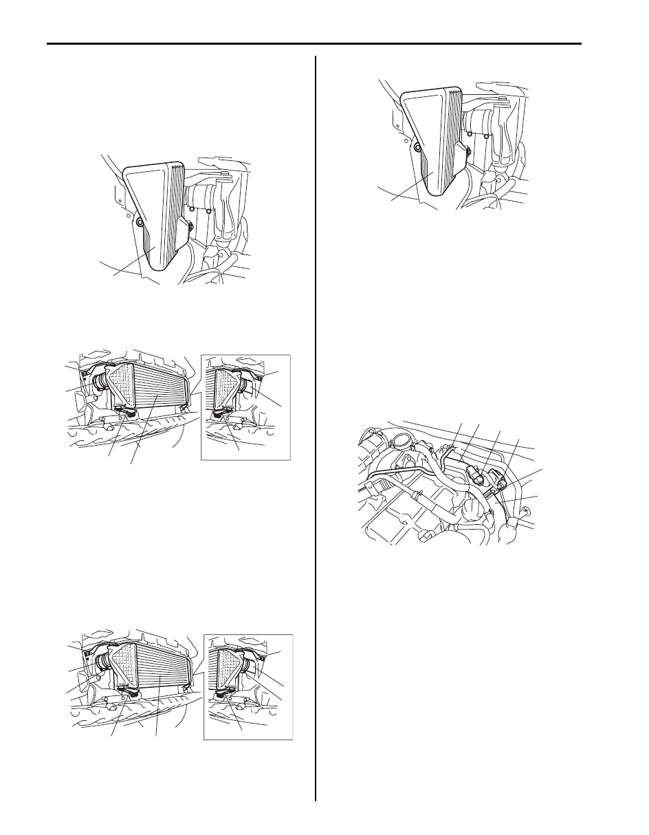
2) Remove resonator (1).

3) Disconnect intercooler inlet hose (1) and outlet hose 

(2) from intercooler (4).

4) Remove intercooler brackets (3) and intercooler (4).

Installation

1) Install intercooler brackets (1) and intercooler (2).
2) Connect intercooler inlet hose (3) and outlet hose 

(4).

Tightening torque
Intercooler inlet hose clamp (a):  4.5 N·m (0.45 
kgf-m, 3.5 lb-ft)
Intercooler outlet hose clamp (b):  4.5 N·m (0.45 
kgf-m, 3.5 lb-ft)

3) Install resonator (1).

4) Install front bumper referring to “Front Bumper 

Components in Section 9K”.

Air intake Pipe Removal and Installation

S6JB0A1436074

Removal

1) Disconnect negative (–) cable at battery.
2) Disconnect boost presser sensor connector (1) and 

intake throttle valve connector (2).

3) Disconnect intercooler outlet pipe (3) from air intake 

pipe (5) after removing intercooler outlet pipe clamp 
(6).

4) Remove vacuum pipe (4) and air intake pipe.

Installation
Reverse removal procedure for installation noting the 
following.
• Tighten air intake pipe bolt and nut to specified torque.

Tightening torque
Air intake pipe bolt and nut:  21 N·m (2.1 kgf-m, 
15.5 lb-ft)

• Tighten intercooler outlet pipe clamp to specified 

torque as follows.
a. Tighten intercooler outlet pipe clamp to 5 N

⋅m (0.5 

kgf-m, 4.0 lb-ft).

b. Wait 5 minutes.
c. Retighten intercooler outlet pipe clamp to 5 N

⋅m 

(0.5 kgf-m, 4.0 lb-ft).

1

I5JB0B140007-01

3

1

3

4

3

2

3

I5JB0B140008-01

1

3

1

2

1

4

1

(a)

(b)

I5JB0B140009-02

1

I5JB0B140007-01

4

1

2

3

5

6

I6JB0A143001-01

Engine Mechanical: For F9Q Engine 1D-139

Tightening torque
Intercooler outlet pipe clamp:  Tighten 5 N

m (0.5 

kgf-m, 4.0 lb-ft) and 5 N

m (0.5 kgf-m, 4.0 lb-ft) after 5 

minutes

Cylinder Head Cover Components

S6JB0A1436047

Cylinder Head Cover Removal and Installation

S6JB0A1436048

Removal

1) Disconnect CMP sensor connector (1).

2) Remove harness bracket and timing belt cover No.2 

(1).

3) Remove air intake pipe (1) referring to “Air intake 

Pipe Removal and Installation: For F9Q Engine”.

4) Disconnect ventilation hose No.2 (2) from ventilation 

pipe No.2 (3).

5) Disconnect ventilation hose No.3 (4) from oil vapor 

recirculation valve (5).

6) Remove fuel injector cover (6).

1. Cylinder head cover

3. Cylinder head cover gasket

: Do not reuse.

2. Cylinder head cover bolt gasket

: Tighten 12 N

⋅m (1.2 kgf-m, 9.0 lb-ft) by the specified procedure.

1

(a)

2

3

I5JB0B140010-01

1

I5JB0B140011-01

1

I5JB0B140012-01

5

2

3

1

6

4

I6JB0A143002-01

1D-140 Engine Mechanical: For F9Q Engine

7) Remove cylinder head cover bolts evenly and 

gradually in numerical order (“1” through “3”) as 
shown in figure.

8) Remove cylinder head cover (1), cylinder head cover 

gasket (2) and cylinder head cover bolt gaskets (3).

Installation

1) Remove oil and dust from sealing surfaces on 

cylinder head and cylinder head cover.

2) Install cylinder head cover (1), new cylinder head 

cover gasket (2) and new cylinder head cover bolt 
gaskets (3).

3) Tighten cylinder head cover bolts evenly and 

gradually in numerical order (“1” through “3”) by 
repeating tightening sequence two or three times 
until specified torque is obtained.

Tightening torque
Cylinder head cover bolt (a):  Tighten 12 N

m (1.2 

kgf-m, 9.0 lb-ft) by the specified procedure

4) Install fuel injector cover (1).

Tightening torque
Injector cover bolt (a):  8 N·m (0.8 kgf-m, 6.0 lb-ft)

5) Connect ventilation hose No.2 (2) to ventilation pipe 

No.2 (3).

6) Connect ventilation hose No.3 (4) to oil vapor 

recirculation valve (5).

7) Install air intake pipe (6) referring to “Air intake Pipe 

Removal and Installation: For F9Q Engine”.

8) Connect CMP sensor connector (1).

I5JB0B140014-01

I5JB0B140015-01

I5JB0B140015-01

I5JB0B140016-02

5

2

3

(a)

6

1

4

I6JB0A143003-01

1

I5JB0B140011-01

Engine Mechanical: For F9Q Engine 1D-141

9) Install timing belt cover No.2 (1) and harness 

bracket.

Tightening torque
Timing belt cover No.2 bolt (a):  55 N·m (5.5 kgf-
m, 40.0 lb-ft)

Oil Separator Components

S6JB0A1436075

(a)

1

I5JB0B140018-01

6

7

(b)

9

10

(a)

3

2

4

1

8

5

(a)

(c)

(d)

I5JB0B140145-02

1. Ventilation hose No.2

6. Ventilation hose No.1

: 25 N

⋅m (2.5 kgf-m, 18.5 lb-ft)

2. Oil separator return hose

7. Ventilation pipe No.1

: 10 N

⋅m (1.0 kgf-m, 7.5 lb-ft)

3. Flesh air vent hose

8. Oil level gauge

: 8 N

⋅m (0.8 kgf-m, 6.0 lb-ft)

4. Oil separator

9. O-ring

: 5 N

⋅m (0.5 kgf-m, 4.0 lb-ft)

5. Ventilation pipe No.2

10. Ventilation hose No.3 union bolt

: Do not reuse.


Content   ..  151  152  153  154   ..