Suzuki Grand Vitara JB416 / JB420 / JB419. Service manual - part 152
 

  Index      Suzuki     Suzuki Grand Vitara JB416 / JB420 / JB419 - service and repair manual 2007 year


Search            copyright infringement  


Content   ..  150  151  152  153   ..


Suzuki Grand Vitara JB416 / JB420 / JB419. Service manual - part 152


1D-134 Engine Mechanical: For F9Q Engine

9) Crank engine with fully charged battery, and read the 

highest pressure on compression gauge.

NOTE

• For measuring compression pressure, 

crank engine at least 250 r/min. by using 
fully charged battery.

• If measured compression pressure is 

lower than limit value, check installation 
condition of special tool. If it is properly 
installed, possibility is compression 
pressure leakage from where piston ring or 
valve contact.


Compression pressure
Standard:
2200 – 2600 kPa (22 – 26kgf/cm

2

, 319 – 392psi)

Limit:
Min. 2100 kPa (21 kgf/cm

2

, 304.5 psi)

Max. 2700 kPa (27 kgf/cm

2

, 391.5 psi)

Max. difference between any two cylinders:
400 kPa (4 kgf/cm

2

, 58 psi)

10) Carry out Steps 7) through 9) on each cylinder to 

obtain 4 readings.

11) Disconnect negative (–) cable at battery.

12) After checking, install glow plugs referring to “Glow 

Plug Removal and Installation: For Diesel Engine 
Model in Section 1C”.

13) Connect ECM connectors and pre-heating unit 

connector.

14) Connect negative (–) cable at battery.

Valve Lash (Clearance) Inspection

S6JB0A1434003

1) Remove negative cable at battery.
2) Remove cylinder head cover referring to “Cylinder 

Head Cover Removal and Installation: For F9Q 
Engine”.

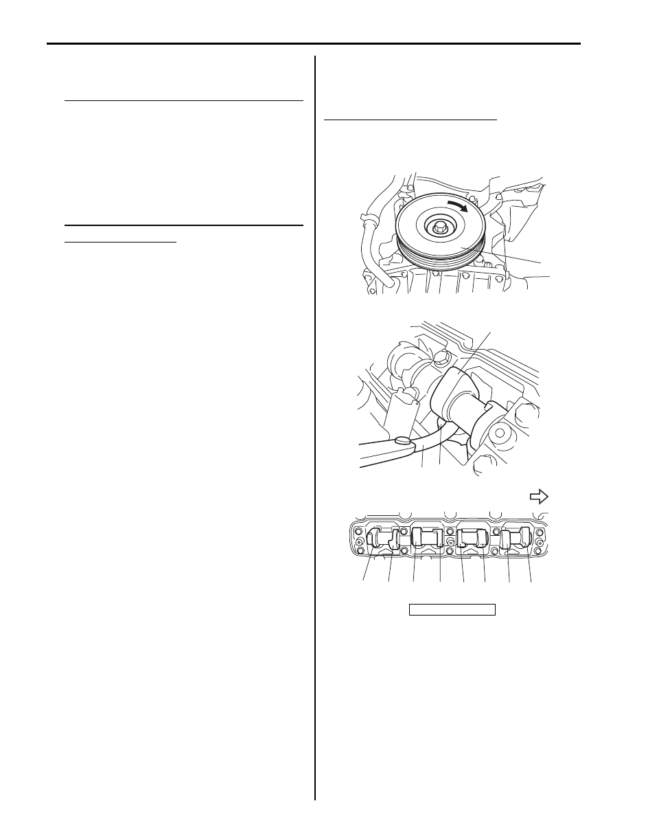
3) Turn crankshaft pulley (1) clockwise until cam lobe 

(2) becomes perpendicular to tappet face (3) at 
valves “1” and “6” as shown in figure.

4) Check valve lashes with thickness gauge (4) 

according to the following procedure.
a) Check valve lashes at valves “1” and “6”.
b) Turn camshaft by 90

° by turning crankshaft 

pulley with wrench.

c) Make sure that cam lobe is perpendicular to 

tappet face at valves to be checked (in this case, 
“5” and “8”), if not, adjust camshaft position by 
turning crankshaft pulley. Check valve lashes.

d) In the same manner as b) – c), check valve 

lashes at valves “4” and “7”.

e) In the same manner as b) – c) again, check 

valve lashes at valves “2” and “3”.

If valve lash (clearance) is out of specification, 
record valve lash (clearance) and adjust it to 
specification referring to “Valve Lash (Clearance) 
Adjustment: For F9Q Engine”
.

Valve lash (clearance) specification
When cold:

• Intake: 0.15 – 0.25 mm (0.0060 – 0.0098 in.)
• Exhaust: 0.35 – 0.45 mm (0.0138 – 0.0177 in.)

5. Fly wheel side

2

4

3

“8”

“7”

“6”

“5”

“4”

“3”

“2”

“1”

1

5

I5JB0B140003-03

Engine Mechanical: For F9Q Engine 1D-135

Valve Lash (Clearance) Adjustment

S6JB0A1434004

1) Measure valve lash (clearance) referring to “Valve 

Lash (Clearance) Inspection: For F9Q Engine”.

2) Remove tappet referring to “Camshaft and Tappet 

Removal and Installation: For F9Q Engine”.

3) Using dial gauge (1), magnetic stand (2) and surface 

plate (3), measure thickness of removed tappet.

4) Determine replacement tappet by calculating 

thickness of new tappet with the following formula.
Intake side:
A = B + C – 0.200 mm (0.00787 in.)
Exhaust side:
A = B + C – 0.400 mm (0.01575 in.)
A: Thickness of new tappet
B: Thickness of removed tappet
C: Measured valve lash (clearance)
Example of intake side:
When thickness of removed tappet is 7.825 mm 
(0.30807 in.), and measured valve lash (clearance) 
is 0.275 mm (0.0108 in.):
A = 7.825 mm (0.30807 in.) + 0.275 mm (0.0108 in.) 
– 0.200 mm (0.007382 in.) = 7.900 mm (0.31102 in.)
Calculated thickness of new tappet = 7.900 mm 
(0.31102 in.)

5) Select new tappet with a thickness as close as 

possible to calculated value.

Available new tappet

6) Install tappet and camshaft referring to “Camshaft 

and Tappet Removal and Installation: For F9Q 
Engine”.

7) Confirm valve lash (clearance) is within specification 

referring to “Valve Lash (Clearance) Inspection: For 
F9Q Engine”.

8) Install cylinder head cover referring to “Cylinder 

Head Cover Removal and Installation: For F9Q 
Engine”.

4. Tappet

I5JB0B140004-01

Thickness

mm (in.)

7.550 (0.29724)

7.875 (0.31004)

7.575 (0.29823)

7.900 (0.31102)

7.600 (0.29921)

7.925 (0.31201)

7.625 (0.30020)

7.950 (0.31299)

7.650 (0.30118)

7.975 (0.31398)

7.675 (0.30217)

8.000 (0.31496)

7.700 (0.30315)

8.025 (0.31595)

7.725 (0.30413)

8.050 (0.31693)

7.750 (0.30512)

8.075 (0.31791)

7.775 (0.30610)

8.100 (0.31890)

7.800 (0.30709)

8.125 (0.31988)

7.825 (0.30807)

8.150 (0.32087)

7.850 (0.30906)

1D-136 Engine Mechanical: For F9Q Engine

Repair Instructions

Air Cleaner Components

S6JB0A1436072

Air Cleaner Removal and Installation

S6JB0A1436073

Removal

1) Disconnect negative (–) cable at battery.
2) Disconnect MAF sensor connector.
3) Remove air cleaner.

Installation
Reverse removal procedure for installation.

Air Cleaner Filter Removal and Installation

S6JB0A1436001

Removal

1) Open air cleaner case (1) by unhooking its clamps 

(2).

2) Remove air cleaner filter from case.

Installation
Reverse removal procedure for installation.

1. MAF sensor

3. Air cleaner filter

5. Gasket

2. Air cleaner upper case

4. Air cleaner lower case

: 6 N

⋅m (0.6 kgf-m, 4.5 lb-ft)

2

5

1

3

4

(a)

I5JB0B140143-01

2

2

1

I5JB0B140005-01

Engine Mechanical: For F9Q Engine 1D-137

Air Cleaner Filter Inspection and Cleaning

S6JB0A1436002

Inspection
Check air cleaner filter for dirt. Replace excessive dirty 
filter.

Cleaning
Blow off dust by compressed air from air outlet side of 
filter.

Intercooler and Air Intake Pipe Components

S6JB0A1436045

I2RH0B140150-01

5

5

5

4

1

3

2

5

6

7

(a)

(d)

(b)

(b)

(b)

(c)

9

8

(b)

I5JB0B140006-04

1. Intercooler

6. Intercooler outlet hose

: 4.5 N

⋅m (0.45 kgf-m, 3.5 lb-ft)

2. Turbocharger outlet hose

7. Intercooler outlet pipe

: 21 N

⋅m (2.1 kgf-m, 15.5 lb-ft)

3. Intercooler inlet pipe

8. Air intake pipe

: Tighten 5 N

⋅m (0.5 kgf-m, 4.0 lb-ft) 

and 5 N

⋅m (0.5 kgf-m, 4.0 lb-ft) after 

5 minutes.

4. Intercooler inlet hose

9. EGR valve

5. Intercooler bracket

: 5 N

⋅m (0.5 kgf-m, 4.0 lb-ft)


Content   ..  150  151  152  153   ..