Suzuki Grand Vitara JB416 / JB420 / JB419. Service manual - part 131
 

  Index      Suzuki     Suzuki Grand Vitara JB416 / JB420 / JB419 - service and repair manual 2007 year


Search            copyright infringement  


Content   ..  129  130  131  132   ..


Suzuki Grand Vitara JB416 / JB420 / JB419. Service manual - part 131


1D-50 Engine Mechanical: For M16A Engine with VVT

2) Next, check crankshaft pin diameter. On crank web 

No.3, four alphabets are stamped as shown in the 
figure.
Three kinds of alphabet (“A”, “B” and “C”) represent 
the following crankshaft pin diameter respectively.
For example, stamped “A” indicates that 
corresponding crankshaft pin diameter is 41.994 – 
42.000 mm (1.6533 – 1.6534 in.).

Crankshaft pin outer diameter

3) There are five kinds of standard bearings differing in 

thickness. To distinguish them, they are painted in 
the following colors at the position as indicated in the 
figure.
Each color indicated the following thickness at the 
center of bearing.

Standard size of connecting rod bearing 
thickness

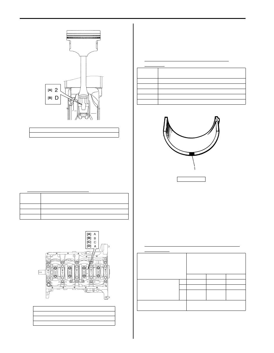
4) From number stamped on connecting rod and its cap 

and alphabets stamped on crank web No.3, 
determine new standard bearing to be installed to 
connecting rod big end inside, by referring to the 
table.
For example, if number stamped on connecting rod 
and its cap is “1” and alphabet stamped on crank 
web No.3 is “B”, install a new standard bearing 
painted in “Black” to its connecting rod big end 
inside.

Specification of new standard connecting rod 
bearing size

[A]: Connecting rod big end inside diameter number
[B]: Weight indication mark

Stamped 

alphabet

Crankshaft pin diameter

A

41.9940 – 42.0000 mm (1.6533 – 1.6534 in.)

B

41.9880 – 41.9939 mm (1.6531 – 1.6532 in.)

C

41.9820 – 41.9879 mm (1.6529 – 1.6530 in.)

[A]: Crankshaft pin diameter for No.1 cylinder
[B]: Crankshaft pin diameter for No.2 cylinder

[C]: Crankshaft pin diameter for No.3 cylinder
[D]: Crankshaft pin diameter for No.4 cylinder

I3RH0A140017-01

I3RH0A140018-01

Color 

painted

Bearing thickness

Blue

1.4991 – 1.5020 mm (0.05902 – 0.05913 in.)

Yellow 1.4961 – 1.4990 mm (0.05890 – 0.05901 in.)

Nothing 1.4931 – 1.4960 mm (0.05878 – 0.05889 in.)

Black

1.4901 – 1.4930 mm (0.05867 – 0.05877 in.)

Green

1.4870 – 1.4900 mm (0.05855 – 0.05866 in.)

1. Paint

Number stamped on 

connecting rod and its cap 

(connecting rod big end 

inside diameter)

1

2

3

Alphabet stamped 

on crank web No.3 

(Crankshaft pin 

diameter)

A

Green

Black

Nothing

B

Black

Nothing Yellow

C Nothing Yellow

Blue

New standard bearing to be 

installed.

I3RH0A140019-01

Engine Mechanical: For M16A Engine with VVT 1D-51

Main Bearings, Crankshaft and Cylinder Block Components

S6JB0A1416034

I5JB0A141026-02

1. CKP sensor (if equipped)

: See “A”

10. Rear oil seal housing

: See “C”

19. Spring pin

 2. Knock sensor

11. Rear oil seal

20. Sensor plate bolt

3. Cylinder block

12. Input shaft bearing

21. Oil pressure switch

1D-52 Engine Mechanical: For M16A Engine with VVT

Main Bearings, Crankshaft and Cylinder Block 
Removal and Installation

S6JB0A1416035

Removal

1) Remove engine assembly from vehicle referring to 

“Engine Assembly Removal and Installation: For 
M16A Engine with VVT”.

2) Remove clutch cover, clutch disc and flywheel by 

using special tool.

Special tool
(A):  09924–17810

3) Remove piston and connecting rod referring to 

“Pistons, Piston Rings, Connecting Rods and 
Cylinders Removal and Installation: For M16A 
Engine with VVT”.

4) Remove rear oil seal housing (1).

5) Loosen main bearing cap No.1 and No.2 bolts in 

such order as indicated in the figure and remove 
them.

6) Remove crankshaft from cylinder block.

Installation

NOTE

• All parts to be installed must be perfectly 

clean.

• Be sure to oil crankshaft journals, journal 

bearings, thrust bearings, crankpins, 
connecting rod bearings, pistons, piston 
rings and cylinder bores.

• Journal bearings, bearing caps, 

connecting rods, rod bearings, rod bearing 
caps, pistons and piston rings are in 
combination sets. Do not disturb such 
combination and make sure that each part 
goes back to where it came from, when 
installing.


4. Venturi plug

13. Flywheel

: 22 N

⋅m (2.2 kgf-m, 16.0 lb-ft)

5. Main bearing

: See “B”

14. Main bearing cap

: 5 N

⋅m (0.5 kgf-m, 4.0 lb-ft)

 6. Sensor plate

15. Flywheel mounting bolt

: 70 N

⋅m (7.0 kgf-m, 51.0 lb-ft)

7. Crankshaft timing sprocket key

16. Rear oil seal housing mounting bolt

: Tighten 25 N

⋅m (2.5 kgf-m, 18.0 lb-ft) by the specified 

procedure.

8. Crankshaft

 17. Main bearing cap No.2 bolt

: Tighten 30 N

⋅m (3.0 kgf-m, 22.0 lb-ft), 50 N⋅m (5.0 kgf-

m, 36.5 lb-ft) and 60

° by the specified procedure.

9. Thrust bearing

18. Main bearing cap No.1 bolt

: See “D”

: 11  N

⋅m (1.1 kgf-m, 8.0 lb-ft)

“A”: When installing CKP sensor, use new sensor mounting bolt.

: 13 N

⋅m (1.3 kgf-m, 9.5 lb-ft)

“B”: Upper half of bearing has an oil groove.

: 10 N

⋅m (1.0 kgf-m, 7.5 lb-ft)

“C”: Apply sealant 99000-31250 to mating surface.

: Do not reuse.

“D”: Check main bearing cap No.1 bolt, plastic deformation tightening bolt, for deformation 

referring to “Main Bearing Cap No.1 Bolt” under “Main Bearings Inspection: For M16A 
Engine with VVT”, if
 it is reused.

: Apply engine oil to inside / sliding surface.

I2RH0B140125-01

I2RH0B140126-01

I2RH0B140127-01

Engine Mechanical: For M16A Engine with VVT 1D-53

1) Install sensor plate (1) to crankshaft (2) and tighten 

bolts to specified torque.

NOTE
When installing sensor plate, align spring pin 
(3) on crankshaft and hole of sensor plate.


Tightening torque
Sensor plate bolt (a):  11 N·m (1.1 kgf-m, 8.0 lb-ft)

2) Install main bearings to cylinder block.

Upper half of bearing (1), has an oil groove (2).
Install it to cylinder block (3), and the other half 
without oil groove to bearing cap.
Make sure that two halves are painted in the same 
color.

3) Install thrust bearings (1) to cylinder block between 

No.2 and No.3 cylinders. Face oil groove (2) sides to 
crank webs.

4) Confirm that dowel pins (3) are installed to intake 

side of each journal.

5) Install crankshaft to cylinder block.
6) Install bearing cap to cylinder block, making sure to 

point arrow mark (on each cap) to crankshaft pulley 
side. Fit them sequentially in ascending order, 1, 2, 
3, 4 and 5, starting from pulley side.
After applying engine oil to main bearing cap No.1 
bolts ((1) – (10)) and main bearing cap No.2 bolts 
((11) – (20)), tighten them gradually as follows.

NOTE
If main bearing cap No.1 bolt is reused, make 
sure to check main bearing cap No.1 bolt for 
deformation referring to “Main Bearing Cap 
No.1 Bolt” under “Main Bearings Inspection: 
For M16A Engine with VVT”
.


a) Tighten bolts ((1) – (10)) to 30 N

⋅m (3.0 kgf-m, 

22.0 lb-ft) according to numerical order as shown 
by using a 12 corner socket wrenches.

b) In the same manner as in Step a), tighten them 

to 50 N

⋅m (5.0 kgf-m, 36.5 lb-ft).

c) In the same manner as in Step a), retighten them 

to 60

°.

d) Tighten bolts ((11) – (20)) to 25 N

⋅m (2.5 kgf-m, 

18.0 lb-ft) according to numerical order as 
shown.

Tightening torque
Main bearing cap No.1 bolt ((1) – (10)):  30 
N

m (3.0 kgf-m, 22.0 lb-ft), 50 Nm (5.0 kgf-m, 

36.5 lb-ft) and then retighten by turning 
through 60

°

Main bearing cap No.2 bolt ((11) – (20)):  25 
N·m (2.5 kgf-m, 18.0 lb-ft)

CAUTION

!


After tightening cap bolts, check to be sure 
that crankshaft rotates smoothly when 
turning it by 12 N

m (1.2 kgf-m, 9.0 lb-ft) 

torque or below.


I2RH0B140128-01

I2RH0B140129-01

I2RH0B140130-01

I2RH0B140131-01


Content   ..  129  130  131  132   ..