Suzuki Grand Vitara JB416 / JB420 / JB419. Service manual - part 129
 

  Index      Suzuki     Suzuki Grand Vitara JB416 / JB420 / JB419 - service and repair manual 2007 year


Search            copyright infringement  


Content   ..  127  128  129  130   ..


Suzuki Grand Vitara JB416 / JB420 / JB419. Service manual - part 129


1D-42 Engine Mechanical: For M16A Engine with VVT

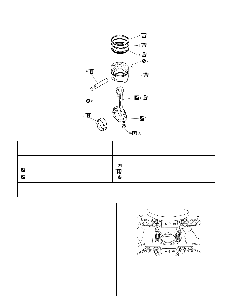
Pistons, Piston Rings, Connecting Rods and Cylinders Components

S6JB0A1416028

Pistons, Piston Rings, Connecting Rods and 
Cylinders Removal and Installation

S6JB0A1416029

Removal

1) Remove engine assembly from vehicle referring to 

“Engine Assembly Removal and Installation: For 
M16A Engine with VVT”.

2) Remove cylinder head referring to “Valves and 

Cylinder Head Removal and Installation: For M16A 
Engine with VVT”.

3) Mark cylinder number on all pistons, connecting rods 

and connecting rod caps using silver pencil or quick 
drying paint.

4) Remove rod bearing caps.
5) Install guide hose (1) over threads of rod bolts.

This prevents damage to bearing journal and rod bolt 
threads when removing connecting rod.

6) Decarbonize top of cylinder bore before removing 

piston from cylinder.

7) Push piston and connecting rod assembly out 

through the top of cylinder bore.

[A]: 1) Tighten all nuts to 15 N

⋅m (1.5 kgf-m).

2) Then retighten all nuts by turning through 45

°.

3) Repeat Step 2) again.

 7. Connecting rod bearing

1. Top ring

8. Piston pin

2. 2nd ring

9. Piston pin circlip

3. Oil ring

10. Bearing cap nut

4. Piston

: Tightening torque

5. Connecting rod

: See “A”

: Apply engine oil to sliding surface of each part.

6. Connecting rod bearing cap

: See “B”

: Do not reuse.

“A”: Apply engine oil to sliding surface except inner surface of big end, and rod bolts.

Check rod bolt, plastic deformation tightening bolt, for deformation referring to “Connecting rod bolt deformation (Plastic deformation tightening bolt) under 
“Piston Pins and Connecting Rods Inspection: For M16A Engine with VVT”, if it is reused

“B”: Point arrow mark on cap to crankshaft pulley side.

I2RH0B140108-01

I2RH0B140109-01

Engine Mechanical: For M16A Engine with VVT 1D-43

Installation

1) Apply engine oil to pistons, rings, cylinder walls, 

connecting rod bearings and crank pins.

NOTE
Do not apply oil between connecting rod and 
bearing or between bearing cap and bearing.


2) Install guide hoses (1) over connecting rod bolts.

These guide hoses protect crank pin and threads of 
rod bolt from damage during installation of 
connecting rod and piston assembly.

3) When installing piston and connecting rod assembly 

into cylinder bore, point front mark (1) on piston head 
to crankshaft pulley side.

4) Install piston and connecting rod assembly into 

cylinder bore. Use special tool (Piston ring 
compressor) to compress rings. Guide connecting 
rod into place on crankshaft.
Using a hammer handle, tap piston head to install 
piston into bore. Hold ring compressor firmly against 
cylinder block until all piston rings have entered 
cylinder bore.

Special tool
(A):  09916–77310

5) Install bearing cap (1):

Point arrow mark (2) on cap to crankshaft pulley 
side.
After applying engine oil to rod bolts and tighten cap 
nuts (3) gradually as follows.

NOTE
If connecting rod bolt is reused, make sure to 
check connecting rod bolt for deformation 
referring to “Connecting rod bolt deformation 
(Plastic deformation tightening bolt)” under 
“Piston Pins and Connecting Rods 
Inspection: For M16A Engine with VVT”.


a) Tighten all cap nuts to 15 N

⋅m (1.5 kgf-m, 11.0 lb-

ft).

b) Retighten them to 45

°

c) Repeat Step b) once again.

Tightening torque
Connecting rod bearing cap nut (a):  15 N

(1.5 kgf-m, 11.0 lb-ft) and then retighten by 
turning through 45

° twice

6) Install cylinder head referring to “Valves and Cylinder 

Head Removal and Installation: For M16A Engine 
with VVT”.

A: Crankshaft pulley side

B: Flywheel side

I2RH01140147-01

I2RH0B140110-01

I2RH0B140111-01

I2RH0B140112-01

1D-44 Engine Mechanical: For M16A Engine with VVT

Pistons, Piston Rings, Connecting Rods and 
Cylinders Disassembly and Assembly

S6JB0A1416030

Disassembly

1) Using piston ring expander, remove two 

compression rings (Top and 2nd) and oil ring from 
piston.

2) Remove piston pin from connecting rod as follows.

a) Ease out piston pin circlips (1), as shown.

b) Force piston pin out.

Assembly

1) Decarbonize piston head and ring grooves using a 

suitable tool.

2) Install piston pin to piston (1) and connecting rod (2):

a) After applying engine oil to piston pin and piston 

pin holes in piston and connecting rod.

b) Fit connecting rod as shown in the figure.
c) Insert piston pin to piston and connecting rod.
d) Install piston pin circlips (3).

NOTE
Circlip should be installed with its cut part 
facing as shown in the figure. Install so that 
circlip end gap comes within such range as 
indicated by arrow.


3) Install piston rings to piston:

• As indicated in the figure, 1st and 2nd rings have 

“T” mark (4) respectively. When installing these 
piston rings to piston, direct marked side of each 
ring toward top of piston.

• 1st ring (1) differs from 2nd ring (2) in thickness, 

shape and color of surface contacting cylinder 
wall.
Distinguish 1st ring from 2nd ring by referring to 
the figure.

• When installing oil ring (3), install spacer first and 

then two rails.

4) After installing three rings (1st, 2nd and oil rings), 

distribute their end gaps as shown in the figure.

I2RH0B140113-01

I2RH0B140114-01

1. Arrow mark

4. Oil ring upper rail gap

2. 1st ring end gap

5. Oil ring lower rail gap

3. 2nd ring end gap and oil ring spacer gap

I2RH0B140115-01

I5JB0A141025-01

IYSQ01142102-01

Engine Mechanical: For M16A Engine with VVT 1D-45

Cylinders, Pistons and Piston Rings Inspection

S6JB0A1416031

Cylinder
Visual inspection
Inspect cylinder walls for scratches, roughness or ridges 
which indicate excessive wear. If cylinder bore is very 
rough or deeply scratched, or ridged, rebore cylinder and 
use over size piston.

Cylinder bore diameter, taper and out-of-round
Using a cylinder gauge (1), measure cylinder bore in 
thrust and axial directions at two positions (“a” and “b”) 
as shown in the figure.
If any of the following conditions is noted, rebore 
cylinder.

1) Cylinder bore dia. exceeds limit.
2) Difference of measurements at two positions 

exceeds taper limit.

3) Difference between thrust and axial measurements 

exceeds out-of-round limit.

Cylinder bore diameter
Standard: 78.00 – 78.014 mm (3.0709 – 3.0714 in.)
Limit: 78.114 mm (3.075 in.)

Cylinder taper and out-of-round
Limit: 0.10 mm (0.004 in.)

NOTE
If any one of four cylinders has to be rebored, 
rebore all four to the same next oversize. 
This is necessary for the sake of uniformity 
and balance.


Piston
Visual inspection
Inspect piston for faults, cracks or other damages.
Damaged or faulty piston should be replaced.

Piston diameter
As indicated in the figure, piston diameter should be 
measured at a position 19.5 mm (0.77 in.) (“a”) from 
piston skirt end in the direction perpendicular to piston 
pin.

Piston diameter specification
Standard size: 77.953 – 77.968 mm (3.0690 – 3.0696 
in.)
Standard size (new one (with coating)): 77.969 – 
77.984 mm (3.0696 – 3.0702 in.)
Oversize (0.50 mm (0.0196 in.)): 78.453 – 78.468 mm 
(3.0887 – 3.0893 in.)

Piston clearance
Measure cylinder bore diameter and piston diameter to 
find their difference which is piston clearance. Piston 
clearance should be within specification as follows. If it is 
out of specification, rebore cylinder and use oversize 
piston.

NOTE
Cylinder bore diameters used here are 
measured in thrust direction at two positions.


“a”: 50 mm (1.96 in.)

“b”: 95 mm (3.74 in.)

I2RH0B140117-01

I2RH01140157-01


Content   ..  127  128  129  130   ..