Suzuki Grand Vitara JB416 / JB420 / JB419. Service manual - part 128
 

  Index      Suzuki     Suzuki Grand Vitara JB416 / JB420 / JB419 - service and repair manual 2007 year


Search            copyright infringement  


Content   ..  126  127  128  129   ..


Suzuki Grand Vitara JB416 / JB420 / JB419. Service manual - part 128


1D-38 Engine Mechanical: For M16A Engine with VVT

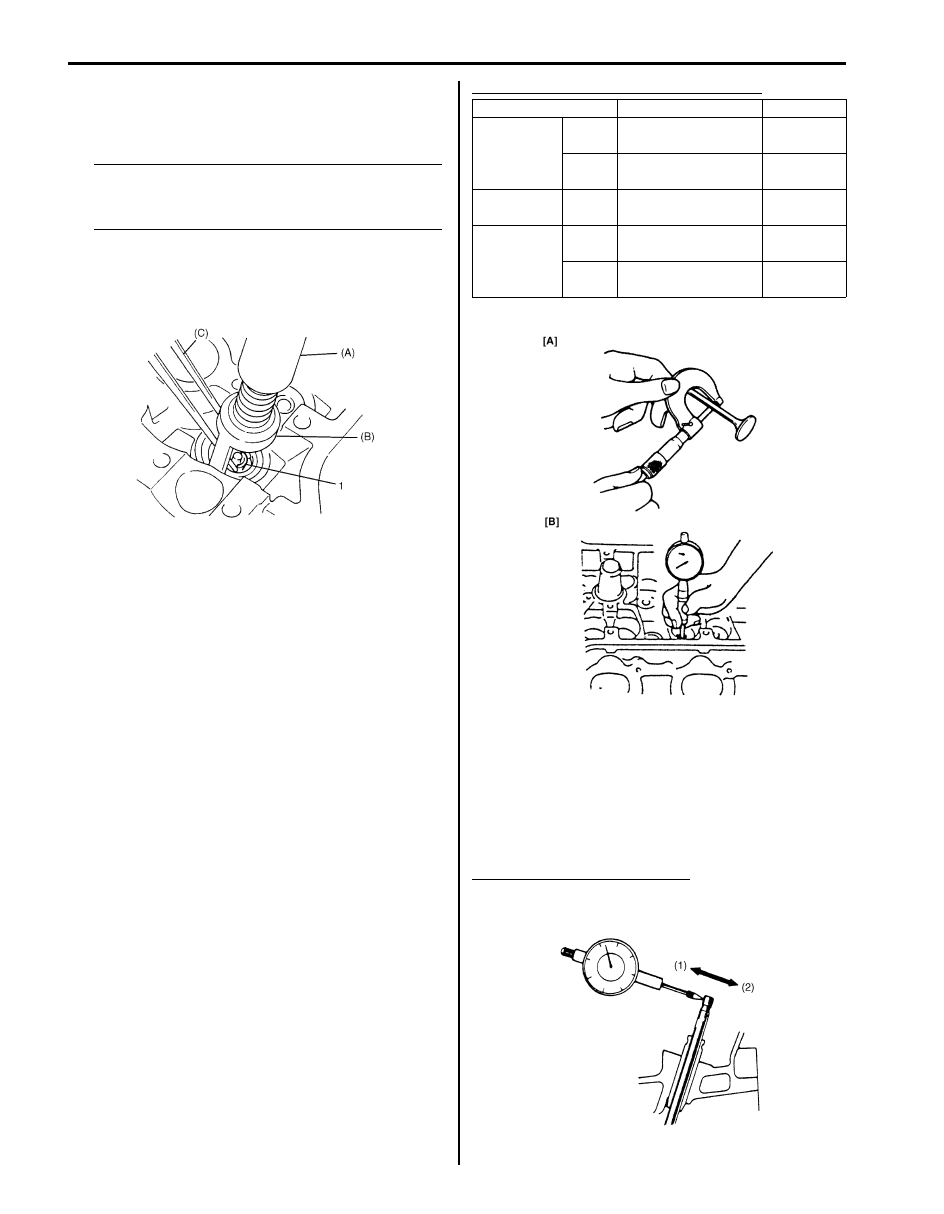
8) Using special tools (Valve lifter), compress valve 

spring and fit two valve cotters (1) into groove in 
valve stem.

NOTE
When compressing the valve spring, be 
carefully to free from damage in inside face 
of tappet installing hole.


Special tool
(A):  09916–14510
(B):  09916–14521
(C):  09916–84511

9) Install intake manifold referring to “Intake Manifold 

Removal and Installation: For M16A Engine with 
VVT”.

10) Install fuel injectors referring to “Fuel Injector 

Removal and Installation: For Petrol Engine Model in 
Section 1G”.

11) Install exhaust manifold referring to “Exhaust 

Manifold Removal and Installation (For M16 Engine 
Model): For Petrol Engine Model in Section 1K”.

Valves and Valve Guides Inspection

S6JB0A1416025

Valve Guide
Valve stem-to-guide clearance
Using a micrometer and bore gauge, take diameter 
readings on valve stems and guides to check stem-to-
guide clearance.
Be sure to take reading at more than one place along the 
length of each stem and guide.
If clearance exceeds limit, replace valve and valve 
guide.

Valve stem and valve guide specification

Valve stem end deflection
If bore gauge is not available, check end deflection of 
valve stem with a dial gauge instead.
Move stem end in directions (1) and (2) to measure end 
deflection.
If deflection exceeds its limit, replace valve stem and 
valve guide.

Valve stem end deflection limit
In: 0.14 mm (0.005 in.)
Ex: 0.18 mm (0.007 in.)

I2RH0B140101-01

Item

Standard

Limit

Valve stem 

diameter 

[A]

In

5.465 – 5.480 mm 

(0.2150 – 0.2157 in.)

Ex

5.440 – 5.455 mm 

(0.2142 – 0.2148 in.)

Valve guide 

bore [B]

In & Ex

5.500 – 5.512 mm 

(0.2165 – 0.2170 in.)

Stem-to-

guide 

clearance

In

0.020 – 0.047 mm 

(0.0008 – 0.0018 in.)

0.070 mm 

(0.0028 in.)

Ex

0.045 – 0.072 mm 

(0.0017 – 0.0028 in.)

0.090 mm 

(0.0035 in.)

I3RM0A140035-01

IYSQ01141096-01

Engine Mechanical: For M16A Engine with VVT 1D-39

Valve
Visual inspection
• Remove all carbon from valves.
• Inspect each valve for wear, burn or distortion at its 

face and stem end, as necessary, replace it.

• Inspect valve stem end face for pitting and wear. If 

pitting or wear is found there, valve stem end may be 
resurfaced, but not too much to grind off its chamber. 
When it is worn out too much that its chamber is gone, 
replace valve.

Valve head thickness
Measure thickness “a” of valve head. If measured 
thickness exceeds limit, replace valve.

Valve head thickness “a” (In and Ex)
Standard: 1.25 – 1.55 mm (0.049 – 0.061 in.)
Limit: 0.9 mm (0.035 in.)

Valve head radial runout
Check each valve for radial runout with a dial gauge and 
“V” block. To check runout, rotate valve slowly. If runout 
exceeds its limit, replace valve.

Valve head radial runout
Limit: 0.08 mm (0.003 in.)

Seating contact width
Create contact pattern on each valve in the usual 
manner, i.e., by giving uniform coat of marking 
compound to valve seat and by rotatingly tapping seat 
with valve head. Valve lapper (tool used in valve lapping) 
must be used. 
Pattern produced on seating face of valve must be a 
continuous ring without any break, and the width of 
pattern must be within specified range.

Standard seating width “a” revealed by contact 
pattern on valve face
Intake and Exhaust: 1.0 – 1.4 mm (0.0389 – 0.0551 
in.)

I2RH01140135-01

I2RH0B140102-01

I2RH01140136-01

I2RH0B140103-01

1D-40 Engine Mechanical: For M16A Engine with VVT

Valve seat repair
A valve seat not producing a uniform contact with its 
valve or showing width of seating contact that is out of 
specified range must be repaired by regrinding or by 
cutting and regrinding and finished by lapping.

1) Exhaust valve seat:

Use valve seat cutters (1) to make two cuts as 
illustrated in the figure. Two cutters must be used: 
the first for making 22

° angle, and the second for 

making 45

° angle. The second cut must be made to 

produce desired seat width.

Seat width for exhaust valve seat
“a”: 1.0 – 1.4 mm (0.0389 – 0.0551 in.)

2) Intake valve seat: 

Use valve seat cutters (1) to make three cuts as 
illustrated in the figure. Three cutters must be used: 
the 1st for making 22

° angle, the 2nd for making 60° 

angle, and 3rd for making 45

° angle. The 3rd cut 

(45

°) must be made to produce desired seat width.

Seat width for intake valve seat
“b”: 1.0 – 1.4 mm (0.0389 – 0.0551 in.)

3) Valve lapping:

Lap valve on seat in two steps, first with coarse size 
lapping compound applied to face and the second 
with fine-size compound, each time using valve 
lapper according to usual lapping method.

Cylinder Head Inspection

S6JB0A1416026

• Remove all carbon deposits from combustion 

chambers.

NOTE
Do not use any sharp-edged tool to scrape 
off carbon deposits. Be careful not to scuff or 
nick metal surfaces when decarbonizing. The 
same applies to valves and valve seats, too.


• Check cylinder head for cracks on intake and exhaust 

ports, combustion chambers, and head surface. Using 
a straightedge and thickness gauge, check flatness of 
gasketed surface at a total of 6 locations. If distortion 
limit is exceeded, correct gasketed surface with a 
surface plate and abrasive paper of about #400 
(Waterproof silicon carbide abrasive paper): place 
abrasive paper on and over surface plate, and rub 
gasketed surface against paper to grind off high spots. 
Should this fail to reduce thickness gauge readings to 
within limit, replace cylinder head. 
Leakage of combustion gases from this gasketed joint 
is often due to warped gasketed surface: such 
leakage results in reduced power output.

Distortion for cylinder head surface on piston side
Limit: 0.03 mm (0.001 in.)

I3RM0A140036-01

I2RH0B140105-01

I2RH0B140106-01

Engine Mechanical: For M16A Engine with VVT 1D-41

• Distortion of manifold seating faces: 

Check seating faces of cylinder head for manifolds, 
using a straightedge and thickness gauge, in order to 
determine whether these faces should be corrected or 
cylinder head replaced.

Distortion for cylinder head surface on intake and 
exhaust manifold
Limit: 0.05 mm (0.002 in.)

Cylinder Head Bolt
Measure each thread diameter of cylinder head bolt (1) 
at “A” on 83.5 mm (2.81 in.) from seat side of flange bolt 
and “B” on 115 mm (4.53 in.) from seat side of flange bolt 
by using a micrometer (2).
Then calculate difference in diameters (“A” – “B”). If it 
exceeds limit, replace with new one.

Cylinder head bolt diameter measurement points
“a”: 83.5 mm (2.81 in.)
“b”: 115 mm (4.53 in.)

Cylinder head bolt diameter difference (deformation)
Limit (“A” – “B”): 0.1 mm (0.004 in.)

Valve Spring Inspection

S6JB0A1416027

Valve Spring Free Length and Preload
Referring to data, check to be sure that each spring is in 
sound condition, free of any evidence of breakage or 
weakening. Remember, weakened valve springs can 
cause chatter, not to mention possibility of reducing 
power output due to gas leakage caused by decreased 
seating pressure.

Valve spring free length
Standard: 36.83 mm (1.450 in.)
Limit: 35.83 mm (1.411 in.)

Valve spring preload
Standard: 107 – 125 N (10.7 – 12.5 kg) for 31.50 mm 
(23.6 – 27.6 lb/1.240 in.)
Limit: 102 N (10.2 kg) for 31.50 mm (22.5 lb/1.240 in.)

Spring Squareness
Use a square and surface plate to check each spring for 
squareness in terms of clearance between end of valve 
spring and square. Valve springs found to exhibit a 
larger clearance than limit must be replaced.

Valve spring squareness
Limit: 1.6 mm (0.063 in.)

I2RH0B140107-01


“A”

“a”

“b”

“B”


1

1

2

I2RH0B140092-01

I2RH01140143-01

I2RH01140144-01


Content   ..  126  127  128  129   ..