Suzuki Grand Vitara JB416 / JB420 / JB419. Service manual - part 82
 

  Index      Suzuki     Suzuki Grand Vitara JB416 / JB420 / JB419 - service and repair manual 2007 year


Search            copyright infringement  


Content   ..  80  81  82  83   ..


Suzuki Grand Vitara JB416 / JB420 / JB419. Service manual - part 82


1A-275 Engine General Information and Diagnosis: For Diesel Engine Model

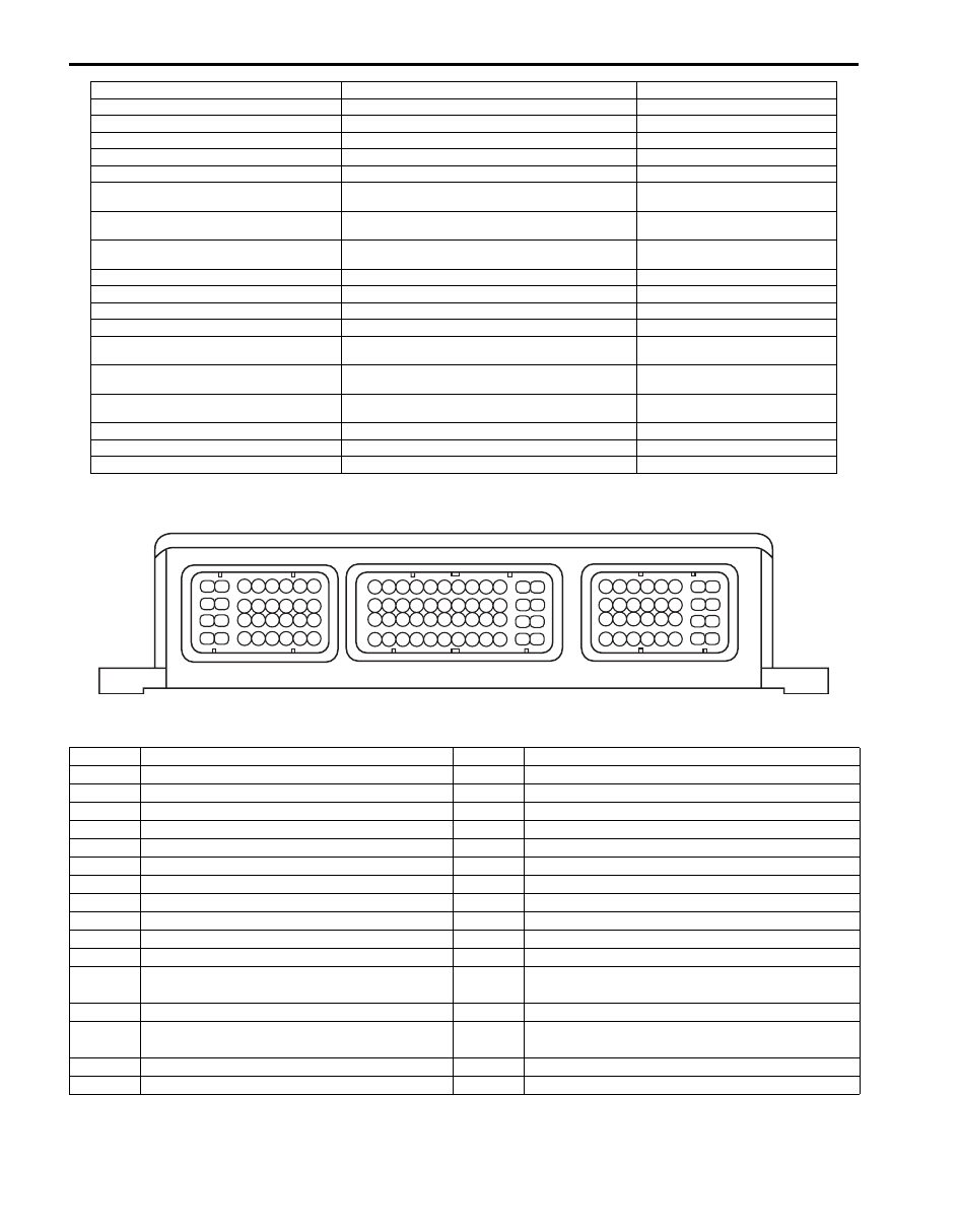
Terminal Arrangement of ECM Coupler (Viewed from Harness Side)

Connector: C85

5. Fuel injector No.4

26. Glow plug

49. ABS or ESP

® control module

6. CKP sensor

27. Fuel pump relay

50. 4WD control module

7. CMP sensor

28. Fuel pump

51. BCM

8. Exhaust gas temperature sensor 2*

29. Additional heater relay No.1

52. Immobilizer control module

9. Exhaust gas temperature sensor 3*

30. Additional heater relay No.2

53. Combination meter

10. Differential pressure sensor*

31. Additional heater relay No.3

54. Malfunction indicator light (MIL)

11. Boost pressure sensor

32. Additional heater plug

55. Injection warning light (gravity 1 

warning light)

12. Exhaust gas temperature sensor 1

33. A/C compressor relay

56. Red stop warning light (gravity 2 

warning light)

13. ECT sensor

34. A/C compressor

57. Diesel particulate filter warning 

light*

14. Fuel pressure sensor

35. Radiator fan relay No.1 (LOW)

58. Glow plug indicator light

15. EGR valve

36. Radiator fan relay No.2 (HIGH)

59. Fuel filter warning light

15-1. EGR motor

37. Radiator fan relay No.3 (HIGH)

60. Meter driver

15-2. EGR stroke sensor

38. Radiator fan motor No.1

61. Body ground

16. A/C refrigerant pressure sensor (if equipped 

with A/C)

39. Radiator fan motor No.2

62. Engine ground

17. Accelerator pedal position (APP) sensor 

assembly

40. Inlet throttle valve

63. Barometric pressure sensor

18. Cruise control switch

41. Boost pressure control solenoid valve

64. Steering angle sensor (ESP

® 

model)

19. Data link connector (DLC)

42. Turbocharger electric water pump relay

65. Keyless start control module

20. Fuel filter water detection sensor

43. Turbocharger electric water pump

21. Brake light switch

44. MAF sensor assembly with IAT sensor

33

34

39

40

41

42

43

44

35

36

37

38

45

46

47

48

9

10

11

12

13

14

1

3

5

7

2

4

6

8

15

16

17

18

19

20

21

22

23

24

25

26

27

28

29

30

31

32

1

3

7

15

16

17

18

19

20

21

22

23

24

25

26

27

28

29

30

31

32

2

4

6

8

9

10

11

12

13

14

5

1

2

3

4

5

6

7

8

9

10

11

12

13

14

15

16

17

18

19

20

21

22

23

24

25

26

27

28

29

30

31

32

C85

C86

E66

I5JB0B110008-01

Terminal

Circuit

Terminal

Circuit

1

Glow plug control module diagnosis input

17

Glow plug control module output

2

18

Radiator fan relay No.2 and 3 output

3

19

Additional heater relay No.2 and 3 output

4

20

Radiator fan relay No.1 output

5

Exhaust gas temperature sensor 1 signal

21

Fuel pump relay output 

6

22

Ground for exhaust gas temperature sensor 1

7

23

Boost pressure control solenoid valve

8

Brake lamp switch signal

24

9

Ground for A/C pressure sensor 

25

Fuel injector No.2 (low side)

10

26

Fuel injector No.3 (low side)

11*

Ground for exhaust gas temperature sensor 3

27

Fuel injector No.1 (low side)

12*

Ground for diesel particulate filter differential 
pressure

28

Fuel injector No.4 (low side)

13

Water detection signal in fuel filter

29

Fuel injector No.2 (high side)

14*

Diesel particulate filter differential pressure 
sensor signal

30

Fuel injector No.3 (high side)

15

Ground for EGR position sensor 

31

Fuel injector No.4 (high side)

16

32

Fuel injector No.1 (high side)

Engine General Information and Diagnosis: For Diesel Engine Model 1A-276

Connector: C86

Connector: E66

Terminal

Circuit

Terminal

Circuit

1

25

EGR valve output

2

26

EGR valve output

3

Main power supply

27

Inlet throttle valve feedback

4

28

5

29*

Exhaust gas temperature sensor 3 signal

6

30

7

Fuel flow actuator 

31*

Exhaust gas temperature sensor 2 signal

8

32

Fuel pressure sensor signal

9

33

Power source for A/C pressure sensor

10

34

11

Ground for ECT sensor

35

12

MAF sensor signal 

36

13

A/C pressure sensor signal

37

14

Main relay output

38

15

CMP sensor signal

39

Additional heater relay No.1

16

CKP sensor (low side)

40

Inlet throttle valve drive

17

CKP sensor (high side)

41

Turbocharger electric water pump relay

18

Ground for CMP sensor and exhaust gas 
temperature sensor 2

42

Power source for boost pressure sensor and 
differential pressure sensor 

19

Boost pressure sensor signal 

43

Power source for EGR position sensor 

20

EGR position sensor signal

44

21

45

Ground for boost pressure sensor

22

IAT sensor signal

46

Ground for fuel pressure sensor 

23

ECT sensor signal

47

Power source for MAF sensor

24

Ground for MAF sensor

48

Power source for fuel pressure sensor

Terminal

Circuit

Terminal

Circuit

1

Ground for ECM

17

Cruise control switch signal

2

Main power supply

18

3

APP sensor 1 signal 

19

4

Power source for APP sensor 1

20

Cruise control main switch signal

5

Ground for APP sensor 1

21

APP sensor 2 signal 

6

22

7

Ground for ECM

23

Ground for cruise control switch

8

Ground for ECM

24

9

25

10

26

CAN (low) communication line (active low 
signal)

11

Ignition switch signal

27

Ground for APP sensor 2

12

28

Brake light switch signal

13

A/C compressor relay output

29

14

30

CPP switch signal

15

Power source for APP sensor 2

31

12 V serial communication line of data link 
connector

16

32

CAN (high) communication line (active high 
signal)

1A-277 Engine General Information and Diagnosis: For Diesel Engine Model

Component Location

Electronic Control System Components Location

S6JB0A1123001

NOTE

• The figure shows left-hand steering vehicle. For right-hand steering vehicle, alphabets / numbers / 

parts with asterisks (**) are installed at the opposite side.

• For vehicle without diesel particulate filter, alphabets / numbers/parts with asterisk (*) below are not 

equipped.


1

2

3

e

c

B

A

f

g

h

i

C

4

D

E**

j

k

l

m

F**

q

o

r

G**

s*

p

n

I**

H**

6**

5**

K

14

J

u

9 8

t

7

10*

11*

L**

M**

12

v

13*

w

x

y

a

15

a

b

d

I6JB0A112005-02

Information sensors

Control devices

Others

1. MAF sensor assembly with IAT sensor 

a: Fuel injector

A: ECM

2. CMP sensor 

b: Glow plug

B: ABS or ESP

® control module

3. A/C refrigerant pressure sensor

c: Fuel flow actuator

C: Fuel filter including fuel heater 

4. Fuel filter water detection sensor 

d: Additional heater plug

D: Glow plug control module

5. Brake light switch**

e: Turbocharger electric water pump

E: Fuse box No.2**

6. Accelerator pedal position (APP) sensor**

f: Radiator fan relay No.3 (HIGH)

F: BCM**

7. CKP sensor

g: Radiator fan relay No.2 (HIGH)

G: Combination meter**

8. Boost pressure sensor

h: Radiator fan relay No.1 (LOW)

H: Immobilizer control module**

9. ECT sensor

i: Fuel pump relay

I: Data link connector**

10. Exhaust gas temperature sensor 3*

j: Turbocharger electric water pump relay

J: A/C evaporator outlet temp. 

sensor

11. Exhaust gas temperature sensor 2*

k: Main relay

K: Fuel pump

12. Exhaust gas temperature sensor 1

l: A/C compressor relay

L: Battery**

13. Differential pressure sensor*

m: Fuel heater relay

M: 4WD control module**

14. Rear wheel speed sensor (VSS)

n: MIL

15. Fuel pressure sensor

o: Fuel filter warning light
p: Injection warning light (gravity 1 warning light)
q: Glow plug indicator light

Engine General Information and Diagnosis: For Diesel Engine Model 1A-278

Diagnostic Information and Procedures

Malfunction Indicator Lamp (MIL) Check

S6JB0A1124001

Malfunction indicator lamp (1) signals an antipollution 
system failure. 
Check that it lights up for 3 seconds after the ignition 
switch is turned ON, and then it goes OFF (automatic 
test procedure). 
If light remains ON after an automatic test procedure, go 
to “DTC Check: For Diesel Engine Model”.
After the ignition switch is turned ON, if light does not 
light up or remains ON, check that malfunction indicator 
lamp circuit.

Injection Warning Light (Gravity 1 Fault) Check 

S6JB0A1124002

Injection warning light (1) serves to indicate proper 
functioning and to signal system failures.
After the ignition switch is turned ON, if lights remains 
ON, go to “DTC Check: For Diesel Engine Model”.
If injection warning light flashes ON and OFF, there is 
some trouble in the immobilizer control system referring 
to “On-Board Diagnostic System Description (Self-
diagnosis Function): For Diesel Engine Model in Section 
10C”.

Red Stop Warning Light (Gravity 2 Fault) Check

S6JB0A1124003

Red stop warning light (1) serves to indicate proper 
functioning and to signal system failures. 
After the ignition switch is turned ON. if light remains ON, 
go to “DTC Check: For Diesel Engine Model”.

r: Red stop warning light (gravity 2 warning light)

s: Diesel particulate filter warning light*

t: Inlet throttle valve

u: EGR valve 

v: Boost pressure control solenoid valve

w: Additional heater relay No.1

x: Additional heater relay No.2
y: Additional heater relay No.3

Information sensors

Control devices

Others

1

I5JB0B110011-02

1

I5JB0B110012-02

1

I5JB0B110013-02


Content   ..  80  81  82  83   ..