Suzuki Grand Vitara JB416 / JB420 / JB419. Service manual - part 80
1A-267 Engine General Information and Diagnosis: For Diesel Engine Model
General Description
Statement on Cleanliness and Care
S6JB0A1121007
An automobile engine is a combination of many
machined, honed, polished and lapped surfaces with
tolerances that are measured in the thousands of an
millimeter (ten thousands of inch).
Accordingly, when any internal engine parts are
serviced, care and cleanliness are important.
It should be understood that proper cleaning and
protection of machined surfaces and friction areas is part
of the repair procedure. This is considered standard
shop practice even if not specifically stated.
• A liberal coating of engine oil should be applied to
friction areas during assembly to protect and lubricate
the surfaces on initial operation.
• Whenever valve train components, pistons, piston
rings, connecting rods, rod bearings, and crankshaft
journal bearings are removed for service, they should
be retained in order.
At the time of installation, they should be installed in
the same locations and with the same mating
surfaces as when removed.
• Battery cables should be disconnected before any
major work is performed on the engine.
Failure to disconnect cables may result in damage to
wire harness or other electrical parts.
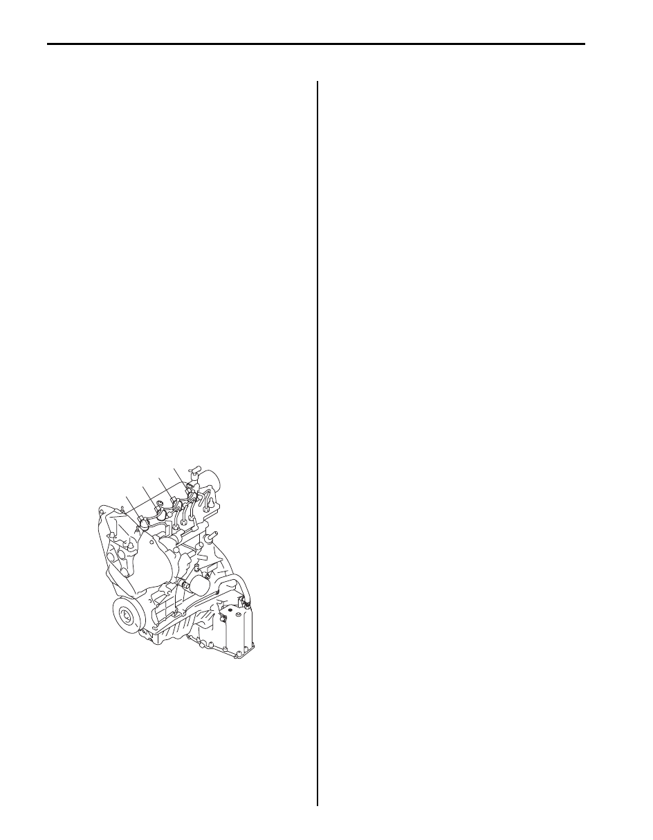
• The four cylinders of the engine are identified by
numbers; No.1 (1), No.2 (2), No.3 (3) and No.4 (4) as
counted from flywheel side to crankshaft pulley side.
Engine Diagnosis General Description
S6JB0A1121002
The engine and emission control system in this vehicle
are controlled by ECM. ECM has an On-Board
Diagnostic system which detects a malfunction in this
system and abnormality of those parts that influence the
engine exhaust emission. When diagnosing engine
troubles, be sure to have full understanding of the outline
of “On-Board Diagnostic System Description: For Diesel
Engine Model” and each item in “Precautions in
Diagnosing Trouble: For Diesel Engine Model” and
execute diagnosis according to “Engine and Emission
Control System Check: For Diesel Engine Model”.
There is a close relationship between the engine
mechanical, engine cooling system, exhaust system,
etc. and the engine and emission control system in their
structure and operation. In case of an engine trouble,
even when the warning light (MIL, injection warning light,
and/or red stop warning light) doesn’t turn ON, it should
be diagnosed according to this flow table.
On-Board Diagnostic System Description
S6JB0A1121003
ECM in this vehicle has the following functions.
• When the ignition switch is turned ON with the engine
at a stop, MIL (1), turns ON to check the warning light
and its circuit.
• When ECM detects a malfunction, it makes injection
warning light (gravity 1 fault) (2) and/or red stop
warning light (gravity 2 fault) (3) in the meter cluster of
the instrument panel turn ON and stores the
malfunction area in its memory.
• When ECM detects a malfunction which gives an
adverse effect to vehicle emission while the engine is
running, it makes the malfunction indicator lamp in the
meter cluster of the instrument panel turn ON and
stores the malfunction area in its memory.
1
2
3
4
I5JB0B110001-01