Suzuki Grand Vitara JB416 / JB420 / JB419. Service manual - part 78
1A-259 Engine General Information and Diagnosis: For Petrol Engine Model
Radiator Cooling Fan Low Speed Control System Check
S6JB0A1114087
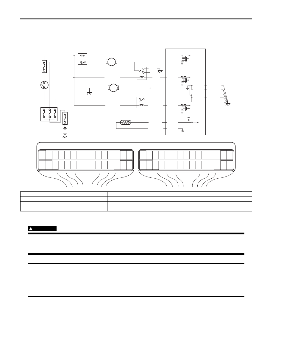
Wiring Diagram
Troubleshooting
WARNING
!
Keep hands, tools, and clothing away from engine cooling fan to help prevent personal injury. This fan
is electric and can come on whether or not the engine is running. The fan can start automatically in
response to the ECT sensor with the ignition switch at the “ON” position.
NOTE
• Before performed troubleshooting, be sure to read the “Precautions of ECM Circuit Inspection: For
• When measuring circuit voltage, resistance and/or pulse signal at ECM connector, connect the
special tool to ECM and/or the ECM connectors referring to “Inspection of ECM and Its Circuits: For
Petrol Engine Model”.
E23
C37
3
4
18
19
5
6
7
10
11
17
20
47
46
49
50
51
21
22
52
16
25
9
24
14
29
55
57
54 53
59
60
58
2
26
27
28
15
30
56
48
32
31
34
35
36
37
40
42
39 38
44
45
43
41
33
1
12
13
23
8
3
4
18
19
5
6
7
10
11
17
20
47
46
49
50
51
21
22
52
16
25
9
24
14
29
55
57
54 53
59
60
58
2
26
27
28
15
30
56
48
32
31
34
35
36
37
40
42
39 38
44
45
43
41
33
1
12
13
23
8
5V
RED/BLK
E23-46
E23-47
BLU/RED
BLU/YEL
BLU/BLK
E23-48
PPL/YEL
GRY/GRN
C37-24
C37-57
1
BLK
RED
YEL/GRN
C37-15
C37-29
C37-48
BLK/ORN
C37-58
C37-30 BLK/ORN
BLK/YEL
BLK/YEL
BLK/YEL
RED/YEL
BLK
BLU
BLU
YEL/GRN
BLU/WHT
YEL/GRN
8
4
5
9
2
10
3
6
7
I5JB0A110105-01
1. Fuse box No.1
5. Radiator cooling fan relay No. 3
9. ECT sensor
2. Ignition switch
6. Radiator cooling fan motor No.1
10. “IG2 SIG” fuse
3. Radiator cooling fan relay No. 1
7. Radiator cooling fan motor No.2
4. Radiator cooling fan relay No. 2
8. ECM