Suzuki Grand Vitara JB416 / JB420 / JB419. Service manual - part 81
 

  Index      Suzuki     Suzuki Grand Vitara JB416 / JB420 / JB419 - service and repair manual 2007 year


Search            copyright infringement  


Content   ..  79  80  81  82   ..


Suzuki Grand Vitara JB416 / JB420 / JB419. Service manual - part 81


1A-271 Engine General Information and Diagnosis: For Diesel Engine Model

Diesel Particulate Filter Regeneration 
Description

S6JB0A1121006

As Diesel Particulate Filter is a device to trap the diesel 
particulate (PM), it is necessary that the accumulated 
PM is burned and diesel particulate filter regenerated.
There are three ways to regenerate diesel particulate 
filter.
• “Natural regeneration” by catalysis and exhaust gas 

temperature

• “Forced regeneration” by post-injection
• “After-sales regeneration” by using SUZUKI scan tool
And, here is the mechanism to regenerate diesel 
particulate filter.
1. Diesel particulate filter, trapping PM, carries out 

“Natural regeneration” according to the driving 
condition. The driver will not find it.

2. ECM consistently monitors the exhaust gas 

temperature, injection quantity, driving time, vehicle 
speed, PM mass etc. In case of the long-time idling 
and traffic jam at low speed that cause lowering the 
exhaust gas temperature, PM is accumulated 
gradually.
When “Natural regeneration” becomes insufficient 
(PM mass exceeds 25 g), ECM will perform “Forced 
regeneration” by the post-injection at the point of 
appropriate driving condition. The post-injection will 
heat the exhaust gas temperature to enable “Forced 
regeneration”. In this situation, any warning indicator 
will not come on. Therefore, the driver will not 
recognize that “Forced regeneration” is performed.

3. If “Forced regeneration” is interrupted by the engine 

stop, long-time idling and traffic jam at low speed 
that do not keep the specified exhaust gas 
temperature, ECM will memorize it as “Regeneration 
failure”. When the “regeneration failure” number (5 
times) or PM mass reach at the specified conditions 
(PM mass exceeds 42 g), ECM will find it as 
“impossible to regenerate by diesel particulate filter 
itself and incapable of continuing the driving” and 
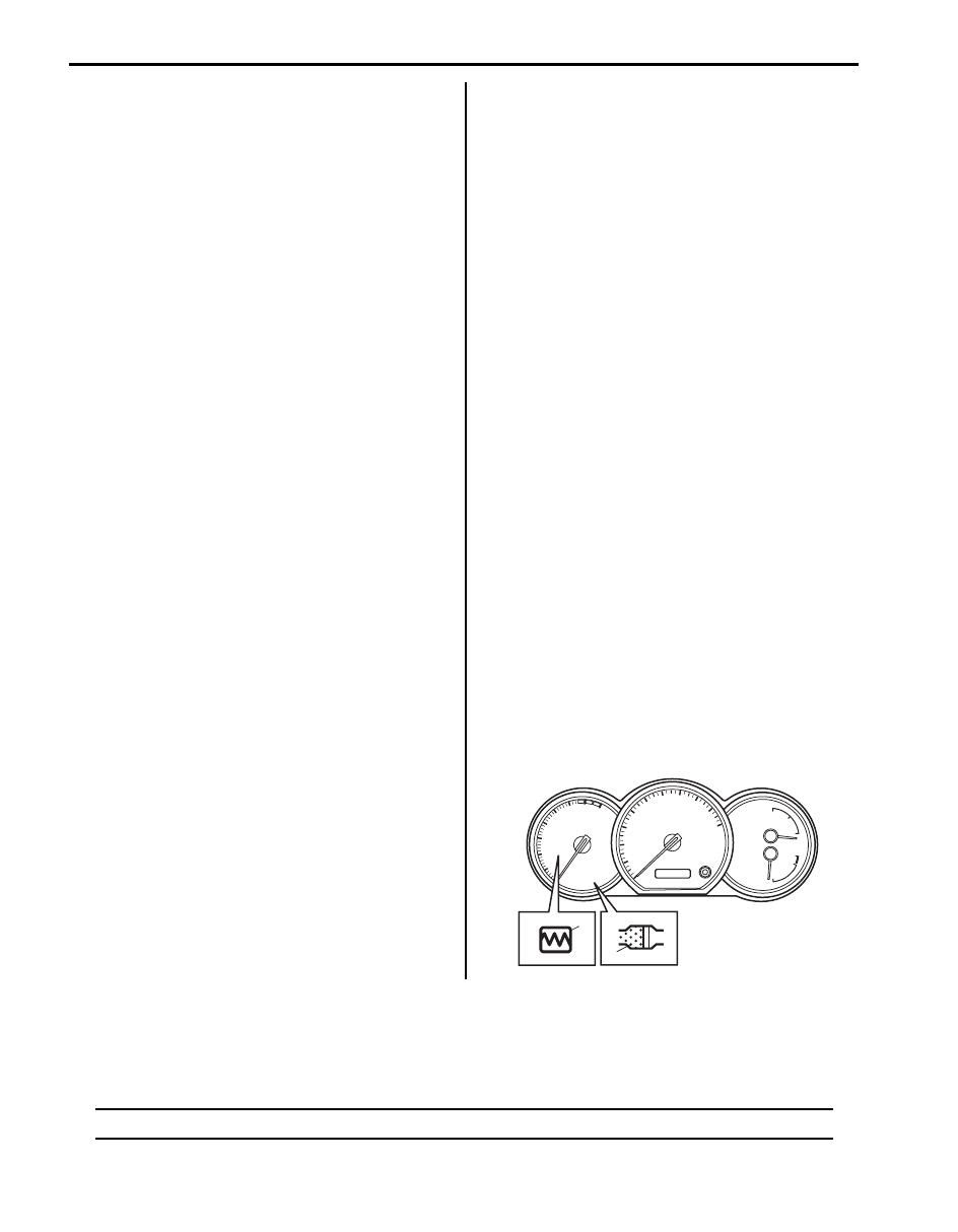
ask the driver for a help. This is “Speed request” 
announced to the driver by diesel particulate filter 
warning light (1) in combination meter. Then, the 
driver will be asked to increase the vehicle speed 
more than 75 km/h (47 MPH) on the average for 
heating the exhaust gas temperature. If the 
regeneration is completed by “natural regeneration” 

or “Forced regeneration” when accumulating 
“regeneration failure”, the accumulation of 
“regeneration failure” will be reset.

4. After the driver fulfills “speed request” for the 

regeneration and PM mass falls to the specified 
amount (5 ~ 8 g), the regeneration will complete and 
diesel particulate filter warning light be turned OFF. It 
will take about 20 minutes to complete the 
regeneration if the regeneration driving is performed 
properly. During the regeneration driving, “Forced 
regeneration” will go simultaneously to hasten the 
increase of exhaust gas temperature and shorten 
the time of regeneration. When the engine stops 
before diesel particulate filter warning light is turned 
OFF, PM mass that should be decreased will be 
calculated at starting the engine next time. At that 
time, if PM mass does not fall to the specified 
amount, diesel particulate filter warning light will 
come on again and the vehicle continue to ask the 
driver for regeneration driving.

5. If the regeneration driving is not achieved and diesel 

particulate filter becomes almost clogged while 
“Speed request” is on, injection warning light (Gravity 
1 Fault) (2) in combination meter will come on. Also, 
to prevent diesel particulate filter from melting and 
cracking, ECM will take following actions;

1) EGR (Exhaust Gas Recirculation) will be cut off to 

avoid generating the extra PM.

2) “Forced regeneration” function will stop.
3) Driving performance will be limited by lowering the 

engine torque to avoid “Natural regeneration”.

Therefore, the driver will recognize the malfunction of 
diesel particulate filter.
In this situation, “After-sales regeneration” using 
SUZUKI scan tool will be necessary or diesel particulate 
filter has to be replaced in the worst case.

Schematic and Routing Diagram

Electronic Control System Diagram

S6JB0A1122001

NOTE
For vehicle without diesel particulate filter, numbers / parts with asterisk (*) below are not equipped.


2

1

I5JB0B110016-01

Engine General Information and Diagnosis: For Diesel Engine Model 1A-272

23

2*

9

10

11

12

13

14

16

15

4*

3*

5

6

7

17

8

20

21

22

23

18

36

37

38

39

40

57

41

55

42 

43

44

45

46

47

48

49

50

33

51

54

52

53

19

24

25

26

27

28

29

30

31

32

33

34

35

1

56

I6JB0A112003-02

1. ECM

20. Boost pressure control solenoid valve

39. 4WD control module

2. Exhaust gas temperature sensor 3*

21. Common rail (High pressure fuel injection 

rail)

40. Immobilizer control module

3. Diesel particulate filter*

22. Fuel pressure sensor

41. BCM

4. Exhaust gas temperature sensor 2*

23. Fuel injector

42. Electric load

1A-273 Engine General Information and Diagnosis: For Diesel Engine Model

Electronic Control System Wiring Circuit Diagram

S6JB0A1122002

NOTE
For vehicle without diesel particulate filter, numbers / parts with asterisk (*) below are not equipped.


5. Oxidation catalytic converter

24. Vacuum pump

43. A/C refrigerant pressure sensor 

6. Turbocharger

25. CMP sensor

44. Cruise control switch

7. Boost pressure control valve actuator

26. Glow plug

45. Radiator fan motor relay

8. Exhaust gas temperature sensor 1

27. ECT sensor

46. Additional heater

9. Differential pressure sensor*

28. CKP sensor

47. Turbocharger electric water pump

10. Fuel flow actuator

29. EGR valve

48. A/C compressor magnet clutch

11. Injection pump

30. Boost pressure sensor

49. Data link connector

12. Fuel filter

31. Inlet throttle valve

50. Brake light

13. Fuel heater

32. Glow plug control module

51. Ignition switch

14. Fuel filter water detection sensor

33. Clutch pedal position (CPP) switch

52. Main relay

15. Priming pump

34. Brake light switch

53. Fuel heater relay

16. Fuel pump 

35. Accelerator pedal position (APP) sensor

54. Battery

17. MAF sensor assembly with IAT sensor

36. Wheel speed sensor (VSS signal)

55. Barometric pressure sensor

18. Air cleaner

37. ABS or ESP

® control module

56. EGR cooler

19. Intercooler

38. Combination meter

57. Keyless start control module

Engine General Information and Diagnosis: For Diesel Engine Model 1A-274

1

20

22

23

24

30

31

32

32

33

34

35

36

37

38

39

40

41

42

43

44

63

45

46

47

48

29

25

: 61
: 62

IG1

IG2

27

28

RED

WHT

2

3

4

5

6

7

8*

9*

10*

11

12

13

14

15

15-1

15-2

16

17

18

19

49

53

50

64

51

52

65

21

C85-32
C85-27
C85-29
C85-25
C85-30
C85-26
C85-31
C85-28

PNK

RED

PNK/BLK

RED/BLK

PNK/GRN

RED/GRN

PNK/BLU

RED/BLU

E66-28

E66-30

C85-8

E66-13

C86-39

C85-19

C86-27

C85-23

C86-41

C86-40

C86-7

C86-24
C86-22

C86-47
C86-12

C85-17

C85-1

E66-2

E66-11

C86-14

C86-3

E66-1
E66-7
E66-8

C85-18

C85-20

GRN/WHT

BLU

YEL/GRN

PNK

YEL/BLK

YEL/RED

PNK/GRN

BLU

WHT/BLU

PNK/BLK

PNK

GRY/BLK

BLU/RED

GRY/RED
BLU/WHT

BRN/YEL

GRY

BLU/BLK

BLK/WHT

BLU/YEL
BLU/BLK

BLK
BLK
BLK

RED/YEL

RED/BLK

C85-21

BRN/YEL

C85-13

E66-31

E66-32
E66-26

C85-12

C85-14

C86-25

C86-26

C85-11

C86-29

C86-31

C86-18

C86-15

C86-16

C86-17

C86-46

C86-32

C86-48

E66-23

E66-17

E66-20

C85-15

C86-20

C86-43

C86-45

C86-19

C86-42

E66-27

E66-21

E66-15

E66-5

E66-3

E66-4

C85-22

C85-5

C86-11

C86-23

C85-9

C86-13

C86-33

PNK/GRN

+B

+B

+B

PPL/WHT

WHT/RED
WHT/BLU

BLK/RED

RED/BLU

BLU

RED

BLK/YEL

BLU/ORN

RED/YEL

BLK/YEL

WHT/GRN

WHT/RED

WHT/BLU

BLK/BLU

BRN/YEL

BRN/RED

BLK/YEL

LT GRN

BLK/WHT

LT GRN/BLK

LT GRN

LT GRN/RED

GRY/GRN

RED/WHT

GRY/RED

BLU/YEL

BLU/GRN

ORN/BLU

ORN

WHT/BLU

WHT

BLU/YEL

RED/BLK

BLU/YEL

PNK/WHT

GRY/GRN

BRN/BLK

GRY/RED

BRN

BRN/WHT

BRN/BLK

BRNYEL

BLK

BLU

BLK

BLU/RED

BLU/WHT

BLU/BLK

+B

60

54 55 56 57* 58 59

12V

26

I6JB0A112004-03

1. ECM

22. Brake light

45. Main relay

2. Fuel injector No.1

23. CPP switch

46. Ignition switch

3. Fuel injector No.2

24. Fuel flow actuator

47. Fuel heater relay

4. Fuel injector No.3

25. Glow plug control module

48. Fuel heater


Content   ..  79  80  81  82   ..