Renault Master (2023 year). Manual in english - page 4
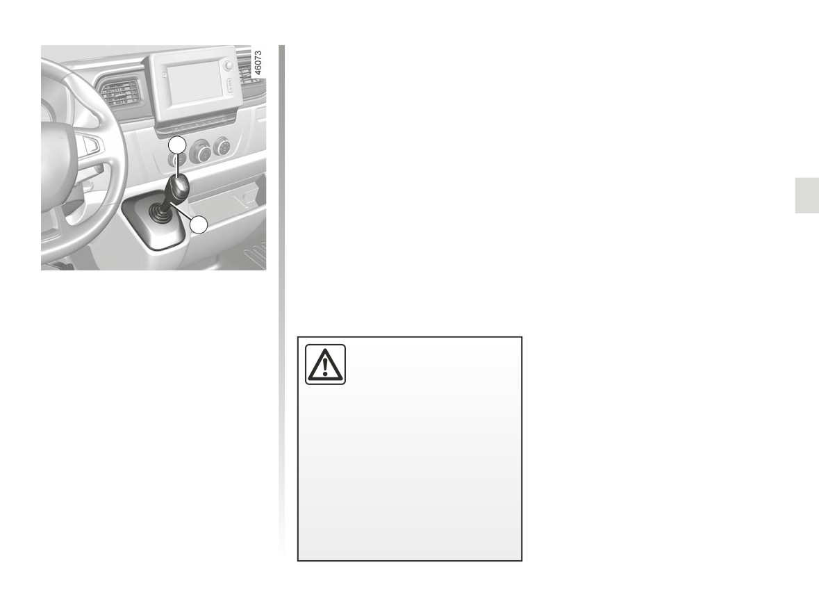
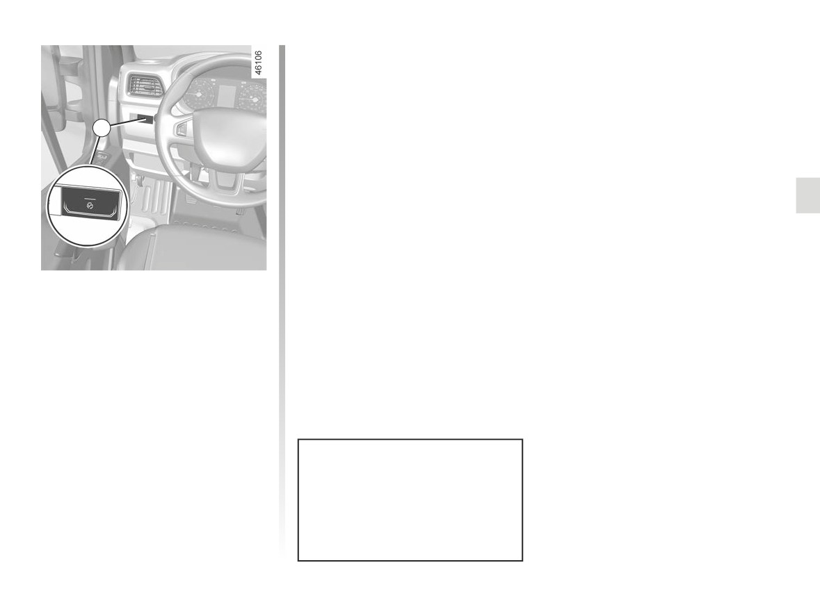
GEAR LEVER
1
2
Gear lever
Selecting reverse gear
With the vehicle stationary, move the
gear lever into neutral then into reverse.
Follow the grid drawn on gear knob 1,
An impact to the underside
lift ring 2 against the gear knob to select
of the vehicle (e.g.: striking
reverse gear.
a post, raised kerb or other
The reversing lights will come on as
street furniture) may result
soon as reverse gear is selected (with
in damage to the vehicle (e.g.: de-
the ignition on).
formation of an axle).
Vehicles with a sequential gearbox
To avoid any risk of accident, have
➥ 2.69 .
your vehicle checked by an ap-
proved Dealer.
2.19
CarManuals2.co
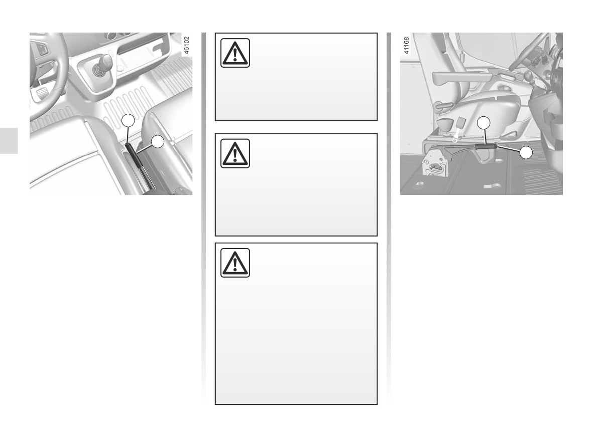
HANDBRAKE
Make sure that the hand-
brake is properly released
when driving (red indicator
light off), otherwise over-
heating, or even damage, may
occur.
2
4
1
When the vehicle is
stopped, depending on the
3
gradient and/or the vehicle
load, it may be necessary to
apply the handbrake by at least two
further notches and engage a gear
Handbrake
(1st or reverse).
Pull-up handbrake
(depending on the vehicle)
To apply:
Pull lever 1 upwards. Check that the
To apply:
vehicle is immobilised. The warning
Pull lever 4 upwards then release it. It
An impact to the underside
returns to the horizontal position.
light }
on the instrument panel will
of the vehicle (e.g.: striking
come on.
a post, raised kerb or other
To release
street furniture) may result
To release:
in damage to the vehicle (e.g.: de-
Press button 3 and pull lever 4 upwards
Pull lever 1 up slightly, press button 2
formation of an axle).
then place it in a horizontal position.
and then lower the lever to the floor.
To avoid any risk of accident, have
The warning light }
on the instru-
your vehicle checked by an ap-
ment panel will go out.
proved Dealer.
2.20
CarManuals2.co
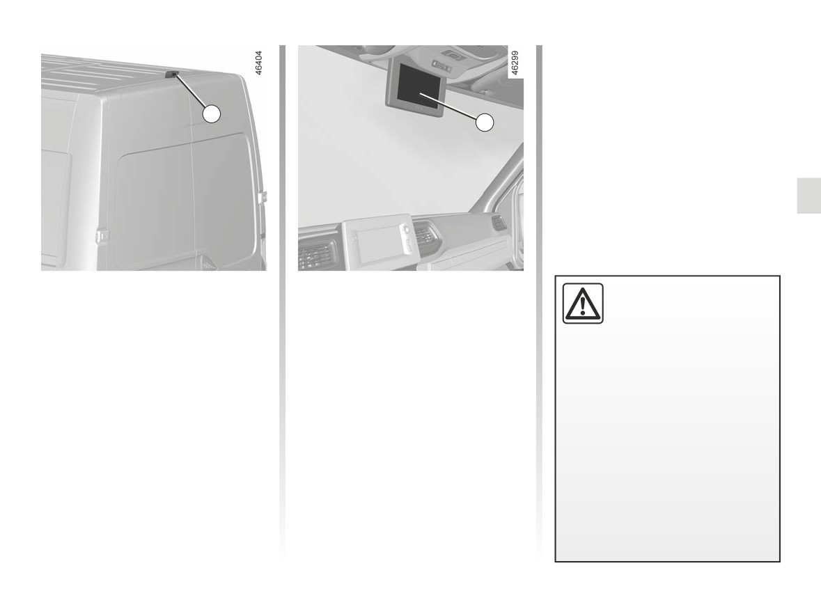
REAR CAMERA (1/3)
1
2
When the ignition is switched on, the 2
Special features
This function is an additional
screen on the roof centre console dis-
The camera is equipped with an auto-
aid. It cannot, therefore,
plays the view behind the vehicle that is
matic de-icer which is activated when
under any circumstances
transmitted by the camera 1.
the temperature is below approximately
replace the vigilance or the
Note: the 2 screen view may be may be
8°C.
responsibility of the driver.
displayed left to right.
Make sure that the 1 camera is not ob-
The driver should always be ready
scured (by dirt, mud, snow, condensa-
for sudden incidents while driv-
tion etc.).
ing: always ensure that there are
no small, narrow moving obstacles
(such as a child, animal, pushchair,
bicycle, stone, post, etc.) in the blind
spot when manoeuvring.
2.21
CarManuals2.co
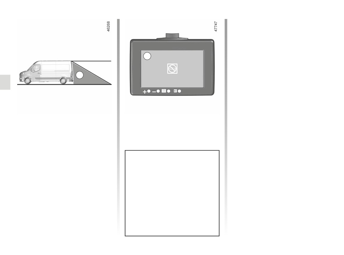
REAR CAMERA (2/3)
Switching off the function
The display switches of:
- up to approximately ten seconds
after the reverse gear is engaged;
- 30 seconds after the ignition is
2
switched off.
A
Operation
The camera’s field of vision does not
cover the entire area behind the vehi-
cle, particularly the blind spot area A.
On vehicles equipped with the Stop
and Start function, the display remains
active when the engine is in standby.
➥ 2.4.
Objects which appear on the edge
of screen 2 may be deformed.
In very bright light (snow, vehicle
in sunshine, etc.), the camera view
may be partially obscured.
In low brightness or poor weather,
the image on the screen may be dis-
torted.
2.22
CarManuals2.co
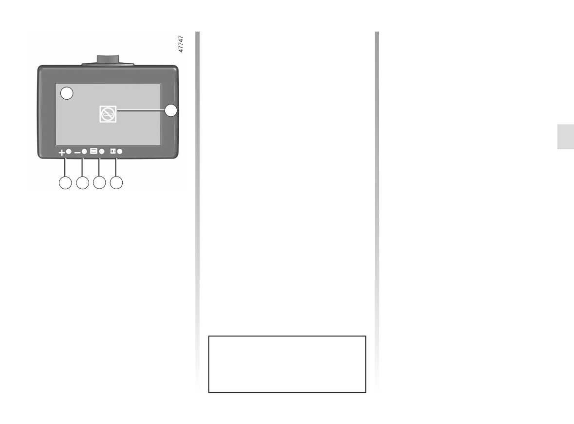
REAR CAMERA (3/3)
Adjustment of brightness modes
Operating faults
Once the mode has been selected,
When the system detects an operating
press button 5 as many times as re-
fault, warning light B appears temporar-
quired to access the type of setting you
ily on screen 2.
wish to change:
This may be caused a temporary fault
- brightness;
2
affecting the camera or screen (clear-
- contrast;
ness, fixed image, delayed communi-
B
- colour;
cation, etc.).
- RESET: resets factory settings.
If the warning light remains on, consult
Press buttons 3 (+) or 4 (-) to adjust the
an approved dealer.
setting.
Note: only the first three modes (“day”,
“intermediary” and “night”) can be set.
3
4
5
6
Adjustment of the display
Accessing the brightness modes
Press button 6 repeatedly to select one
of the four preset brightness modes:
- “day” mode;
- “intermediary” mode;
- “night” mode;
- “black screen” mode: allows suspen-
sion of the display. Screen 2 displays
a black image accompanied by the
“OFF” message. To exit this mode,
press button 6 again to access the
first brightness mode (“day” mode).
Each time the vehicle is started,
the function returns to the settings
saved at the last engine stop.
2.23
CarManuals2.co

DRIVING CORRECTION DEVICES AND AIDS (1/6)
Depending on the vehicle, this is com-
Anti-lock braking system
Operating faults:
posed of:
(ABS)
-
and x
are shown on
- anti-lock braking system (ABS);
Under heavy braking, the ABS prevents
the instrument panel with the mes-
- the electronic stability control
the wheels from locking, allowing the
sages “WARNING: Check ABS” and
(ESC) with understeer control,
stopping distance to be managed and
“WARNING: Check ESC”: this con-
side winds assistance and trac-
keeping control of the vehicle.
firms that the ABS, ESC and emer-
tion control;
Under these circumstances, the vehi-
gency braking systems are deacti-
cle can be steered to avoid an obstacle
- driver assistance with a trailer;
vated. Braking is always enabled;
whilst braking. In addition, this system
- emergency brake assist;
can increase stopping distances, par-
- x
, D
,
and
®
ticularly on roads with low surface grip
– traction control;
lit on the instrument panel accom-
(wet ground etc.).
panied by the message “WARNING:
- hill start assistance.
You will feel a pulsation through the
Braking System”: this indicates a
Other driving assistance systems are
brake pedal each time the system is
fault with the braking system.
detailed on the following pages.
activated. The ABS does not in any
way improve the vehicle's physical per-
In both cases, please consult an
formance relating to the road surface
Authorised Dealer.
and road-holding. It is still essential to
follow the rules of good driving practice
(such as driving at a safe distance from
the vehicle in front etc.).
Your braking systems
are partially operational.
However, it is dangerous
In an emergency, apply firm and
to brake suddenly and it
continuous pressure to the brake
is essential to stop immediately, as
pedal. There is no need to pump
soon as traffic conditions allow. Call
it repeatedly. The ABS will modu-
an approved Dealer.
late the force applied in the braking
system.
2.24
CarManuals2.co

DRIVING CORRECTION DEVICES AND AIDS (2/6)
Electronic stability program
Understeer control
(ESC) with understeer control
This system optimises the action of the
and traction control
ESC in the case of pronounced under-
steer (loss of front axle road holding).
Electronic stability control ESC
Assistance with side winds
This system helps you to keep control
of the vehicle in critical driving condi-
This system optimises the action of the
tions (avoiding an obstacle, loss of grip
ESC and also helps to control the vehi-
on a bend, etc.).
cle in case of variation of side winds.
It helps maintain the vehicle trajectory
Operating principle
through the use of the brakes.
A sensor in the steering wheel detects
If the system is triggered, the
the direction selected by the driver.
warning light appears on the instrument
These functions are an ad-
Other sensors throughout the vehicle
panel.
ditional aid in the event of
measure the actual direction.
critical driving conditions,
The system compares driver input to
enabling the vehicle behav-
the actual trajectory of the vehicle and
iour to be adapted to suit the driving
corrects the trajectory if necessary by
conditions.
controlling the braking of certain wheels
The functions do not take the place
and/or engine power. In the event that
of the driver. They do not increase
the system is engaged, indicator light
the vehicle’s limits and should
not encourage you to drive more
flashes on the instrument panel.
quickly. Therefore, they can under
no circumstances replace the vigi-
lance or responsibility of the driver
when manoeuvring the vehicle (the
driver must always be ready for
sudden incidents which may occur
when driving).
2.25
CarManuals2.co

DRIVING CORRECTION DEVICES AND AIDS (3/6)
Traction control
Operating faults
This system helps to limit wheelspin of
When the system detects an operating
the drive wheels and to control the ve-
fault the message “WARNING: Check
hicle when pulling away accelerating or
ESC” and warning light
and
decelerating.
appear on the instrument panel.
Operating principle
In this case, the ESC and traction con-
Using the wheel sensors, the system
trol system are deactivated.
measures and compares the speed of
Consult an approved dealer.
the drive wheels at all times and slows
down their over-rotation. If a wheel is
starting to slip, the system brakes au-
tomatically until the drive supplied be-
comes compatible with the level of grip
under the wheel again.
The system also adjusts the engine
speed to the grip available under the
wheels, independently of the pressure
exerted on the accelerator pedal.
2.26
CarManuals2.co

DRIVING CORRECTION DEVICES AND AIDS (4/6)
Driver assistance with a
Emergency brake assist
Operating faults
trailer
This system supplements the ABS
When the system detects an operating
This system helps to maintain control
and helps reduce vehicle stopping dis-
fault the message “WARNING: Check
over the vehicle while using a trailer.
tances.
ABS” appears on the instrument panel
It detects shaking caused by towing a
trailer under certain driving conditions.
Operating principle
Consult an approved dealer.
The system is for detecting an emer-
Operating conditions
gency braking situation. In this case,
- The towbar must be approved by an
the braking assistance immediately de-
authorised dealer;
velops maximum power and may trig-
- the harness must be approved by an
ger ABS regulation.
authorised dealer;
- the towbar must be connected to the
ABS braking is maintained as long as
vehicle.
the brake pedal is applied.
Operating principle
The function stabilises the vehicle by:
Hazard warning lights switching on
- asymmetric braking of the front
Depending on the vehicle, these may
wheels to reduce shaking caused by
flash in the event of sudden decelera-
the trailer;
tion.
- braking of all four wheels and limita-
tion on engine torque to reduce the
vehicle speed until the shaking has
stopped.
Warning light
flashes on the in-
strument panel to inform the driver.
2.27
CarManuals2.co
DRIVING CORRECTION DEVICES AND AIDS (5/6)
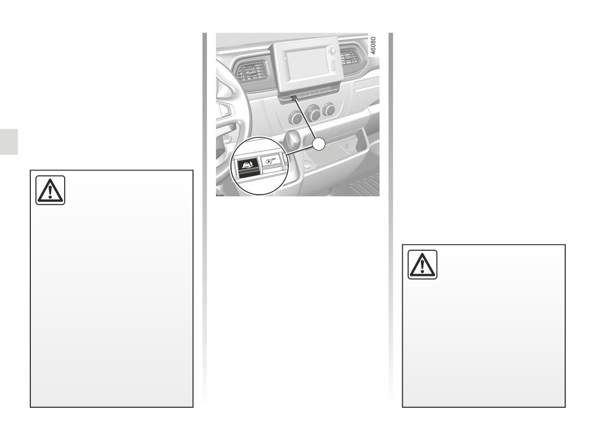
Grip control
The system automatically switches to
“Road” mode at speeds above about
If fitted on the vehicle, grip control
31 mph (50 km/h). The message
makes it easier to control the vehicle on
“Standard road mode on” is displayed
low grip surfaces (soft ground, etc.).
on the instrument panel to warn you.
4
These functions are an ad-
ditional aid in the event of
critical driving conditions,
Press the 4 switch: the message “Grip
enabling the vehicle behav-
Extend Loose Surface ON” is displayed
iour to be adapted to suit the driving
on the instrument panel.
conditions.
This position enables optimal usage on
The functions do not take the place
soft ground (mud, sand, dead leaves,
Tyres
of the driver. They do not increase
etc.). In this position, engine speed is
the vehicle’s limits and should
When they need to be re-
left under the driver’s control.
not encourage you to drive more
placed, only tyres of the
quickly. Therefore, they can under
same make, size, type and
no circumstances replace the vigi-
profile should be used.
lance or responsibility of the driver
Tyres fitted to the vehicle should
when manoeuvring the vehicle (the
either be identical to those fitted
driver must always be ready for
originally or conform to those
sudden incidents which may occur
recommended by your approved
when driving).
dealer.
2.28
CarManuals2.co

DRIVING CORRECTION DEVICES AND AIDS (6/6)
Hill start assistance
Depending on the gradient of the in-
cline, this system assists the driver
when starting on a hill. It prevents the
vehicle from rolling backwards
(de-
The hill start assistance
pending on the gradient of the incline)
system cannot completely
by automatically applying the brakes
prevent the vehicle from
when the driver lifts their foot off the
rolling backwards in all sit-
brake pedal to press the accelerator
uations (extremely steep gradients
pedal.
etc.).
System operation
In all cases, the driver may depress
It only operates when the gear lever is
the brake pedal to prevent the vehi-
in a position other than neutral and the
cle from rolling backwards.
vehicle is completely stationary (brake
The hill start assistance function
pedal depressed).
should not be used for prolonged
The system holds the vehicle for ap-
stops: use the brake pedal.
proximately 2 seconds. The brakes are
This function is not designed to im-
then gradually released (the vehicle will
mobilise the vehicle permanently.
move according to the slope).
If necessary, use the brake pedal to
stop the vehicle.
The driver must remain particularly
vigilant when driving on slippery or
low-grip surfaces.
Risk of serious injury.
2.29
CarManuals2.co
ACTIVE EMERGENCY BRAKING (1/6)
Depending on the reactivity of the
driver, the system can assist with brak-
ing in order to limit damage or prevent
a collision.
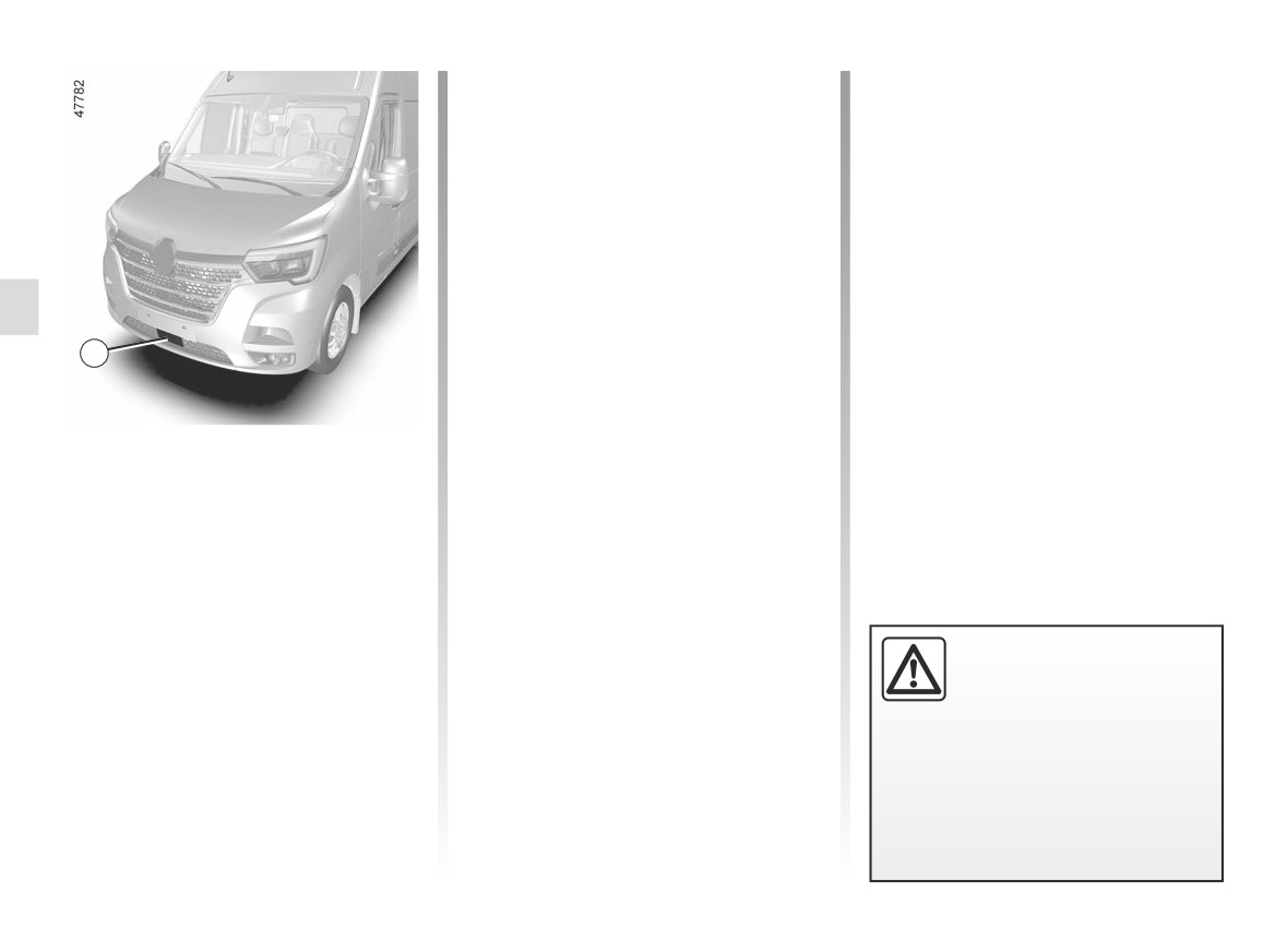
Location of the radar 1
Ensure that the radar area is not ob-
structed (by dirt, mud, snow, a badly
fitted front number plate), impacted,
modified (including painting) or hidden
by any accessory fitted on the front of
1
the vehicle (on the grille or logo etc.).
Using information from the radar 1, the
system calculates the distance which
separates it from the vehicle in front.
The system informs the driver if there
is a risk of head-on collision to enable
appropriate emergency manoeuvres
(pressing the brake pedal and/or turn-
ing the steering wheel).
This function is an addi-
tional driving aid. This func-
tion is not under any circum-
stances intended to replace
the due care and attention of the
driver, who should at all times be
in control of the vehicle.
2.30
CarManuals2.co

ACTIVE EMERGENCY BRAKING (2/6)
Operation
If the vehicle stopped as a result of
Special features of stationary
active emergency braking, the driver
vehicles
Detection of vehicles
must keep the vehicle stationary by ap-
Stationary vehicles are detected when
When driving at a speed between ap-
plying the brake pedal.
your vehicle is being driven at a speed
proximately 3 mph (5 km/h) and 87 mph
Note: if the driver uses the vehicle con-
between approximately 3 mph (5 km/h)
(140 km/h), if there is a risk of collision
trols (steering wheel, pedals, etc.) the
and 68 mph (110 km/h). The system is
with the vehicle in front, the system:
system may delay certain operations or
not active and does not emit a warning
- warns you of a collision risk:
not activate.
for stationary vehicles when your ve-
hicle speed exceeds approximately
the
warning light flashes on
68 mph (110 km/h).
the instrument panel and a beep
sounds.
If the driver presses the brake pedal
and the system still detects a risk
of collision, the
warning light
continues to flash on the instrument
panel, accompanied by a beep, until
the system no longer detects any risk
of collision.
- The following situations may trig-
ger braking:
if the driver fails to react following
the alert and collision becomes im-
minent.
Depending on the vehicle speed,
In the event of emergency manoeu-
the system only detects vehicles
vre, you can stop braking at any
driving in the same direction of traf-
moment by:
fic or at a standstill. The system may
- tapping the accelerator pedal;
not detect motorcycles because of
or
the difficulty in forecasting their tra-
- turning the steering wheel as a
jectory.
collision avoidance manoeuvre.
2.31
CarManuals2.co
ACTIVE EMERGENCY BRAKING (3/6)
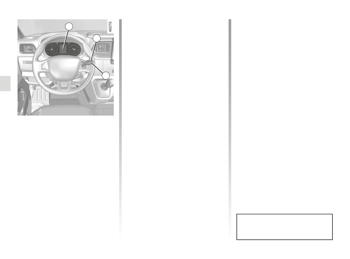
2
Constant illumination of the
warning light on the instrument panel
3
confirms that the system is deactivated.
Pressing and holding button 3 or 4
again will reactivate the system. The
warning light
goes out on the in-
strument panel.
4
Activating/deactivating the
system
With the vehicle stationary and the ig-
nition on:
- repeatedly press button 3 or 4 to
select the “Active braking” function
on the 2 display;
- press and hold button 3 or 4 (for
around three seconds) to deactivate
the system.
Constant illumination of the
warning light on the instrument panel
confirms that the system is deactivated.
This system is reactivated each time
the ignition is switched on.
2.32
CarManuals2.co

ACTIVE EMERGENCY BRAKING (4/6)
Temporarily not available
Operating faults
When the system detects that the func-
If the warning lights
and
tion is temporarily unavailable, the
are illuminated on the instrument
warning light lights up on the
panel accompanied by the message
instrument panel and stays on, accom-
“Check Active braking” this indicates
panied by the message “Front radar no
a system fault. Consult an approved
visibility”.
dealer.
There are two possibilities:
- the system is temporarily disrupted
(for example: radar obscured by
dirt, mud, snow etc.). In this case,
park the vehicle and switch off the
engine. Clean the detection zone of
the radar. When you next start the
engine, the warning light and the
message go out;
- if this is not the case, this may arise
from another cause; contact an
Approved Dealer.
2.33
CarManuals2.co

ACTIVE EMERGENCY BRAKING (5/6)
Active emergency braking
This function is an additional driving aid. This function is not under any circumstances intended to replace the due care
and attention of the driver, who should at all times be in control of the vehicle. The triggering of this function may be
delayed or prevented when the system detects clear signs of control of the vehicle by the driver (action on the steer-
ing wheel, pedals etc.).
The system cannot be activated:
- when the gearbox lever is in neutral or the clutch pedal has been depressed during approximately ten seconds;
- when the parking brake is activated;
- when the Electronic Stability Program (ESC) has started;
- while cornering.
System servicing/repairs
- In the event of an impact, the sensor alignment may become changed, and its operation will consequently be affected.
Deactivate the function, then consult an authorised dealer.
- Any work in the area where the radar is located (repairs, replacements, touching up of paintwork) must be carried out by a
qualified professional.
Only an authorised dealer is qualified to service the system.
2.34
CarManuals2.co

ACTIVE EMERGENCY BRAKING (6/6)
System disturbance
Some conditions can disturb or damage the operation of the system, such as:
- a complex environment (metal bridge, tunnel etc.);
- poor weather conditions (snow, hail, black ice etc.);
- ...
In these conditions, the system may not react or may brake inadvertently.
Limitation of the system operation
- Each time the vehicle is started, the system carries out a calibration according to the vehicle surroundings and may be in-
active for a length of time between approximately two to five minutes.
- A vehicle travelling in the opposite direction will not trigger any alert or any action on the system operation.
- The sensor area should be kept clean and free of any modifications in order to ensure the proper operation of the system.
- The system cannot respond to small vehicles such as motorbikes or bicycles as effectively as to other vehicles.
In these conditions, the system may not react or may brake inadvertently.
Deactivating the function
You must disable the function if:
- the brake lights are not functioning;
- the front of the vehicle has received an impact or has been damaged;
- the vehicle is being towed (breakdowns).
In the event of the system behaving abnormally, deactivate it and consult an authorised dealer.
Halting the function
You can halt the active emergency braking function at any time by tapping the accelerator pedal or by turning the steering
wheel in an avoidance manoeuvre.
2.35
CarManuals2.co
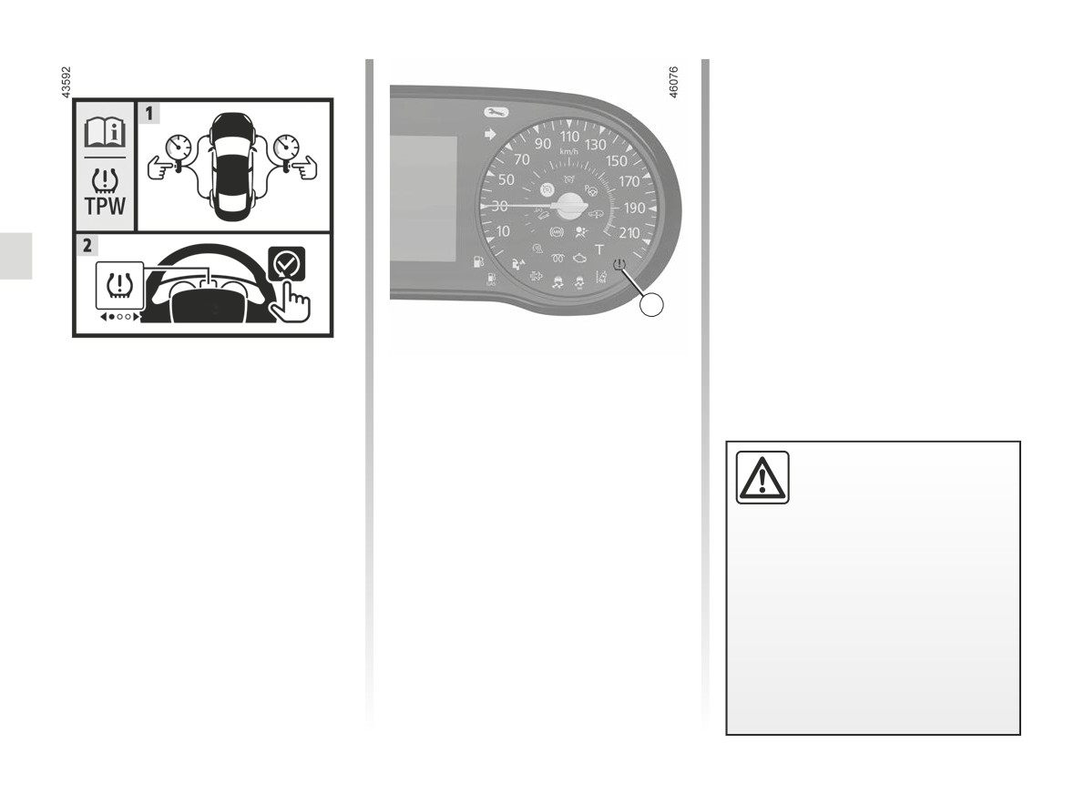
TYRE PRESSURE LOSS WARNING (1/3)
- after changing a wheel.
It should always be done after checking
the tyre pressure of all four tyres when
cold.
Tyre pressures must correspond to the
current usage of the vehicle (empty,
carrying a load, motorway driving, etc.).
1
This system detects a loss of pressure
Resetting the standard level
in one of the tyres by measuring the
for the tyre pressures
wheel speed while driving.
This should be done:
- when the standard tyre pressure
Operating principle
This function is an addi-
needs to be changed to adapt to
tional driving aid.
Warning light
1 comes on to
usage conditions (empty, carrying a
alert the driver in the event of insuffi-
load, motorway driving etc.);
However, the function does
cient pressure (deflated wheel, punc-
not take the place of the
- after swapping a wheel (however
tured tyre, etc.).
driver. It cannot, therefore, under
this practice is not recommended);
any circumstances replace the vig-
ilance or the responsibility of the
driver.
Check the tyre pressures, including
the emergency spare wheel, once a
month.
2.36
CarManuals2.co
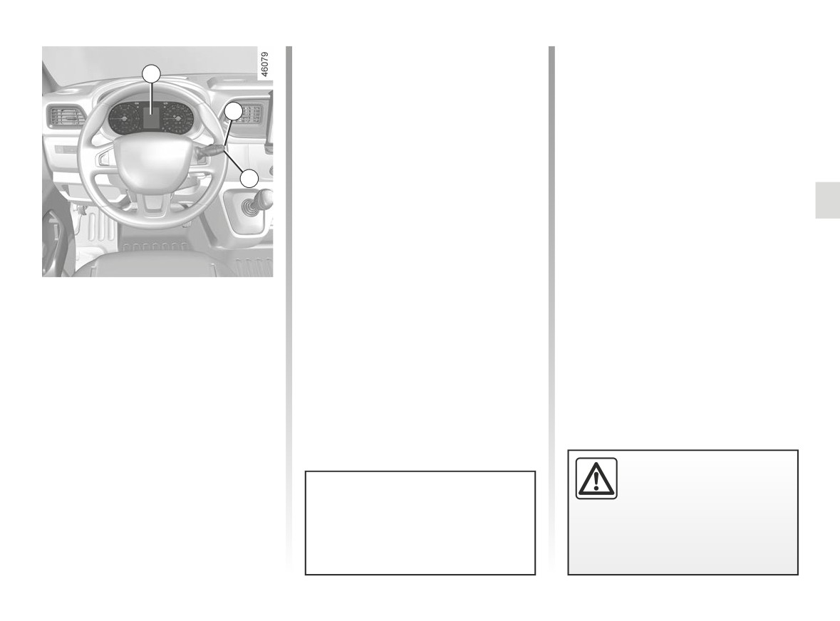
TYRE PRESSURE LOSS WARNING (2/3)
Note: the standard tyre pressure
“Check Tyre Pressure Sensors”
cannot be less than that recommended
2
and indicated on the door frame.
The warning light
comes on
steady, accompanied by the message
3
“Check Tyre Pressure Sensors” and a
Display
beep.
Display 2 on the instrument panel in-
This message appears along with the
forms you of any tyre pressure faults
®
warning light.
(flat tyre, punctured tyre, etc.).
4
They indicate that at least one wheel
“Tyre pressure init. long press”
is punctured or severely underinflated.
Replace it or contact an approved
Warning light
comes on, along
dealer if it is punctured. Top up the tyre
with the message “Tyre pressure init.
pressure if the wheel is deflated.
long press”.
These indicate that at least one tyre is
Resetting procedure
flat.
Ignition on, vehicle stationary:
Check and, if necessary, readjust the
– repeatedly press one of the but-
pressures of the four wheels when cold.
tons 3 or 4 to select the “Tyre pres-
sure init. long press” function on the
The warning light
goes off after a
display 2;
few minutes’ driving.
– press and hold (around 3 seconds)
button 3 or 4 to start initialisation.
Display of the message “Learning
Tyre Pressures” indicates that the
reset request for the tyre pressure
reference value has been taken into
account.
Warning light
®
re-
Reinitialisation is carried out after a few
quires you to stop immedi-
minutes’ driving.
ately, for your own safety,
The sudden loss of pressure in a
as soon as traffic conditions
tyre (burst tyre, etc.) cannot be de-
allow.
tected by the system.
2.37
CarManuals2.co

TYRE PRESSURE LOSS WARNING (3/3)
“Check Tyre Pressure Sensors”
Replacing wheels/tyres
Tyre repair product and
This system requires specific equip-
inflation kit
The warning light
flashes for sev-
ment (wheels, tyres, hubcaps, etc.)
As the valves are specifically designed,
eral seconds, then stays on, along with
➥ 5.18.
only use equipment approved by the
the message “Check Tyre Pressure
approved network. ➥ 5.5 .
Sensors”.
Contact an Approved Dealer to replace
the tyres and to find out about acces-
This message appears along with the
sories compatible with the system and
warning light.
available from your dealer network: the
They indicate that at least one tyre is
use of any other accessory could affect
not fitted with sensors (e.g. emergency
the correct operation of the system.
spare wheel). Otherwise, consult an
authorised dealer.
Emergency spare wheel
If the vehicle is equipped with an emer-
Readjustment of tyre
gency spare wheel, it will not have a
pressures
sensor. When it is fitted on the vehicle,
The tyre pressures must be adjusted
the warning light
flashes for sev-
when cold (please refer to the label lo-
eral seconds, then stays on, together
cated on the edge of the driver’s door).
with the warning light
and
If tyre pressures cannot be checked
the message “Check Tyre Pressure
when the tyres are cold, the recom-
Sensors” appears on the instrument
mended pressures should be increased
panel.
by 0.2 to 0.3 bar (3 PSI).
Never deflate a hot tyre.
Changing a wheel
The system may take sev-
eral minutes depending on
use for the new wheel pres-
sures to be recognised; check the
tyre pressures after all operations.
2.38
CarManuals2.co
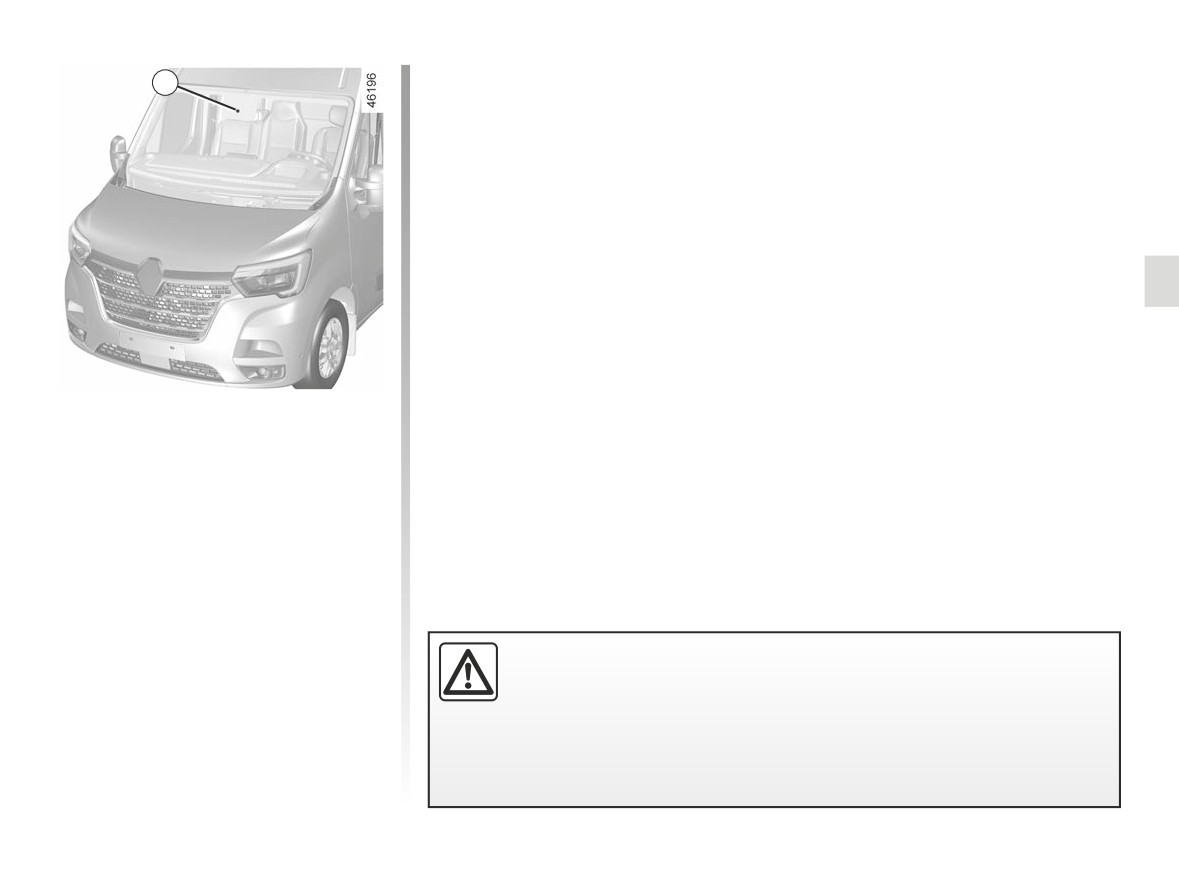
LANE DEPARTURE WARNING (1/4)
Location of the camera 1
1
Make sure the windscreen is not ob-
scured (by dirt, mud, snow, condensa-
tion etc.).
Using information from the camera 1,
the function warns the driver if he
crosses a continuous or broken line
without activating the direction indica-
tor lights.
This function is an additional driving aid. This function is not under any
circumstances intended to replace the due care and attention of the
driver, who should at all times be in control of the vehicle.
The lane departure warning function does not correct the vehicle’s
trajectory.
2.39
CarManuals2.co
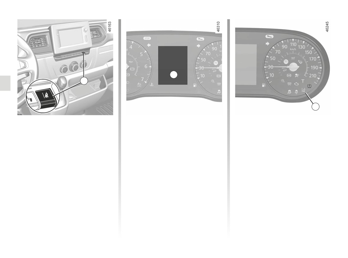
LANE DEPARTURE WARNING (2/4)
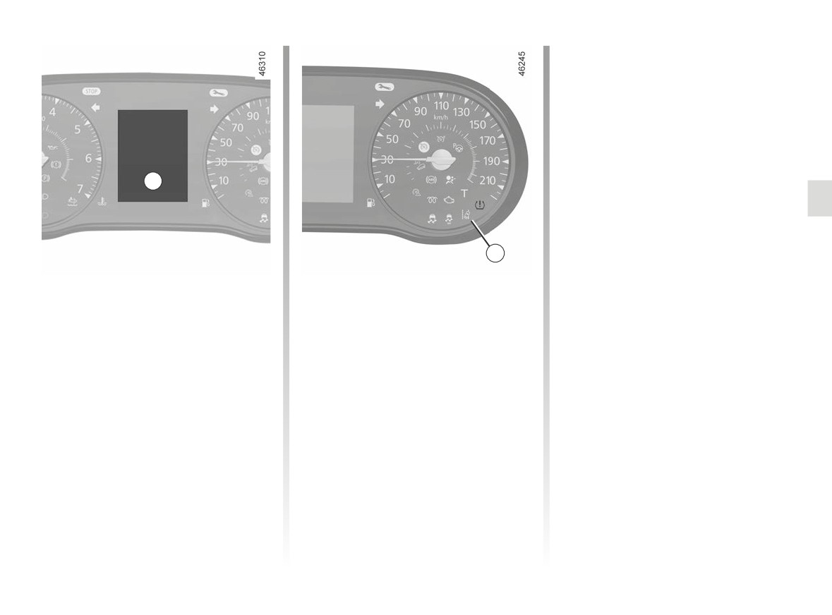
A
2
3
With the ignition on, the function is acti-
To activate the function, press the 2
Operation
vated by default.
switch:
The function is set to notify the
- the message “Lane departure warn-
driver if:
Deactivating/Activating the
ing on” is displayed on the instru-
- the vehicle speed is greater than ap-
ment panel A;
function
proximately 37 mph (60 km/h);
To deactivate it, press the 2 switch:
- the
warning light is displayed
and
- the message “Lane departure warn-
in grey on the instrument panel A.
- lines are detected.
ing off” is displayed on the instru-
ment panel A;
The
warning light is displayed
in white on the instrument panel A to
- the
warning light disappears
notify the driver.
from the instrument panel A and is
displayed in orange underneath the
speedometer 3.
2.40
CarManuals2.co
LANE DEPARTURE WARNING (3/4)
Conditions for non-activation
of the system
The system cannot be activated when:
- the vehicle speed is less than ap-
proximately 37 mph (60 km/h);
- reverse gear is engaged;
- the field of vision of the camera is ob-
structed;
A
- the û
warning light is displayed.
The
warning light is displayed in
grey on the instrument panel A.
3
Operating faults
Operation (continued)
Temporarily not available
In the event of a malfunction:
The function triggers an alert if a line
- Very fast lane departure;
- the
warning light disappears;
is crossed without the direction indica-
- driving continuously on a line;
tors being activated.
- four seconds approximately after
- the “Lane Departure Warning Check”
changing lanes;
message is displayed on the instru-
The function alerts the driver:
- tight bends;
ment panel A along with the warning
- by emitting a beep;
- impaired visibility;
and
- activation of one of the direction indi-
Consult an approved dealer.
cator lights;
– strong acceleration;
- the
warning light flashes in
- ...
white on the instrument panel A.
When the function is not available, the
warning light is displayed in grey
on the instrument panel A.
2.41
CarManuals2.co

LANE DEPARTURE WARNING (4/4)
This function is an additional driving aid. This function is not under any circumstances intended to replace the due care
and attention of the driver, who should at all times be in control of the vehicle.
System servicing/repairs
- In the event of an impact, the camera alignment may be changed, and its operation may consequently be affected. Deactivate
the function, then consult an authorised dealer.
- Any work in the area where the camera is located (repairs, replacements, windscreen modifications etc.) must be carried
out by a qualified professional.
Only an authorised dealer is qualified to service the system.
In the event of system disturbance
Some conditions can disrupt or damage the operation of the system, for example:
- a complex environment (tunnel etc.);
- poor weather conditions (snow, hail, black ice etc.);
- poor visibility (night, fog etc.);
- road markings which are worn, lacking in contrast or very widely spaced from one another (lines partially erased etc);
- being dazzled (glaring sun, lights of vehicles travelling in the opposite direction etc.);
- the road is narrow, winding or undulating (tight bends etc.);
- closely following a vehicle travelling in the same lane.
Risk of false alarms or absence of warnings
2.42
CarManuals2.co
BLIND SPOT WARNING (1/6)
1
A
A
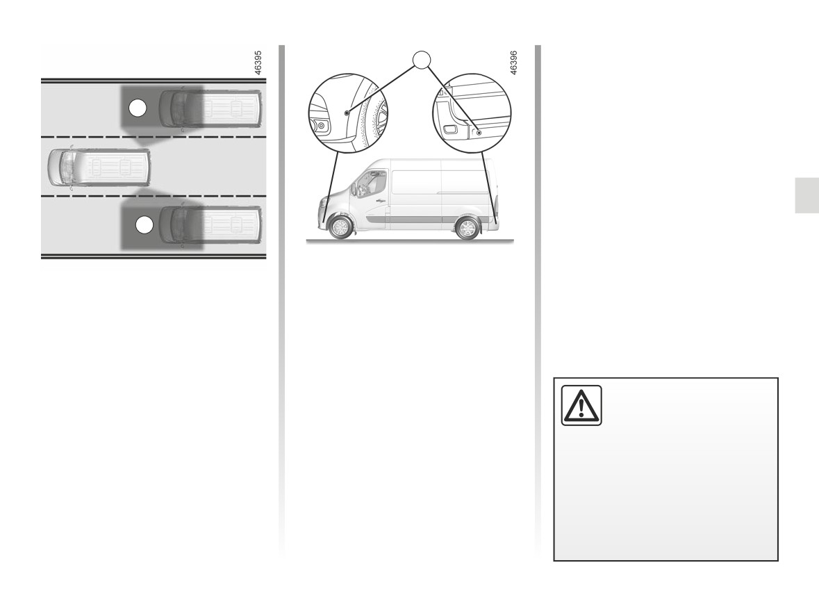
Using information from the sensors 1
Special feature
installed on each side of the rear
Make sure that the 1 sensors are not
bumper, the system notifies the driver
obscured (by dirt, mud, snow, etc.).
when another vehicle appears in detec-
tion zone A.
If a sensor is obscured, the message
“Blind spot clean sensor” will appear on
The system is activated when the ve-
the instrument panel. Clean the sen-
hicle’s speed is between approximately
sors.
19 mph
(30 km/h) and
87 mph
This function is an addi-
(140 km/h).
tional driving aid.
This function is not under
any circumstances in-
tended to replace the due care and
attention of the driver, who should at
all times be in control of the vehicle.
2.43
CarManuals2.co
BLIND SPOT WARNING (2/6)
4
B
5
C
4
2
3
D
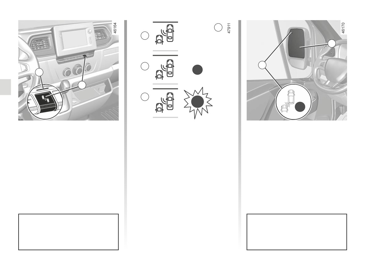
Deactivation/activation
Indicator 4
Operation
Press 3 to deactivate the function.
An indicator light 4 is located on each
This function gives a warning:
Warning light 2 comes on.
rear view mirror 5.
- when the vehicle speed is between
Pressing again reactivates the function.
Note: clean the rear view mirrors 5 reg-
approximately 19 mph (30 km/h) and
Le warning light 2 disappears and the
ularly so that the indicators 4 can be
87 mph (140 km/h);
message “blind spot alert activated” is
seen.
and
displayed on the instrument panel.
- when another vehicle is in the blind
spot area A and travelling in the
same direction as your vehicle.
When the engine is started, the
The function does not notify the
system remembers its last recorded
driver if the other vehicles are not
position when the ignition was last
moving.
switched off.
2.44
CarManuals2.co
BLIND SPOT WARNING (3/6)
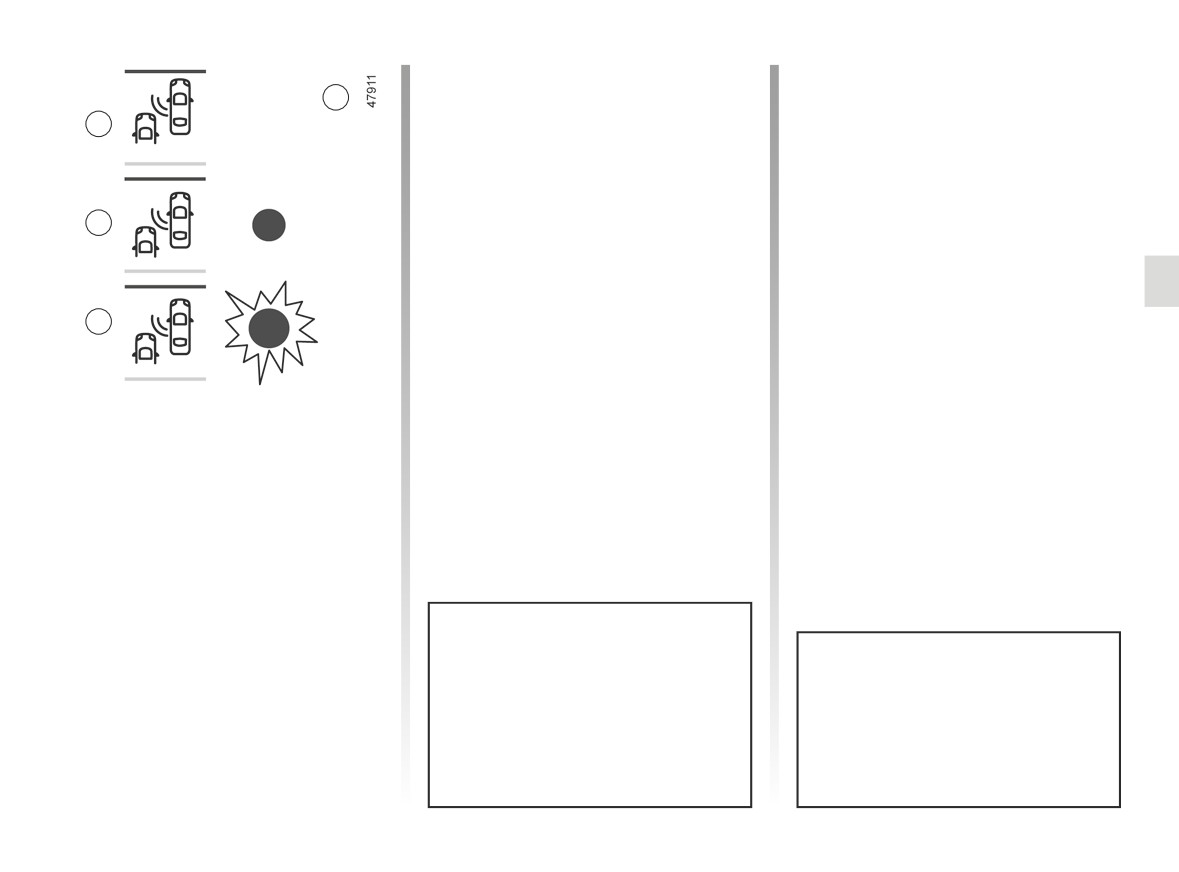
Display B
Conditions for non-function
4
The function is activated and has not
- If the object is not moving;
B
detected any vehicles.
- if traffic is heavy;
- the road is winding;
- if front and rear sensors both detect
Display C
an object at the same time (e.g.
First warning: when the direction in-
when passing an articulated lorry).
C
dicator is not activated, the 4 warning
- ...
light signals that a vehicle is detected in
If the vehicle is equipped with a towbar
the blind spot.
recognised by the system, the mes-
sage “Trailer: blind spot warning OFF”
D
Display D
is displayed on the instrument panel in-
forming you that the function is not op-
When the direction indicator is acti-
erational. For information on the range
vated, the 4 warning light flashes if a
of equipment adapted to your vehicle,
vehicle is detected in the blind spot on
If you overtake another vehicle, the in-
we advise you to consult an approved
the side towards which you are about to
dicator 4 will only come on if that vehi-
Dealer.
steer. If you cancel the direction indica-
cle remains for a long enough period in
tor, the function will return to the initial
your vehicle’s blind spot A .
warning (display C).
The system’s detection range oper-
ates according to a standard lane
Due to the presence of sensors in
width. When driving in a narrow
the bumper, it is advisable to en-
lane, the function may warn you
trust any operation on the bumper
when a vehicle is detected further
(repair, replacement, paintwork,
away than the nearest lane.
etc.) to a qualified professional.
2.45
CarManuals2.co
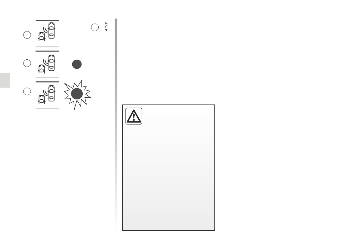
BLIND SPOT WARNING (4/6)
4
B
C
D
-The system’s detection
Operating faults
range operates according
to a standard lane width. If
If the system detects a fault, the mes-
you are driving in wide traf-
sage “Check blind spot alert” is dis-
fic lanes, the system might not
played on the instrument panel. Call an
be able to detect a vehicle in the
approved Dealer.
blind spot.
Note: when the engine is started, the
- The system might be disrupted
indicator light
4, display B, flashes
momentarily if it is exposed to
three times. It is normal.
strong electromagnetic waves
(as beneath high-tension power
lines) or to very poor weather
conditions
(heavy rain, snow
etc.). Remain aware of driving
conditions.
There is a risk of accidents.
2.46
CarManuals2.co

BLIND SPOT WARNING (5/6)
This function is an additional driving aid. This function is not under any circumstances intended to replace the due care
and attention of the driver, who should at all times be in control of the vehicle.
The driver should always adapt their speed to the traffic conditions, regardless of the system indications.
The system should under no circumstances be taken to be an obstacle detector or an anti-collision system.
System servicing/repairs
- In the event of an impact, the alignment of the sensors may be changed and its operation may consequently be affected.
Deactivate the function and consult an authorised dealer.
- Any work in the area where the sensors are located (repairs, replacements, etc.) must be carried out by a qualified profes-
sional.
Only an authorised dealer is qualified to service the system.
System disturbance
Some conditions can disrupt or damage the operation of the system, for example:
- complex surroundings (metal bridges, tunnels, roads with barriers at the edge, etc.);
- poor weather conditions (snow, hail, black ice, etc.).
Risk of false alarms or absence of warnings
In the event of the system behaving abnormally, deactivate it and consult an authorised dealer.
2.47
CarManuals2.co

BLIND SPOT WARNING (6/6)
Limitation of the system operation
- The area around the sensors should be kept clean and free of any modifications in order to ensure the proper opera-
tion of the system.
- Small objects moving close to the vehicle (motorcycles, bicycles, pedestrians, etc.) may not be recognised by the system.
- When turning into a bend, the radars may temporarily cease to detect vehicles in adjacent lanes.
- The system may not provide a warning when the other vehicles are travelling at a significantly different speed.
- The vehicle is travelling on a winding road.
Deactivating the function
You must disable the function if:
- the area around the sensors has been damaged;
- the vehicle is fitted with a towbar that is not recognised by the system.
2.48
CarManuals2.co
SPEED LIMITER (1/3)
The speed limiter function helps you
stay within the driving speed limit that
you choose, known as the limit speed.
6
1
2
3
4
5
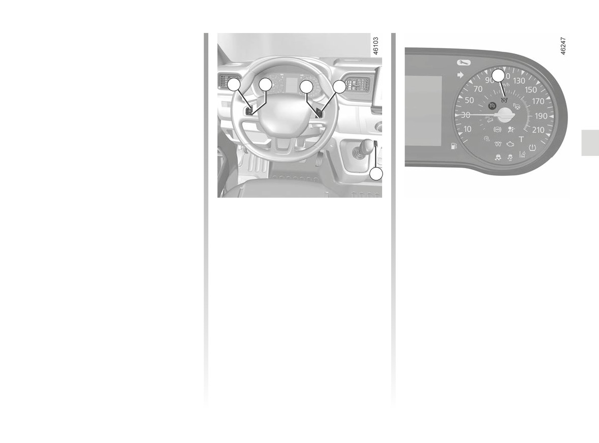
Controls
Switching on
1 Speed limiter activation, memory
Press the side switch 5 . The warn-
and increase (+).
ing light 6 comes on, lit orange, and the
2 Decrease limit speed (-).
message “SPEED LIMITER” appears
3 Speed limiter function standby (with
on the instrument panel, accompanied
limited speed memory) (O).
by dashes to indicate that the speed
4 Activation and recall of memorised
limiter is activated and waiting to store
limit speed (R).
a speed limit.
5 Main “On/Off” switch.
To store the current speed, press
switch 1 (+): the limited speed replaces
the dashes.
The minimum stored speed is 19 mph
(30 km/h).
2.49
CarManuals2.co
SPEED LIMITER (2/3)
Varying the limit speed
Exceeding the limit speed
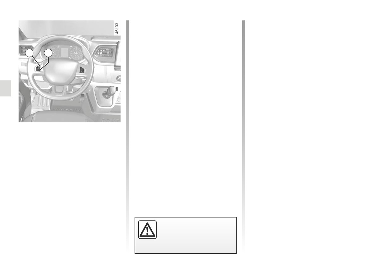
The limit speed may be changed by re-
It is possible to exceed the limit speed
peatedly pressing:
at any moment. To do this: press the
accelerator pedal firmly and fully
-
switch 1 (+) to increase speed;
1
2
(beyond the kickdown point).
-
switch 2 (-) to reduce speed.
If the speed is exceeded, the limited
speed flashes on the instrument panel
accompanied by a beep.
Then, as far as is possible, release
the accelerator pedal: the speed lim-
iter function will return as soon as you
reach a speed lower than the memo-
rised speed.
Limited speed cannot be maintained
Driving
When driving down a steep gradient,
When a limited speed has been stored
the system is unable to maintain the
and this speed is not reached, driving is
limit speed: the memorised speed will
similar to driving a vehicle without the
flash on the instrument panel and an
speed limiter function.
audible signal sounds at regular inter-
vals to inform you of this situation.
Once you have reached the stored
speed, no effort on the accelera-
tor pedal will allow you to exceed
the programmed speed except in an
emergency (refer to information on
“Exceeding the limit speed”).
The speed limiter function is
in no way linked to the brak-
ing system.
2.50
CarManuals2.co
SPEED LIMITER (3/3)
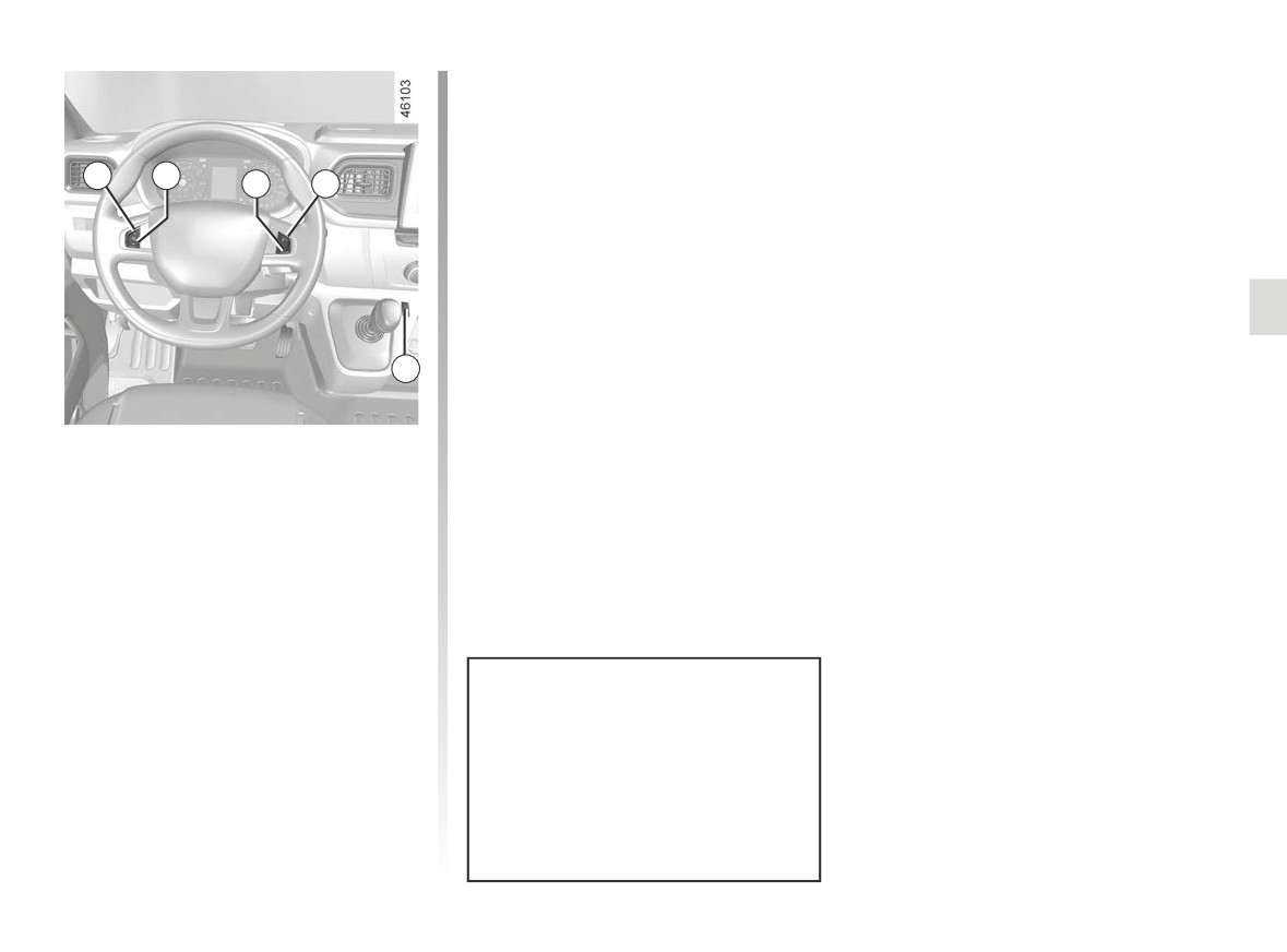
Recalling the limit speed
If a speed has been memorised, it can
be recalled by pressing switch 4 (R).
1
2
3
4
Switching off the function
The speed limiter function is deacti-
vated when you press switch 5. In this
case, the speed is no longer memo-
rised. The instrument panel orange in-
dicator light goes out, confirming
that the function is deactivated.
5
Putting the function on
standby
The speed limiter function is suspended
when you press switch 3 (O). In this
case, the speed limit remains stored
and the message “Memorisedˮ, accom-
panied by this speed, appears on the
instrument panel.
When the speed limiter is set to
standby, pressing switch 1 (+) re-
activates the function without taking
into account the memorised speed:
it is the speed at which the vehicle
is moving that is taken into account.
2.51
CarManuals2.co
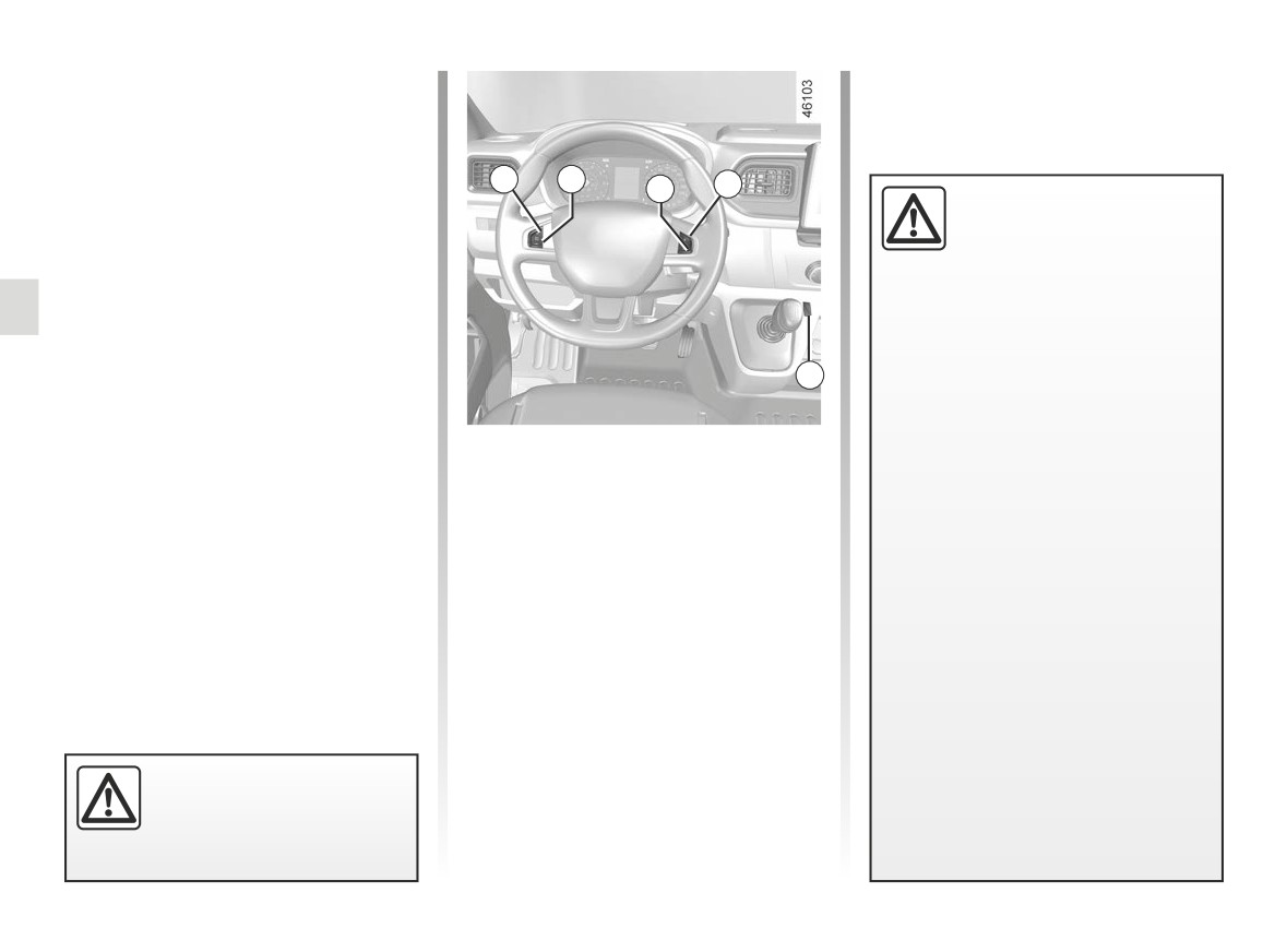
CRUISE CONTROL (1/4)
The cruise control function helps you to
maintain your driving speed at a speed
that you choose, called the cruising
speed.
This cruising speed may be set at any
1
2
3
4
speed above 19 mph (30 km/h).
This function is an addi-
tional driving aid. It can
under no circumstances re-
place the driver’s responsi-
bility to respect speed limits or to be
vigilant.
The driver must always be in control
of the vehicle.
5
Therefore, it can under no circum-
stances replace the driver’s respon-
Controls
sibility to respect speed limits and to
be vigilant (the driver must always
1 Cruising speed activation, storage
be ready to brake).
and increase switch (+).
Cruise control must not be used in
2 Decreasing cruising speed (-).
heavy traffic, on undulating or slip-
3 Switch the function to standby (with
pery roads (black ice, aquaplan-
cruising speed saved) (0).
ing, gravel) and during bad weather
(fog, rain, side winds etc.).
4 Activation with recall of saved cruis-
ing speed (R).
There is a risk of accidents.
5 Main “On/Off” switch.
The cruise control function
is in no way linked to the
braking system.
2.52
CarManuals2.co
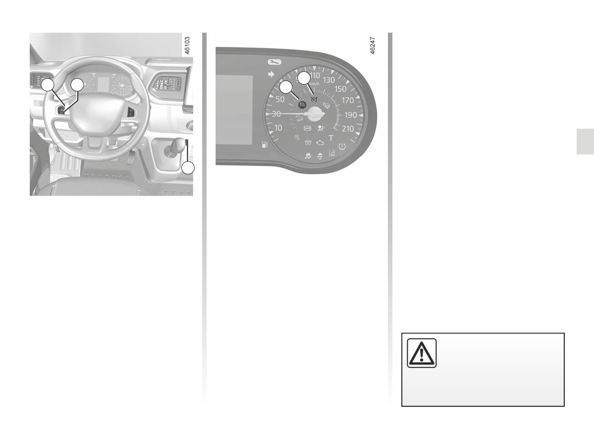
CRUISE CONTROL (2/4)
Driving
Once a cruising speed is memorised
and the cruise control function is active,
you may lift your foot off the accelera-
6
1
2
tor pedal.
7
5
Switching on
Activating cruise control
Press switch 5 on the side showing .
At a steady speed over approximately
18 mph (30 km/h) press the switch 1 (+)
Indicator light 6 comes on, lit green,
or 2 (-): the function is activated and the
and the message “Cruise Control” ap-
current speed is stored.
pears on the instrument panel, accom-
panied by dashes to indicate that the
The cruising speed replaces the dashes
cruise control function is activated and
and the cruise control is confirmed by
waiting to store a cruising speed.
the appearance of warning light 7 lit
green, as well as warning light 6.
Please note that you must
keep your feet close to the
pedals in order to react in
an emergency.
2.53
CarManuals2.co
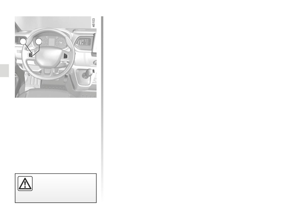
CRUISE CONTROL (3/4)
Exceeding the cruising speed
The cruising speed may be exceeded
at any time by depressing the accelera-
tor pedal. While it is being exceeded,
1
2
the cruising speed flashes on the in-
strument panel.
Then, release the accelerator pedal:
after a few seconds, the vehicle will
automatically return to its set cruising
speed.
Cruising speed cannot be
maintained
When driving down a steep gradient,
the system is unable to maintain the
Adjusting the cruising speed
cruising speed: the stored speed will
flash on the instrument panel informa-
The cruising speed may be changed by
tion display to inform you of this situ-
pressing the following repeatedly:
ation.
- the switch
1 (+) to increase the
speed;
- the switch 2 (-) to reduce the speed.
The cruise control function
is in no way linked to the
braking system.
2.54
CarManuals2.co
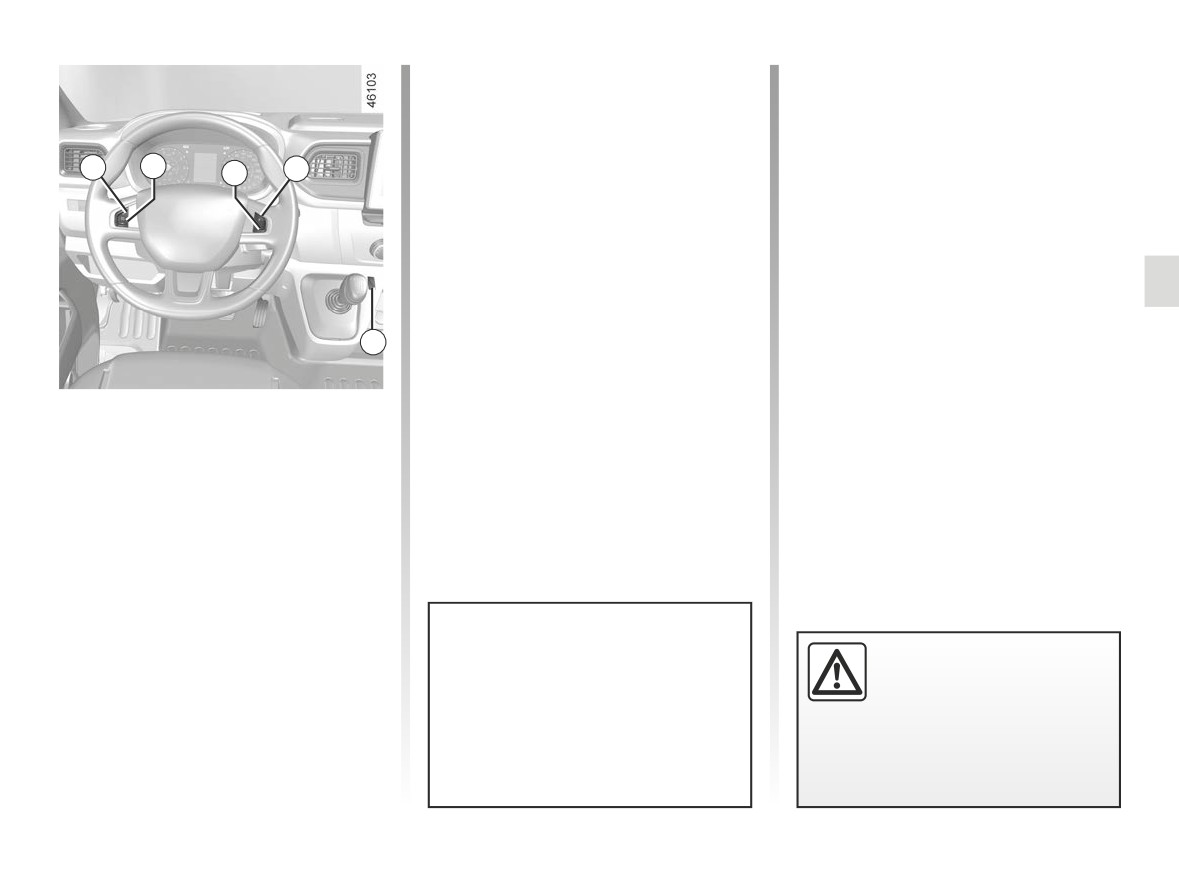
CRUISE CONTROL (4/4)
Recalling the cruising speed
Switching off the function
If a speed is stored, it can be recalled,
The cruise control function is deacti-
once you are sure that the road condi-
vated when you press the 5 switch. In
tions are suitable (traffic, road surface,
this case, the speed is no longer stored.
1
2
4
weather conditions, etc.).
3
The and Ï
indicator lights on
Press the switch 4 (R) if the vehicle
the instrument panel go out, confirming
speed is above 19 mph (30 km/h).
that the function is deactivated.
When recalling the stored speed, acti-
vation of the cruise control is confirmed
by the indicator light Ï
coming on.
Note: if the speed previously stored is
5
much higher than the current speed,
the vehicle will accelerate more rapidly
to reach this threshold.
Putting the function on
standby
The function is set to standby if you:
- the button 3 (0);
- the brake pedal;
- the clutch pedal or shift into neutral if
the vehicle is fitted with a sequential
gearbox.
In all three cases, the cruising speed
remains stored and the message
“Memorised” appears on the instrument
When the cruise control is set to
Putting the cruise control
panel.
standby, pressing the switch 1 (+)
on standby or switching it
Standby is confirmed when the green
reactivates the cruise control func-
off does not cause a rapid
tion without taking into account the
Ï
indicator light goes out.
reduction in speed: you
stored speed: it is the speed at
must brake by depressing the brake
which the vehicle is moving that is
pedal.
taken into account.
2.55
CarManuals2.co
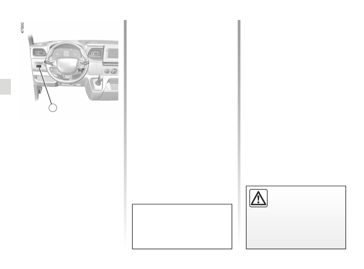
VEHICLE WITH OVERSPEED FUNCTION
Special case: if your vehicle is fitted
with the Cruise control/Speed limiter,
fully pressing the accelerator pedal
(beyond the kickdown point) will not
enable you to exceed the overspeed
function set speed. ➥ 2.49.
1
The vehicle speed may be permanently
set at a fixed value depending on the
vehicle or on local legislation.
To adjust the value or activate/deacti-
vate the function, consult an approved
dealer.
In the event of statutory limits (depend-
ing on the vehicle), this function may
not be deactivated.
Label 1 attached to the dashboard
The function does not take
shows the speed limit.
the place of the driver.
Under no circumstances
should it replace observa-
In exceptional circumstances (e.g.
tion of speed limits nor vigilance
steep gradient), the overspeed
and responsibility on the part of the
function speed may be exceeded
driver.
slightly as the function does not
affect the braking system.
2.56
CarManuals2.co
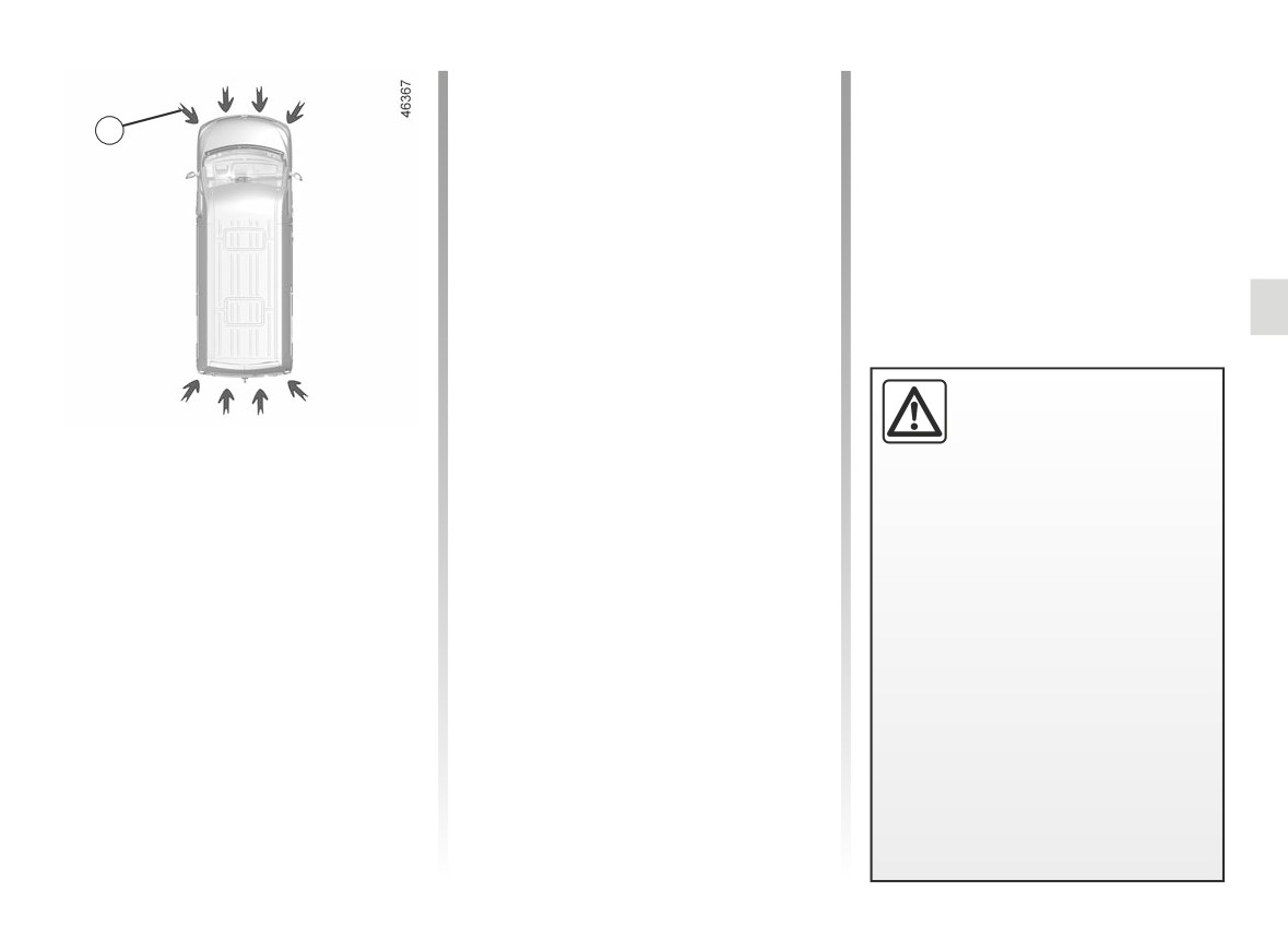
PARKING DISTANCE CONTROL (1/6)
The system detects obstacles to the
front, the rear and the sides of the ve-
hicle.
1
The parking distance control system
is only activated when the vehicle is
driven at a speed below approximately
6 mph (10 km/h).
The function does not take into account
towing or carrying systems that are not
recognised by the system.
Location of the ultrasonic sensors 1
Ensure that the ultrasonic sensors indi-
This function is an addi-
cated by the arrows 1 are not obscured
tional driving aid.
(by dirt, mud, snow, a badly fitted/at-
Operating principle
tached number plate), impacted, mod-
Under no circumstances
ified (including paintwork) or obstructed
should it replace the driv-
Ultrasonic sensors, indicated by the
by any accessory fitted to the rear and/
er’s care or responsibility whilst re-
arrows 1, are fitted in the rear bumper
or, depending on the vehicle, to the
versing.
(and in the front bumper, depending on
front or sides of your vehicle.
the vehicle) to measure the distance
The driver should always be ready
between the vehicle and an obstacle.
for sudden incidents while driv-
ing: always ensure that there are
This measurement is indicated by
no small, narrow moving obstacles
beeps which become more frequent the
(such as a child, animal, pushchair,
closer you come to the obstacle, until
bicycle, stone, post etc.) in the blind
they become a continuous beep when
spot when manoeuvring.
the vehicle is approximately 30 centi-
metres from the obstacle.
2.57
CarManuals2.co
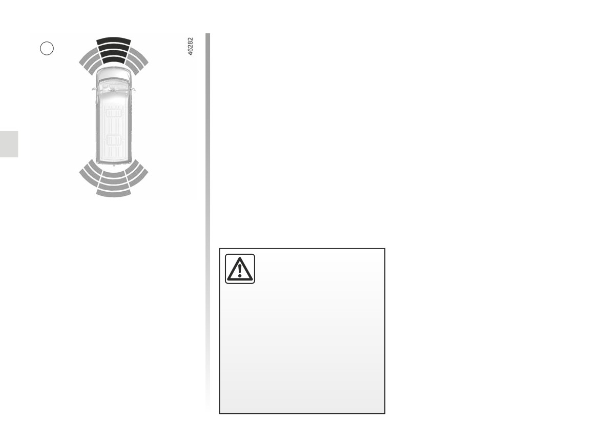
PARKING DISTANCE CONTROL (2/6)
Operation
2
Most objects located near the rear and,
depending on the vehicle, near the front
end are detected.
Depending on the distance of the ob-
stacle, the frequency of the beep will
increase as it approaches and will
become a continuous beep at around
30 cm from an obstacle behind the ve-
hicle or in front of it, depending on the
vehicle. The areas are shown on the 2
display.
Note: in the event of a change in tra-
jectory during a manoeuvre, the risk of
collision with an obstacles may be sig-
Note: the display 2 shows the vehicle
nalled late.
surroundings and emits beeps.
If all areas have a grey background, the
whole area around the vehicle is being
monitored.
An impact to the under-
side of the vehicle while
manoeuvring
(e.g.: strik-
ing a post, raised kerb or
other street furniture) may result in
damage to the vehicle (e.g.: defor-
mation of an axle).
To avoid any risk of accident, have
your vehicle checked by an ap-
proved Dealer.
2.58
CarManuals2.co
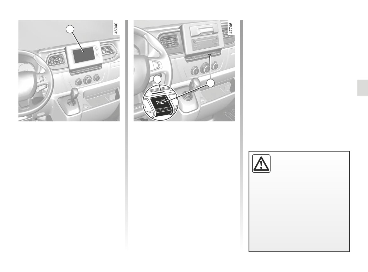
PARKING DISTANCE CONTROL (3/6)
3
4
5
Deactivating the system
Vehicles not fitted with a multimedia
system
Vehicles fitted with a multimedia
With the vehicle stopped, press the 5
system
button to deactivate the system.
On the multimedia screen 3, select
Warning light 4 appears to indicate that
An impact to the under-
the
“SETTINGS” menu followed by
the system is deactivated.
side of the vehicle while
“VEHICLE”, “Parking assistance” then
manoeuvring
(e.g.: strik-
choose “ONˮ or “OFFˮ to activate or de-
Pressing the switch again will reacti-
ing a post, raised kerb or
activate Park Assist.
vate the system and switch off the in-
other street furniture) may result in
dicator light.
damage to the vehicle (e.g.: defor-
mation of an axle).
To avoid any risk of accident, have
your vehicle checked by an ap-
proved Dealer.
2.59
CarManuals2.co

PARKING DISTANCE CONTROL (4/6)
Deactivating the parking
- when the vehicle is in neutral
(manual gearbox) or in N position
distance control manually
(sequential gearbox);
You must disable the function if:
- when an operating fault is detected.
- if towing, carrying or trailer equip-
Note: if the vehicle is fitted with a
ment that is unrecognised by the
towbar recognised by the system, only
system is present in front of the ul-
the rear Park Assist is deactivated.
trasonic sensors;
- in the event of damage to the ultra-
sonic sensors.
Operating faults
Depending on the vehicle, when the
system detects an operating fault, the
Automatic deactivation of the
message “Check Park Assist” appears
parking distance control
on the instrument panel, accompanied
The system is deactivated:
lasting approximately three seconds.
- when the vehicle speed is above ap-
Consult an approved dealer.
proximately 6 mph (10 km/h);
- depending on the vehicle, when the
vehicle is stationary for more than
approximately five seconds and an
obstacle is detected (such as when
in a traffic jam, etc.);
2.60
CarManuals2.co

PARKING DISTANCE CONTROL (5/6)
System servicing/repairs
- In the event of an impact, the alignment of the sensors may be altered and their operation may consequently be affected.
Deactivate the function and consult an authorised dealer.
- Any work in the area where the sensors are located (repairs, replacements, etc.) must be carried out by a qualified profes-
sional.
Only an authorised dealer is qualified to service the system.
System disturbance
Some conditions can disrupt or damage the operation of the system, for example:
- poor weather conditions (rain, snow, hail, black ice, etc.);
- in the event of exposure to strong electromagnetic waves (under high-voltage lines, etc.);
- some types of noise (motorcycle, lorry, pneumatic drill etc.);
- fitting a non-compatible towing ball or hook;
- ...
Risk of false alarms or absence of warnings
In the event of the system behaving abnormally, deactivate it and consult an authorised dealer.
2.61
CarManuals2.co

PARKING DISTANCE CONTROL (6/6)
Limitation of the system operation
- The area around the sensors must be kept clean and free of any modifications in order to ensure the proper operation of the
system.
- Small objects moving close to the vehicle (motorcycles, bicycles, pedestrians, etc.) may not be recognised by the system.
- The system may not detect objects that are too close to the vehicle.
- The system may not provide a warning when the other vehicles or objects are travelling at a significantly different speed.
- When there is a change in trajectory during a manoeuvre, the system may be slow in reporting obstacles.
- When the vehicle is towing a trailer, the rear Park Assist system must be deactivated.
Deactivating the function
You must disable the function if:
- the area around the sensors has been damaged;
- the vehicle is equipped with a towing device that is not recognised by the system (electrical adapter, ball, hook, etc.).
2.62
CarManuals2.co
REVERSING CAMERA (1/3)
3
1
2
Operation
Note: make sure that the reversing
Note: depending on the vehicle, you
camera is not obscured (by dirt, mud,
can adjust certain settings from the
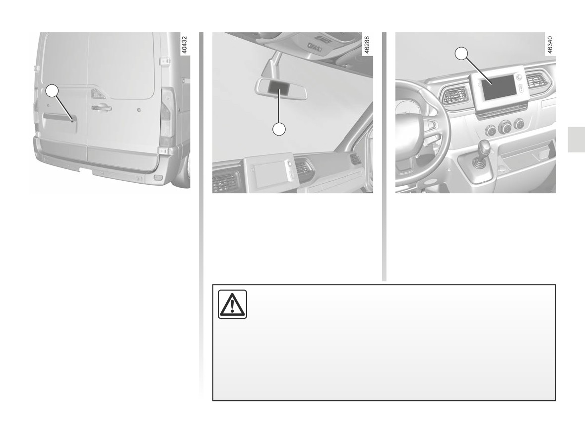
Moving into reverse gear, the camera 1
snow, condensation, etc.).
multimedia display
3. Refer to the
located on the tailgate or, depending
handbook for the equipment.
on the vehicle, on the rear hinged door,
provides a view of the area behind the
vehicle on the rear view mirror 2 or, de-
pending on the vehicle, on the multi-
media display 3, accompanied by two
moving or fixed guide lines 4 and 5.
This function is an additional aid. It cannot, therefore, under any circum-
stances replace the vigilance or the responsibility of the driver.
The driver should always be ready for sudden incidents while driving:
always ensure that there are no small, narrow moving obstacles (such
as a child, animal, pushchair, bicycle, stone, post, etc.) in the blind spot when
manoeuvring.
2.63
CarManuals2.co
REVERSING CAMERA (2/3)
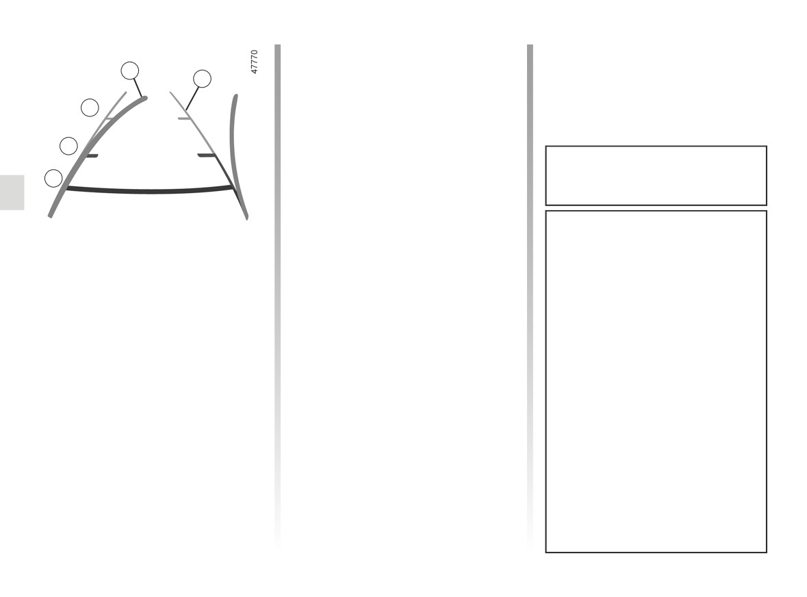
This gauge remains fixed and indicates
the vehicle trajectory if the wheels are
4
5
in line with the vehicle.
This system is initially used with the aid
C
of several gauges (mobile for trajectory
and fixed for distance). When the red
zone is reached, use the bumper image
B
to stop accurately.
The width of the guide lines corre-
A
sponds to the width of the vehicle in-
cluding the door mirrors.
The screen shows a reverse image.
Dynamic gauge 4 (depending on the
The frames are a representation
vehicle)
projected on a flat surface. This in-
This is shown in blue on the multimedia
formation is to not be taken into ac-
display 3. It indicates the vehicle tra-
count when superimposed on a
jectory according to the position of the
vertical object or an object on the
steering wheel.
ground.
Objects which appear on the edge
Static guide line 5:
of the screen may be deformed.
The fixed clearance gauge comprises
coloured markers A, B and C, indicat-
In very bright light (snow, vehicle in
ing the distance behind the vehicle:
sunshine etc.), the camera vision
may be adversely affected.
- A (red) approximately 30 centime-
tres from the vehicle;
If the rear doors are open or poorly
- B (yellow) at approximately 70 centi-
closed, the camera display disap-
metres from the vehicle;
pears and, depending on the vehi-
- C (green) approximately 150 centi-
cle, the message “WARNING: Boot
metres from the vehicle.
Open” appears.
2.64
CarManuals2.co
REVERSING CAMERA (3/3)
H
F
G
J
K
D E
H J K
6
D E
6
F G
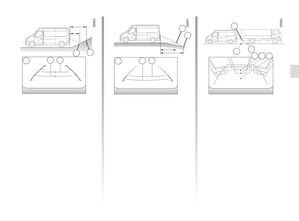
Difference between the
Reversing towards a steep downhill
Reversing towards a protruding
slope
object
estimated distance and
actual distance
The fixed guidelines 6 show the dis-
Position H seems further than position J
tances as further than they actually are.
on the screen. However, position H is at
Reversing towards a steep uphill
the same distance as position K.
Therefore, the objects shown on the
slope
screen are actually closer on the slope.
The trajectory indicated by the fixed
The fixed guidelines 6 show the dis-
and mobile guidelines do not take into
For example, if the screen displays an
tances as closer than they actually are.
account the height of the object. So
object at G, the actual distance of the
there is a risk that the vehicle may col-
The objects shown on the screen are
object is at F.
lide with the object when reversing to-
actually further away on the slope.
wards position K.
For example, if the screen displays an
object at D, the actual distance of the
object is at E.
2.65
CarManuals2.co
POWER TAKE-OFF
Operating faults
Switching off the function
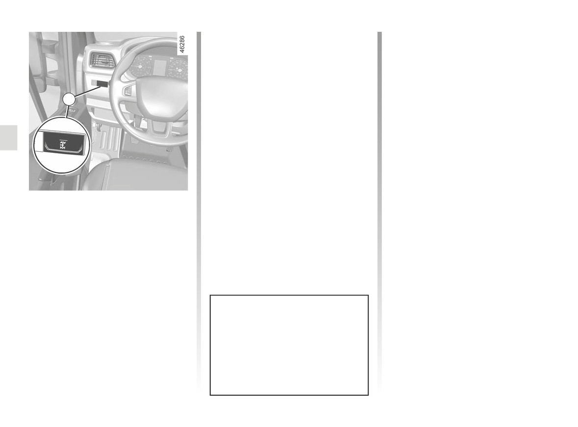
If the warning light incorporated in the 1
- Depress the clutch pedal;
switch does not appear and the power
- press switch 1. The warning light in-
take-off does not start:
corporated in the 1 switch goes out
- with the clutch pedal depressed,
after approximately two seconds.
press switch 1 and release the clutch
1
pedal then repeat the procedure;
- or gradually release the clutch pedal.
Operating the function
With the vehicle stopped, the engine
idling, the gearbox in neutral:
- depress the clutch pedal;
- press switch 1. The warning light in-
corporated in the 1 switch appears;
- release the clutch pedal. The idle
speed increases to 1,200 rpm.
When the power take-off is en-
gaged, do not change gear. If it be-
comes necessary to change gear,
you must first disconnect the power
take-off.
2.66
CarManuals2.co
FAST IDLE SPEED
Switching off the function
The function is interrupted when:
- you depress the clutch pedal and/or
accelerator pedal;
1
- the sequential gearbox is not in neu-
tral;
- the vehicle speed is above 0 mph;
- the
®
indicator light is lit up on
the instrument panel;
- the
indicator light is lit up on
the instrument panel;
- the
Ô
indicator light is lit up on
Press control 1, and the function will be
the instrument panel.
activated after a few seconds.
Modifying fast idle speed
To increase or reduce the speed, con-
tact an approved dealer.
Special feature of the Stop and
Start function: activating the “Fast
Idle Speed” function prevents the
engine from going into standby.
➥ 2.4 .
2.67
CarManuals2.co

SELF-LOCKING DIFFERENTIAL
The self-locking differential controls the
torque transmitted to each rear wheel.
Depending on the grip conditions on
the road surface, and at low speeds
(under 20 mph/30 kph), this device en-
ables wheel torque to move automati-
cally, thereby providing increased grip.
This enables the grip potential of each
wheel to be used to the fullest possi-
ble extent, thereby enabling the vehicle
to run over areas with decreased grip
(e.g.: work sites, muddy ground, etc.).
Once the rear wheels return to surfaces
with normal grip (eg: return to paved
roads), the self-locking differential
device will be deactivated, sometimes
accompanied by a noise (with no con-
sequence to vehicle behaviour). You
have the option of turning this device
off yourself, once normal grip condi-
tions have resumed, by briefly releas-
ing the accelerator
This function
is an addi-
tional driving aid.
However, it does not in-
crease the vehicle’s limits
and should not encourage you to
drive more quickly.
It cannot, therefore, under any cir-
cumstances replace the vigilance or
the responsibility of the driver.
2.68
CarManuals2.co