Renault Kangoo E-Tech (2023 year). Manual in english - page 3

CHILD SEATS: attachment by seat belt (13/14)
Refer to the “Child safety equipment” booklet (available from the network) to choose a seat suited to your child and rec-
ommended for your vehicle.
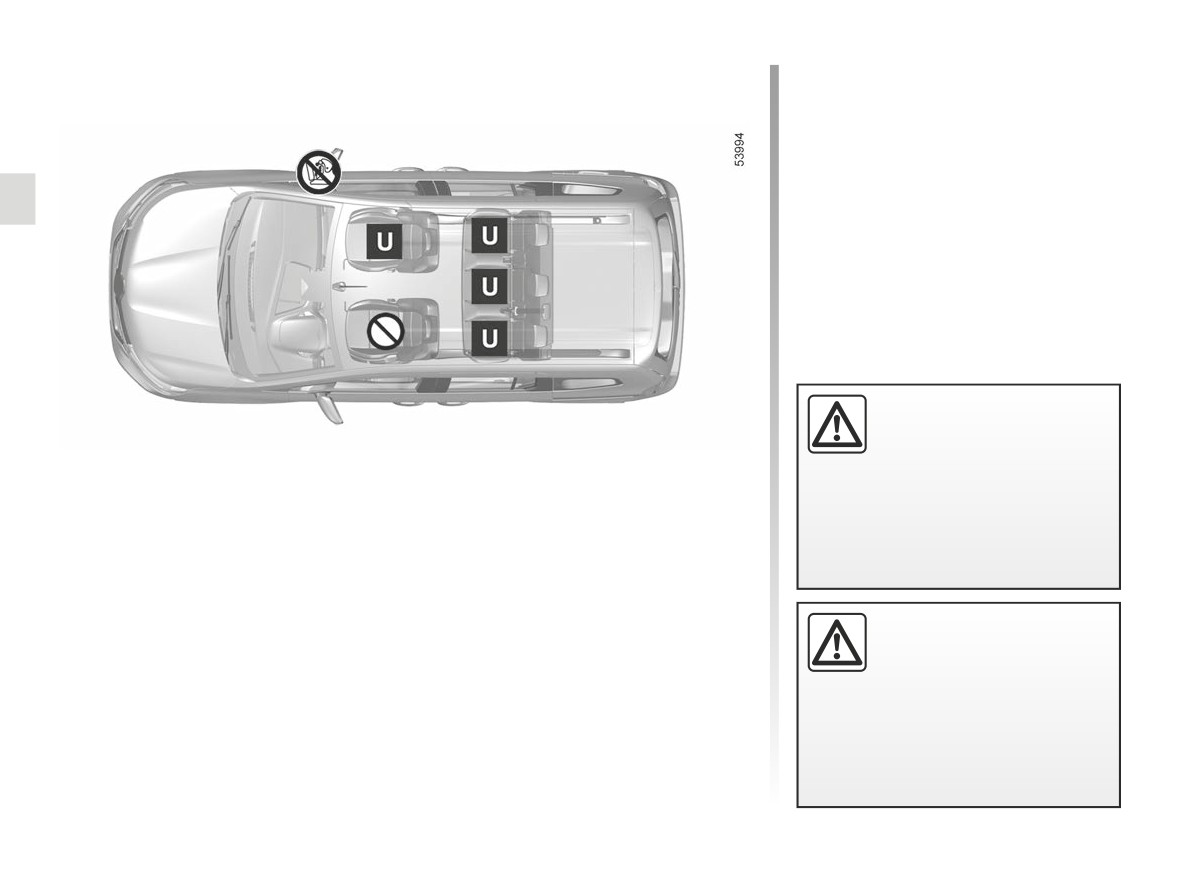
X = Seat not suitable for fitting child seats of this type.
U = Seat allowing a child seat with “Universal” approval to be attached by the seat belt; check that it can be fitted.
(3) Raise the seat to the maximum and position it as far back as possible, tilting the seatback slightly (approximately 15°).
(4) A carrycot can be installed across the vehicle and will take up at least two seats. Position the child with his or her feet nearest
the door.
(5) In order to install a rear-facing child seat, move the front seat as far forward as possible, then move the front seat back as far
as it will go, without allowing it to come into contact with the child seat.
(6) In all situations, remove the rear headrest of the seat on which the child seat is positioned. This must be done before fitting the
child seat. ➥ 3.34. Move the seat in front of the child forwards, move the seatback forward to avoid contact between the seat
and the child’s legs.
(7) RISK OF DEATH OR SERIOUS INJURY: a child seat with a floor support must never be fitted on the rear centre
seat.
(8) RISK OF DEATH OR SERIOUS INJURY: it is forbidden to fit a child seat behind a folded front seat.
1.99
CarManuals2.co
CHILD SEATS: attachment by seat belt (14/14)
Estate version with foldable front passenger seat
Using a child safety system
which is not approved for
this vehicle will not correctly
Child seat attached using the belt
protect the baby or child.
They risk serious or even fatal injury.
¬
Seat which allows a child seat with “Universal” approval to be attached by a
seat belt.
²
Seat not suitable for fitting child seats.
³
Check the status of the airbag before fitting a child seat or allowing a passen-
RISK OF DEATH OR
ger to use the seat.
SERIOUS INJURY: before
fitting a rear-facing child
seat in this seat, make sure
that the front passenger airbag has
been deactivated. ➥ 000.
1.100
CarManuals2.co
CHILD SEATS: fitted using the ISOFIX SYSTEM (1/9)
Van version with front passenger seat equipped with ISOFIX system
Child seat fitted using the ISOFIX
mounting
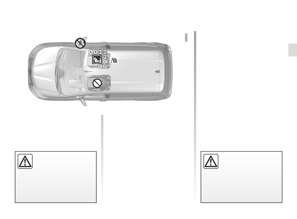
Seat which allows an ISOFIX
child seat to be fitted.
The anchorage point is located on
the back of the front passenger seat.
Seat which does not allow a
²
child seat to be fitted.
³
Check the status of the airbag
before fitting a child seat or allowing a
passenger to use the seat.
Using a child safety system
RISK OF DEATH OR
which is not approved for
SERIOUS INJURY:
this vehicle will not correctly
before fitting a rear facing
protect the baby or child.
child seat on the front pas-
They risk serious or even fatal injury.
senger seat, check that the airbag
has been deactivated ➥ 000.
1.101
CarManuals2.co

CHILD SEATS: fitted using the ISOFIX SYSTEM (2/9)
The table below summarises the information already shown on the diagram on the previous page, to ensure the regula-
tions in force are respected.
Van version with front passenger seat equipped with ISOFIX system
Front passenger seat
Weight of
Size of ISOFIX
Type of child seat
without passenger
the child
seat [Size]
airbag activated on
airbag or with it
passenger side
deactivated
Carrycot fitted across the ve-
F, G
hicle
< 10 kg
X
X
[L1, L2]
Group 0
Rear-facing shell seat
E
< 13 kg
X
IL (1) (2)
Groups 0 or 0 +
[R1]
C
Group 0 +
< 13 kg
X
IL (1) (2)
Shell seat/
[R3]
rear-facing
D
seat
Group 1
9 to 18 kg
X
IL (1) (2)
[R2, R2X]
Forward-facing seat
A, B, B1
9 to 18 kg
IUF - IL (1)
X
Group 1
[F3, F2, F2X]
Booster seat
15 to 25 kg
B2, B3
IUF - IL (1)
X
Groups 2 and 3
22 to 36 kg
Seat i-Size
i-UF (1)
i-U (1) (2)
1.102
CarManuals2.co

CHILD SEATS: fitted using the ISOFIX SYSTEM (3/9)
X = Seat not suitable for fitting child seats of this type.
IUF/IL = On equipped vehicles, seat which allows a child seat with "Universal/Semi-universal or vehicle-specific" approval to be
fitted using the ISOFIX system; check that it can be fitted.
i-U = Suitable for “universal” front-facing and rear-facing i-Size restraint devices.
i-UF = Suitable only for “universal” front-facing and rear-facing i-Size restraint devices.
(1) Raise the seat to the maximum and position it as far back as possible, tilting the seatback slightly (approximately 25°).
The size of the ISOFIX child seat is indicated by a letter:
- A, B, B1 [F3, F2, F2X]: for forward-facing seats in group 1 (9 to 18 kg);
- C, D [R3, R2, R2X]: rear-facing seats or shell seats in group 0+ (less than 13 kg) or group 1 (9 to 18 kg);
- E [R1]: rear-facing shell seats in group 0 (less than 10 kg) or 0+ (less than 13 kg);
- F, G [L1, L2]: carrycots in group 0 (under 10 kg);
- B2, B3: boosters in groups 2 and 3 (15 to 25 kg and 22 to 36 kg).
(2) RISK OF DEATH OR SERIOUS INJURY: before fitting a rear-facing child seat on the front passenger seat, ensure
that the airbag has been deactivated. ➥ 1.110.
1.103
CarManuals2.co

CHILD SEATS: fitted using the ISOFIX SYSTEM (4/9)
The table below summarises the information already shown on the diagram on the following pages, to ensure the appli-
cable regulations are respected.
Estate version with front passenger seat equipped with ISOFIX system
Front passenger seat
Rear seats
Weight of
Size of ISOFIX
airbag
without
Type of child seat
the child
seat [Size]
activated on
passenger
Side seats
Centre seat
passenger
airbag or with
side
it deactivated
Carrycot fitted across the
F, G
vehicle
< 10 kg
X
X
IL (1)
X
[L1, L2]
Group 0
Rear-facing shell seat
E
< 13 kg
X
IL (2) (5)
IL (3)
X
Groups 0 or 0 +
[R1]
C
Group 0 +
< 13 kg
X
IL (2) (5)
IL (3)
X
Shell seat/
[R3]
rear-facing
D
seat
Group 1
9 to 18 kg
X
IL (2) (5)
IL (3)
X
[R2, R2X]
Forward-facing seat
A, B, B1
9 to 18 kg
IUF - IL (2)
X
IUF - IL (3) (4)
X
Group 1
[F3, F2, F2X]
B2
IUF - IL (2)
X
IUF - IL (3) (4)
X
Booster seat
15 to 25 kg
Groups 2 and 3
22 to 36 kg
B3
IUF - IL (2)
X
X
X
Seat i-Size
i-UF (2)
i-U (2) (5)
i-U
X
1.104
CarManuals2.co

CHILD SEATS: fitted using the ISOFIX SYSTEM (5/9)
X = Seat not suitable for fitting child seats of this type.
IUF/IL = On equipped vehicles, seat which allows a child seat with "Universal/Semi-universal or vehicle-specific" approval to be
fitted using the ISOFIX system; check that it can be fitted.
i-U = Suitable for “universal” front-facing and rear-facing i-Size restraint devices.
i-UF = Suitable only for “universal” front-facing and rear-facing i-Size restraint devices.
(1) A carrycot can be installed across the vehicle and will take up at least two seats. Position the child with his or her feet nearest
the door.
(2) Raise the seat to the maximum and position it as far back as possible, tilting the seatback slightly (approximately 25°).
(3) If necessary, position the vehicle seat as far back as possible. In order to install a rear-facing child seat, move the front seat
as far forward as possible, then move the front seat back as far as it will go, without allowing it to come into contact with the
child seat.
(4) In all situations, remove the rear headrest of the seat on which the child seat is positioned. This must be done before fitting the
child seat. ➥ 3.34. Move the seat in front of the child forwards, move the seatback forward to avoid contact between the seat
and the child’s legs.
The size of the ISOFIX child seat is indicated by a letter:
- A, B, B1 [F3, F2, F2X]: for forward-facing seats in group 1 (9 to 18 kg);
- C, D [R3, R2, R2X]: rear-facing seats or shell seats in group 0+ (less than 13 kg) or group 1 (9 to 18 kg);
- E [R1]: rear-facing shell seats in group 0 (less than 10 kg) or 0+ (less than 13 kg);
- F, G [L1, L2]: carrycots in group 0 (under 10 kg);
- B2, B3: boosters in groups 2 and 3 (15 to 25 kg and 22 to 36 kg).
(5) RISK OF DEATH OR SERIOUS INJURY: before fitting a rear-facing child seat on the front passenger seat, ensure
that the airbag has been deactivated. ➥ 1.110.
1.105
CarManuals2.co
CHILD SEATS: fitted using the ISOFIX SYSTEM (6/9)
Estate version with front passenger seat equipped with ISOFIX system
Child seat fitted using the ISOFIX
mounting
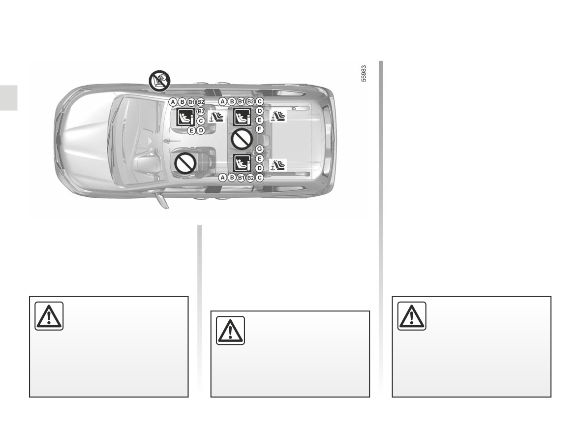
Seat which allows an ISOFIX
child seat to be fitted.
The rear side seats are equipped
with an anchorage point allowing a
forward-facing ISOFIX child seat with
"Universal" approval to be attached.
The anchoring points are located
on the passenger seatback for the front
seat and on the luggage compartment
floor for the rear seats.
Seat which does not allow a
²
child seat to be fitted.
³
Check the status of the airbag
before fitting a child seat or allowing a
passenger to use the seat.
Using a child safety system
Fit the child seat in a rear
which is not approved for
seat wherever possible.
RISK OF DEATH OR
this vehicle will not correctly
SERIOUS INJURY:
To install an ISOFIX seat in
protect the baby or child.
before fitting a rear facing
this seat, detach the central
They risk serious or even fatal injury.
child seat on the front pas-
seat belt by hand before engaging
senger seat, check that the airbag
the bolts.
has been deactivated ➥ 000.
1.106
CarManuals2.co
CHILD SEATS: fitted using the ISOFIX SYSTEM (7/9)
Estate version with front passenger seat not equipped with ISOFIX system
Child seat fitted using the ISOFIX
mounting
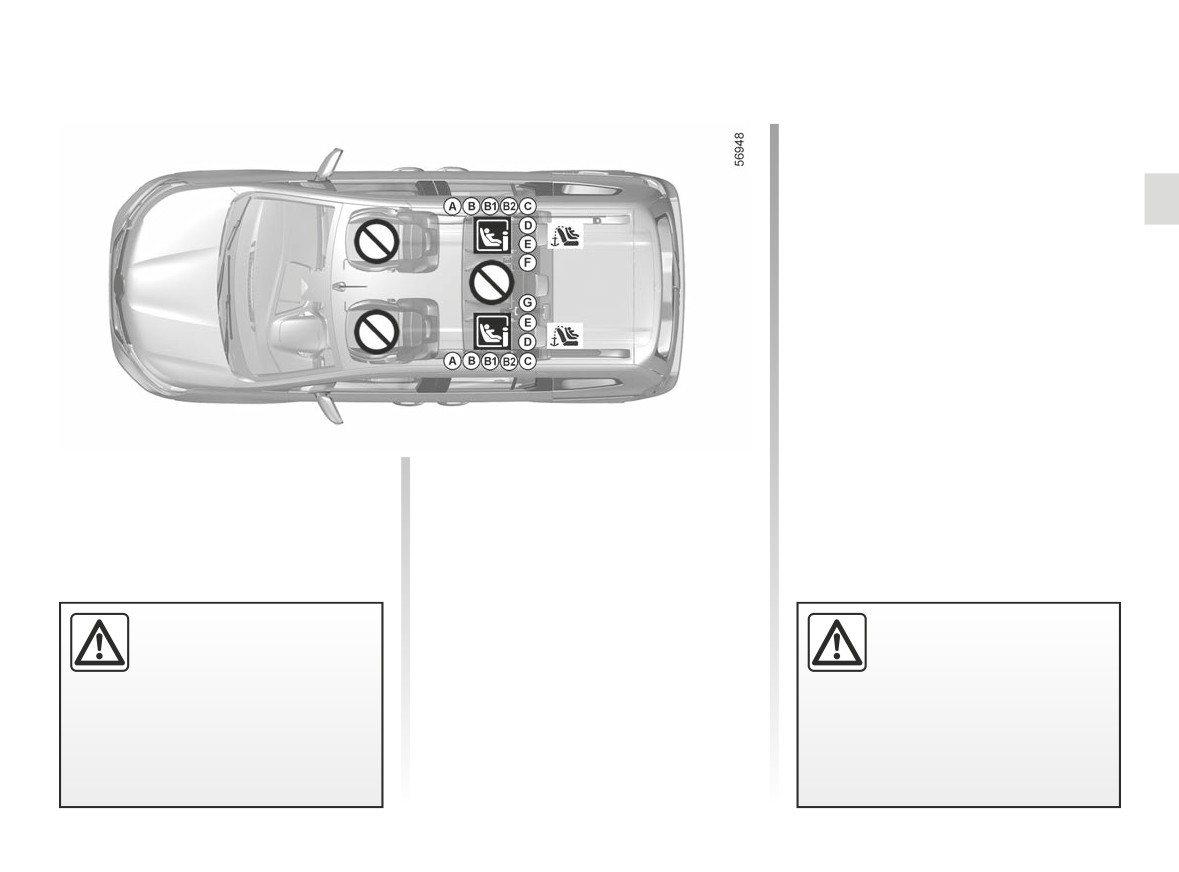
Seat which allows an ISOFIX
child seat to be fitted.
The rear side seats are equipped
with an anchorage point allowing a
forward-facing ISOFIX child seat with
"Universal" approval to be attached.
The anchorage points are located
on the boot floor for the rear seats.
Seat which does not allow a
²
child seat to be fitted.
Using a child safety system
To install a seat ISOFIX,
which is not approved for
detach the central seat belt
this vehicle will not correctly
by hand before engaging
protect the baby or child.
the bolts.
They risk serious or even fatal injury.
1.107
CarManuals2.co

CHILD SEATS: fitted using the ISOFIX SYSTEM (8/9)
The table below summarises the information already shown on the diagram on the previous page, to ensure the regula-
tions in force are respected.
Estate version with front passenger seat not equipped with ISOFIX system
Rear seats
Weight of
Size of ISOFIX
Type of child seat
Front passenger seat
the child
seat [Size]
Side seats (4)
Centre seat
Carrycot fitted across the
F, G
vehicle
< 10 kg
X
IL (1)
X
[L1, L2]
Group 0
Rear-facing shell seat
E
< 13 kg
X
IL (2)
X
Groups 0 or 0 +
[R1]
C
Group 0 +
< 13 kg
X
IL (2)
X
Shell seat/
[R3]
rear-facing
D
seat
Group 1
9 to 18 kg
X
IL (2)
X
[R2, R2X]
Forward-facing seat
A, B, B1
9 to 18 kg
X
IUF - IL (2) (3)
X
Group 1
[F3, F2, F2X]
B2
X
IUF - IL (2) (3)
X
Booster seat
15 to 25 kg
Groups 2 and 3
22 to 36 kg
B3
X
X
X
Seat i-Size
X
i-U
X
1.108
CarManuals2.co

CHILD SEATS: fitted using the ISOFIX SYSTEM (9/9)
X = Seat not suitable for fitting child seats of this type.
IUF/IL = On equipped vehicles, seat which allows a child seat with "Universal/Semi-universal or vehicle-specific" approval to be
fitted using the ISOFIX system; check that it can be fitted.
i-U = Suitable for “universal” front-facing and rear-facing i-Size restraint devices.
i-UF = Suitable only for “universal” front-facing and rear-facing i-Size restraint devices.
(1) A carrycot can be installed across the vehicle and will take up at least two seats. Position the child with his or her feet nearest
the door.
(2) If necessary, position the vehicle seat as far back as possible. In order to install a rear-facing child seat, move the front seat
as far forward as possible, then move the front seat back as far as it will go, without allowing it to come into contact with the
child seat.
(3) In all situations, remove the rear headrest of the seat on which the child seat is positioned. This must be done before fitting the
child seat. ➥ 3.34. Move the seat in front of the child forwards, move the seatback forward to avoid contact between the seat
and the child’s legs.
The size of the ISOFIX child seat is indicated by a letter:
- A, B, B1 [F3, F2, F2X]: for forward-facing seats in group 1 (9 to 18 kg);
- C, D [R3, R2, R2X]: rear-facing seats or shell seats in group 0+ (less than 13 kg) or group 1 (9 to 18 kg);
- E [R1]: rear-facing shell seats in group 0 (less than 10 kg) or 0+ (less than 13 kg);
- F, G [L1, L2]: carrycots in group 0 (under 10 kg);
- B2, B3: boosters in groups 2 and 3 (15 to 25 kg and 22 to 36 kg).
(4) RISK OF DEATH OR SERIOUS INJURY: it is forbidden to fit a child seat behind a folded front seat.
1.109
CarManuals2.co
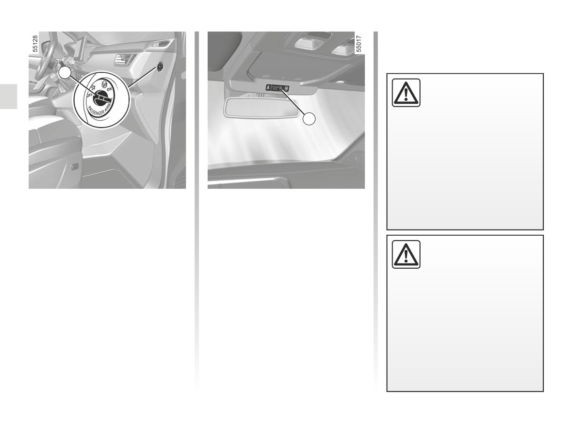
CHILD SAFETY: deactivating, activating AIRBAG front passenger (1/3)
1
The passenger airbag may
only be activated or deacti-
vated when the vehicle is
stationary with the igni-
2
tion off.
If it is interfered with when the ve-
hicle is being driven, indicator lights
å
Switch the ignition off then on again
to reset the airbag in accordance
with the lock position.
Deactivating the front
To deactivate the airbag: with the
vehicle stationary and the ignition
passenger airbag
switched off, push and turn lock 1 to
(depending on the vehicle)
the OFF position.
Before installing a child seat on the
When the ignition is switched on, it is
front passenger seat:
DANGER
essential to check that the warning
- check that the child seat can be in-
Since operation of the front
stalled on this seat;
light
¹
is illuminated on the dis-
passenger airbag is not
play 2.
compatible with the po-
- it is essential to deactivate the
sition of a rear-facing child seat,
airbagfor a rear-facing child seat.
This light remains permanently lit to
NEVER fit a rear-facing child re-
let you know that you can fit a child
straint system in a seat protected
seat.
by an ACTIVATED front AIRBAG.
This can lead to the DEATH of the
CHILD or SERIOUS INJURY.
1.110
CarManuals2.co
CHILD SAFETY: deactivating, activating AIRBAG front passenger (2/3)
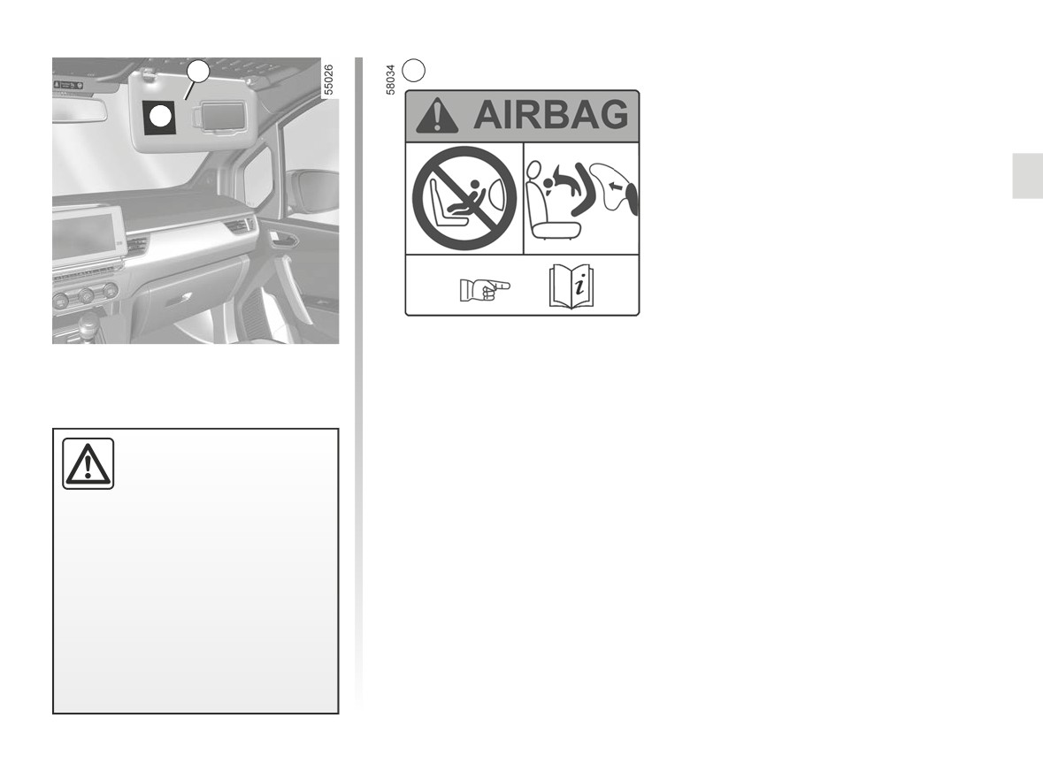
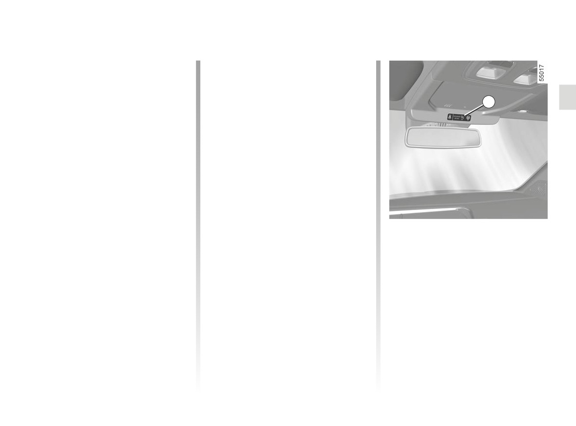
3
A
A
The markings on the dashboard and
labels A on each side of the passen-
ger sun visor 3 (example: label shown
above) remind you of these instruc-
tions.
DANGER
Since operation of the front
passenger airbag is not
compatible with the po-
sition of a rear-facing child seat,
NEVER fit a rear-facing child re-
straint system in a seat protected
by an ACTIVATED front AIRBAG.
This can lead to the DEATH of the
CHILD or SERIOUS INJURY.
1.111
CarManuals2.co
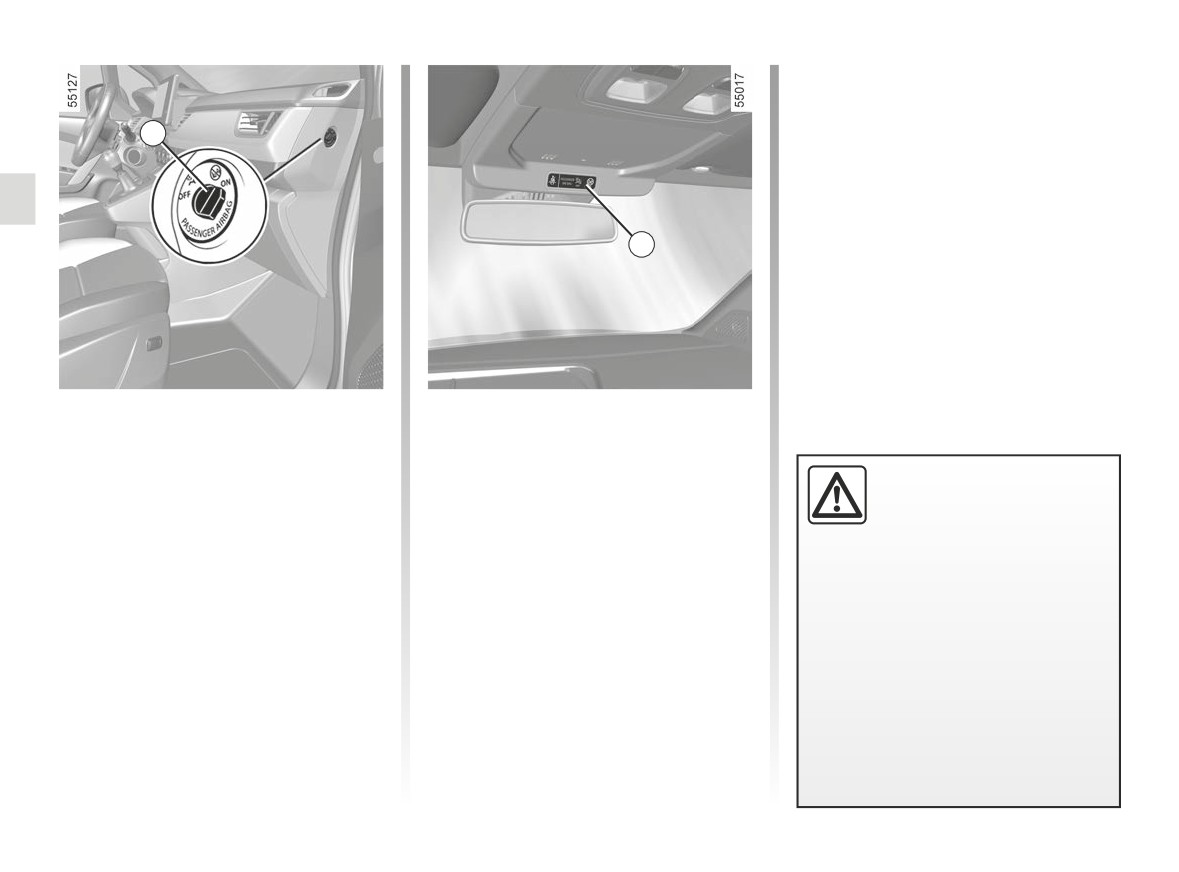
CHILD SAFETY: deactivating, activating AIRBAG front passenger (3/3)
Operating faults
It is forbidden to fit a rear-facing child
seat to the front passenger seat if the
1
airbag activation/deactivation system is
faulty.
Allowing any other passenger to sit in
that seat is not recommended.
2
Contact your approved dealer as soon
as possible.
Activating the front
To restart the airbag: vehicle
stopped, ignition switched off, press
passenger airbag
and turn the lock to1 position ON.
(depending on the vehicle)
When the ignition is switched on, you
The passenger airbag may
You should reactivate the airbag as
only be activated or deacti-
soon as you remove the child seat from
must check that the ¹
warning
vated when the vehicle is
the front passenger seat to ensure the
light is off and that the
warning
stationary with the igni-
protection of the front passenger in the
light comes on the display 2 after each
tion off.
event of an impact.
start-up for around 60 seconds.
If it is interfered with when the ve-
The front passenger airbag is activated.
hicle is being driven, indicator lights
å
Switch the ignition off then on again
to reset the airbag in accordance
with the lock position.
1.112
CarManuals2.co
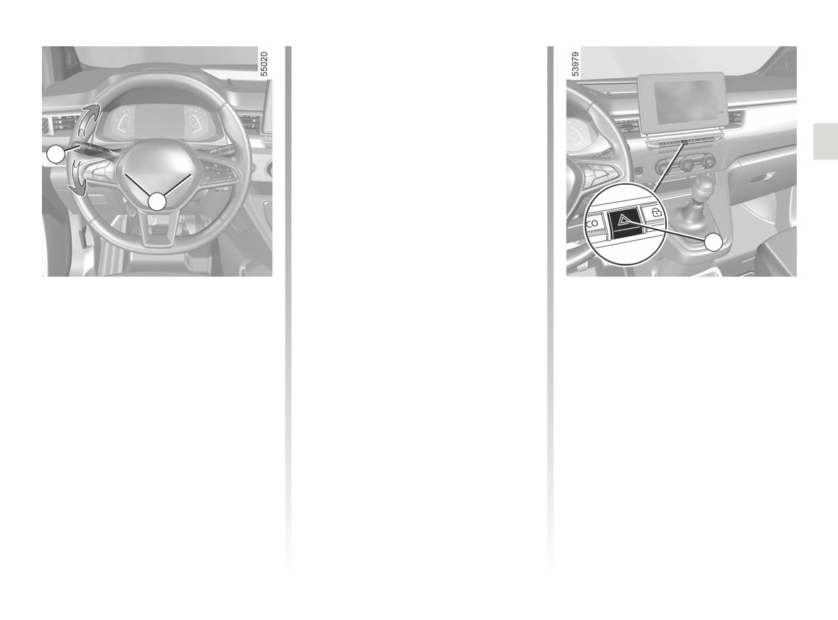
AUDIBLE AND VISUAL SIGNALS
Direction indicators
Move the stalk 1 in the same direc-
tion as you want to move the steering
wheel.
One-touch mode
1
Briefly shift the stalk
1 upwards or
downwards, not exceeding the point
of resistance, then release it: the stalk
will return to its original position and the
A
direction indicator light concerned will
flash three times.
2
Horn
Hazard warning lights
é
Press the steering wheel boss A to ac-
Press switch 2.
tivate the horn.
This switch activates all four direction
indicators and the side indicator lights
simultaneously. It must only be used in
Headlight flasher
an emergency to warn drivers of other
Pull stalk 1 towards you then release it
vehicles that you have had to stop in
to flash the headlights.
an area where stopping is prohibited or
unexpected, or that you are obliged to
drive under special conditions.
1.113
CarManuals2.co
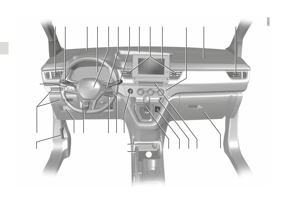
DRIVING POSITION: LEFT-HAND DRIVE (1/2)
1
2
3
4
5
6
7
8
9
10
11
12
1
28
27
25
24
23
22
21
20
26
19
17
16
15
14
13
18
1.114
CarManuals2.co

DRIVING POSITION: LEFT-HAND DRIVE (2/2)
The equipment fitted, described below, DEPENDS ON THE VERSION AND COUNTRY.
1
Side air vent.
14
Controls for:
26
Bonnet release control.
2
Stalk for:
- front seat heating;
27
Switch for:
- direction indicator lights;
- activation/deactivation of ECO
- lighting rheostat for control
- exterior lights;
mode;
instru- ments;
- fog lights.
- activation/deactivation of the
- headlight beam height remote
3
Dashboard storage compartment
driving mode;
adjustment;
sockets USB and accessories
- hazard warning lights;
- activation/deactivation of Lane
socket.
- electric door locking;
Keeping Assist/Lane Departure
4
Instrument panel.
- activation/deactivation of the
Warning;
5
Driver airbag and horn location.
parking distance control;
- activation/deactivation of ESC;
6
Controls for:
- Park Assist.
- activation/deactivation of the
- on-board computer information
15
Storage compartment.
traction control - Extended grip;
read-out and vehicle settings
16
Electronic parking brake.
- activation/deactivation of the
customisation menu,
17
Gearstick.
steering wheel heating;
- remote radio and navigation
18
Smartphone induction charging
- activation/deactivation of the
system.
area.
electric heated windscreen
7
Steering column stalk for wind-
19
Handbrake.
function;
screen and rear screen wash/
20
Accessories socket.
- activation/deactivation of the
wiper.
21
Engine start/stop button.
“Vehicle data confidentiality”
8
Dashboard central storage com-
22
Radio remote control.
mode;
partment.
23
Ignition switch.
- unlocking of the charging flap.
9
Centre air vents.
24
Control for adjusting steering
28
Main switch and controls for cruise
10
Multimedia screen.
wheel height and reach.
control/speed limiter and Stop and
11
Heating or air conditioning con-
25
Storage compartment and fuse
Go adaptive cruise control.
trols.
box.
12
Passenger airbag location.
13
Glovebox.
1.115
CarManuals2.co
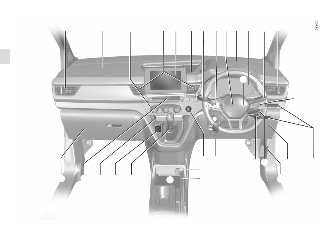
DRIVING POSITION, RIGHT-HAND DRIVE (1/2)
1
2
3
4
5
6
7
8
9
10
11
12
1
2
13
20
19
18
17
15
14
21
28
27
26
25
24
22
16
23
1.116
CarManuals2.co

DRIVER’S POSITION, RIGHT-HAND DRIVE (2/2)
The equipment fitted, described below, DEPENDS ON THE VERSION AND COUNTRY.
1
Side air vent.
13
Main switch and controls for cruise
16
Bonnet release control.
2
Passenger airbag location.
control/speed limiter and Stop and
17
Radio remote control.
3
Heating or air conditioning con-
Go adaptive cruise control.
18
Ignition switch.
trols.
14
Switch for:
19
Control for adjusting steering
4
Centre air vents.
-
lighting rheostat for control
wheel height and reach.
5
Multimedia screen.
instru- ments;
20
Engine start/stop button.
6
Dashboard central storage com-
-
headlight beam height remote
21
Accessories socket.
partment.
adjustment;
22
Handbrake.
7
Steering column stalk for wind-
-
activation/deactivation of Lane
23
Smartphone induction charging
screen and rear screen wash/
Keeping Assist/Lane Departure
area.
wiper.
Warning;
24
Gearstick.
8
Controls for:
-
activation/deactivation of ESC;
25
Electronic parking brake.
- on-board computer information
–
activation/deactivation of the
26
Storage compartment.
read-out and vehicle settings
traction control - Extended grip;
27
Controls for:
customisation menu,
-
activation/deactivation of the
- front seat heating;
- remote radio and navigation
steering wheel heating;
- activation/deactivation of ECO
system.
-
activation/deactivation of the
mode;
9
Driver airbag and horn location.
electric heated windscreen
- activation/deactivation of the
10
Dashboard storage compartment
function;
driving mode;
sockets USB and accessories
-
activation/deactivation of the
- hazard warning lights;
socket.
“Vehicle data confidentiality”
- electric door locking;
11
Instrument panel.
mode;
- activation/deactivation of the
12
Stalk:
-
unlocking of the charging flap.
parking distance control;
- direction indicator lights;
15
Storage compartment and fuse
- Park Assist.
- exterior lights;
flap.
28
Glovebox
– fog lights.
1.117
CarManuals2.co
WARNING LIGHTS (1/4)
The display of information shown below DEPENDS ON THE VEHICLE EQUIPMENT AND COUNTRY.
Side light tell-tale light
Dipped beam headlight tell-
A
B
k
tale light
Main beam headlight tell-tale
á
light
Automatic main beam head-
1
1
light indicator light ➥ 1.153
Front fog light tell-tale
g
Rear fog light tell-tale light
Left-hand direction indicator
c
tell-tale light
Instrument panel A or B: lights up
In some cases, the appearance of a
when the ignition is switched on. Press
warning light is accompanied by a mes-
Right-hand direction indica-
b
tor tell-tale light
or lift the 1 switch as many times as re-
sage on the instrument panel.
quired to adjust the intensity.
If no lights or sounds are ap-
parent, this indicates a fault
For your safety, the warning
in the instrument panel. This
light® requires you to
indicates that it is essential
stop immediately as soon
to stop immediately (as soon as traf-
Warning light
means you
as traffic conditions allow.
fic conditions allow). Ensure that the
should drive very carefully to an
Switch off the engine and do not re-
vehicle is correctly immobilised and
authorised dealer as soon as
start it. Call an approved Dealer.
contact an approved Dealer.
possible. If you fail to follow this
recommendation, you risk damag-
ing your vehicle.
1.118
CarManuals2.co

WARNING LIGHTS (2/4)
The display of information shown below DEPENDS ON THE VEHICLE EQUIPMENT AND COUNTRY.
Indicator lightAirbag
Urgent stop warning light
Warning light
å
®
This comes on when the igni-
This lights up when the ignition
If it appears in red during driv-
tion is switched on and goes out after a
is switched on and goes out as soon as
ing and is accompanied by the
®
few seconds.
the engine is started. It comes on with
indicator light, you must, for your safety,
other warning lights and/or messages,
stop as soon as traffic conditions allow.
If it does not light up when the ignition
and is accompanied by a beep.
Switch off the engine and do not restart
is switched on, or if it lights up when the
it.
engine is running, it indicates a fault in
It requires you to stop immediately, for
the system.
your own safety, as soon as traffic con-
Call an approved Dealer.
ditions allow. Switch off the engine and
Contact your approved Dealer as soon
If it appears in yellow during driving and
do not restart it.
as possible.
is accompanied by the
warn-
Contact an approved Dealer.
ing light, visit an approved dealer as
Handbrake
“on” or elec-
tronic parking brake warn-
Warning light
soon as possible. Meanwhile, drive
with care. If you fail to follow this rec-
ing light ➥ 2.11 ➥ 2.12
This lights up when the ignition
ommendation, you risk damaging your
Front seat belt reminder
is switched on and goes out as soon as
vehicle.
ß
warning light
the engine is started. It can light up in
conjunction with other warning lights
Cruise control and
It lights up on the central display when
Ð Ï
and/or messages on the instrument
speed limiter indica-
the engine is started then, if the driver's
panel.
tor lights ➥ 2.84 ➥ 2.88
seat belt is not fastened when the vehi-
cle reaches a speed of approximately
It means you should drive very care-
Adaptive cruise control
warning light Stop and Go
12 mph (20 km/h), the light flashes and
fully to an approved dealer as soon as
a beep sounds for about 120 seconds
possible. If you fail to follow this recom-
➥ 2.93
➥ 1.64.
mendation, you risk damaging your ve-
hicle.
Door status warning light
➥ 1.44
1.119
CarManuals2.co

WARNING LIGHTS (3/4)
The display of information shown below DEPENDS ON THE VEHICLE EQUIPMENT AND COUNTRY.
Electrotechnical system
Traction battery gauge indi-
Secondary
12 V battery
warning light
cator light
Ú
charge warning light
It appears when the temperature of the
This lights up in yellow when the trac-
If it comes on, accompanied by the
electrical assembly is too high. Stop the
tion battery charge level has reached
®
warning light and a beep,
vehicle without switching off the igni-
the reserve threshold ➥ 1.122.
this means that the electrical cir-
tion. The temperature should lower and
cuit is overcharged or discharged
Traction battery fault warn-
the warning light should disappear. If
➥ 1.9.
ing light
this is not the case, please consult an
ECO function indicator light
Authorised Dealer.
If it appears, accompanied by the
warning light, this indicates a
This lights up when ECO
The warning light may be accompa-
fault related to the operation of the trac-
mode is activated ➥ 2.16 ➥ 2.22.
nied by a reduction in vehicle perfor-
tion battery. Contact your approved
mance.
Charging cord plugged in
Dealer straight away.
warning light
Electrotechnical system
Limited performance warn-
fault warning light
This comes on when the charging lead
ing light
is plugged into the vehicle ➥ 1.9.
If it comes on, this indicates an electro-
This appears when the traction battery
technical fault related to the electrical
Overspeed warning light
temporarily does not deliver its nominal
assembly (traction battery and electric
➥ 000
power. During this period, vehicle per-
motor). Contact your approved Dealer
formance is reduced.
(Depending on the vehi-
straight away.
cle) Advanced Safety
Opt for a smoother driving style until the
Electric motor fault warning
warning light, fault light or not avail-
warning light disappears.
light
able ➥ 2.61
When it comes on, this indicates a fault
Charging programme indi-
with the electrotechnical system linked
cator lights ➥ 1.21
to the electric motor. Contact your ap-
Warning lights for air condi-
proved Dealer straight away.
tioning programming ➥ 3.13
1.120
CarManuals2.co
WARNING LIGHTS (4/4)
The display of information shown below DEPENDS ON THE VEHICLE EQUIPMENT AND COUNTRY.
Anti-lock braking warning
Variable power assisted
x
light
U
steering warning light
This lights up when the ignition is
It lights up when the ignition or the
switched on and goes out after a few
engine is switched on and goes off after
C
seconds.
a few seconds.
If it does not go out after the ignition is
If it comes on while driving, alongside
switched on, or lights up when driving,
the warning light
®
, this means
there is a fault with the ABS. Braking
there is a system fault.
will then be as normal, without the ABS.
Contact an authorised dealer.
Contact an approved Dealer as soon as
Lane departure system
possible.
warning light ➥ 2.36
Warning light for the elec-
Lane Keeping Assist system
tronic stability program
warning light ➥ 2.41
(ESC) and traction control system
There are several reasons for the warn-
ing light to appear: ➥ 2.30.
ection warning light ➥ 2.41
On display C
Warning light for non-availa-
Brake circuit fault warning
Passenger Airbag ON
D
➥ 1.110
bility of the electronic stabil-
light
ity program (ESC) and traction con-
If it comes on during braking and is ac-
Passenger Airbag OFF
trol system
¹
➥ 1.110
companied by the
®
warning light
Tyre pressure monitoring
and a beep, it indicates that the fluid
Seat belt reminder warning
system ➥ 2.25.
level in the circuit is low or that there is
ß
lights ➥ 1.62.
a braking system fault. Stop as soon as
traffic conditions allow and consult an
warning light ➥ 2.107
approved dealer.
1.121
CarManuals2.co
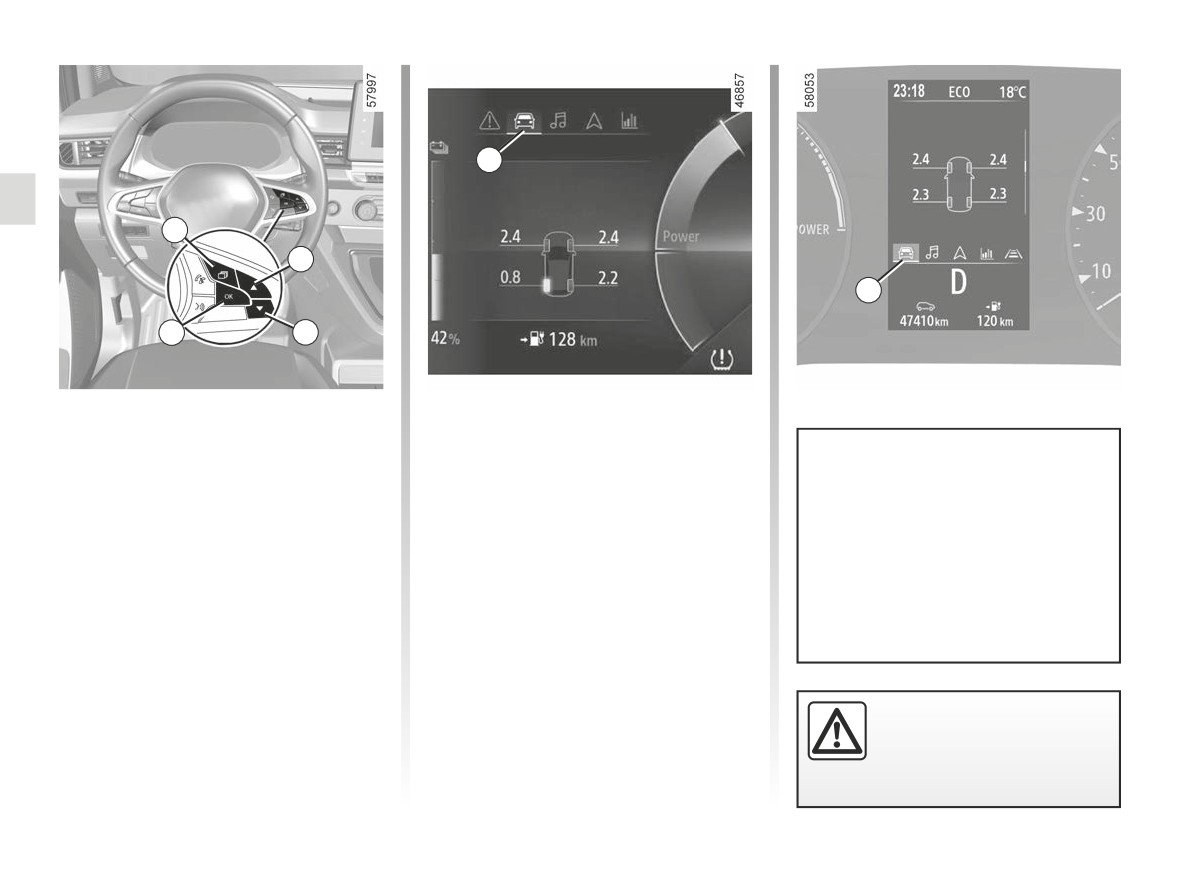
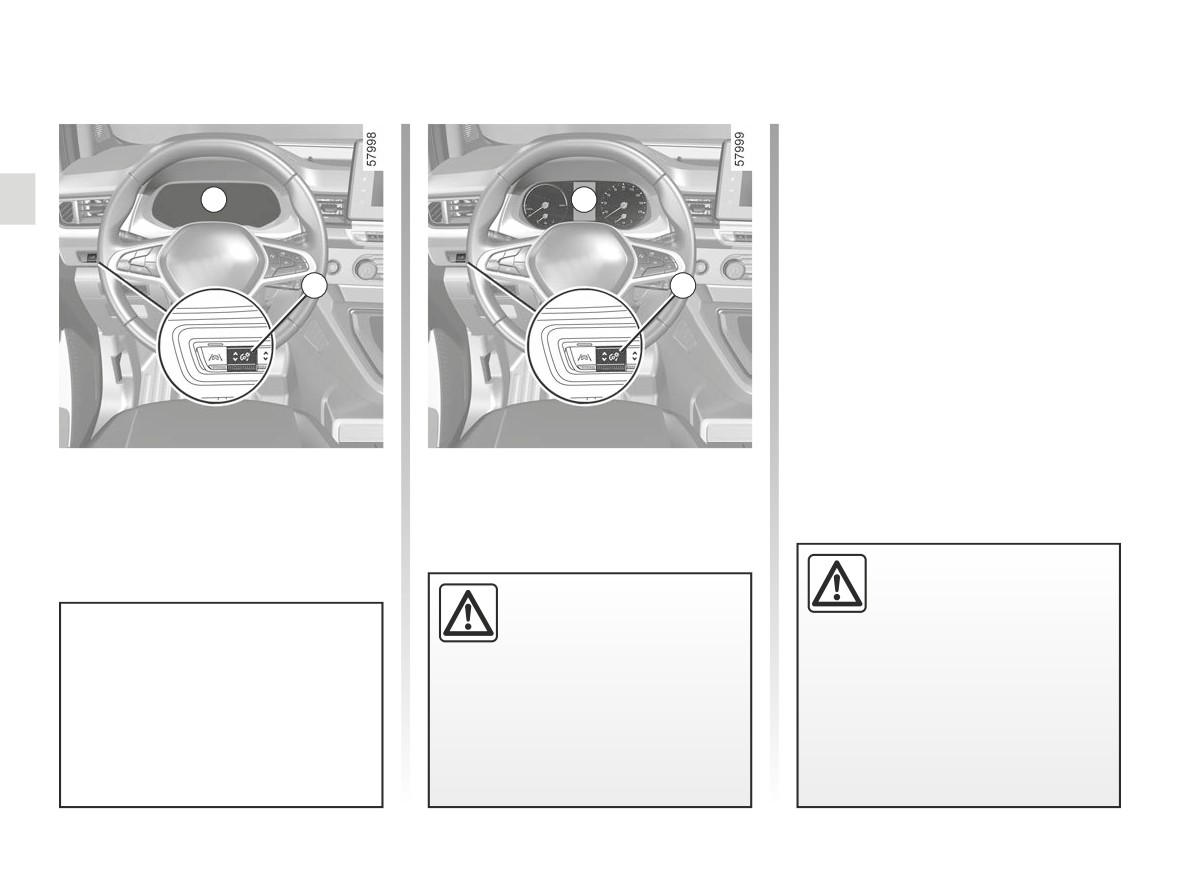
DISPLAYS AND INDICATORS (1/6)
5
1
2
5
4
3
Instrument panel in miles
Vehicles fitted with a multimedia
(option to switch to km/h)
screen.
Vehicles not fitted with a multimedia
With the vehicle stationary and the
screen
engine on, from the multimedia
To use certain driving aid functions,
screen, select the “Settings” menu, the
- With the ignition off, press the
1
it is necessary to change the unit
“System” tab, then “Units”.
switch as many times as required to
of measurement on the instrument
reach the vehicle tab 5;
Note: in both cases, once the battery
panel in order to obtain the correct
- press 2 or 3 repeatedly to access
is switched off, the on-board computer
information when driving in a coun-
“Settings”, then press 4 “OK ";
automatically returns to the original unit
try where the speed units differ from
- repeat the same operation to access
of measurement.
those set as default on your vehicle.
"DASHBOARD", then "Units".
To return to the previous mode, repeat
the same operation.
Please refer to the multimedia instruc-
tions for more information.
For safety reasons, change
these settings while the ve-
hicle is stationary.
1.122
CarManuals2.co
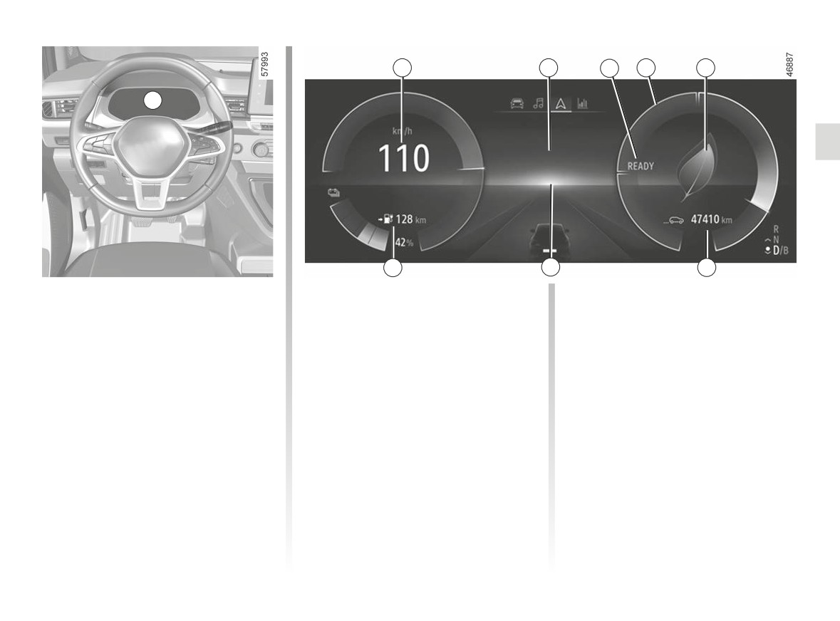
DISPLAYS AND INDICATORS (2/6)
6
7
8
9
10
A
13
12
11
Instrument panel A
Overspeed buzzer
Message indicating vehicle ready
for driving 8
lights up when the driver’s door is
Depending on the vehicle and country,
opened. In some cases, the appear-
The “READY" message appears when
the
warning light is displayed
ance of a warning light is accompanied
the engine starts and disappears when
and a beep sounds. This beep sounds
by a message.
the vehicle speed exceeds
3 mph
as soon as the vehicle is travelling at
Depending on the vehicle, you can cus-
(5 km/h).
over 75 mph (120 km/h).
tomise your instrument panel with the
This warning light remains lit for as long
Charge meter 9 ➥ 2.16
content and colours of your choice.
as the vehicle is travelling at over
For vehicles fitted with a multimedia
74 mph (120 km/h).
Driving style indicator 10 ➥ 2.16
screen, refer to the equipment instruc-
tions.
Multimedia information 7
Total mileage recorder 11 ➥ 1.131
For vehicles not fitted with a multimedia
screen ➥ 1.138.
Depending on the vehicle, you can dis-
Trip computer 12 ➥ 1.128
play information from the multimedia
Speedometer 6
screen (the compass, telephone, navi-
Estimated range 13.
gation etc.).
Please refer to the multimedia instruc-
tions for further information.
1.123
CarManuals2.co
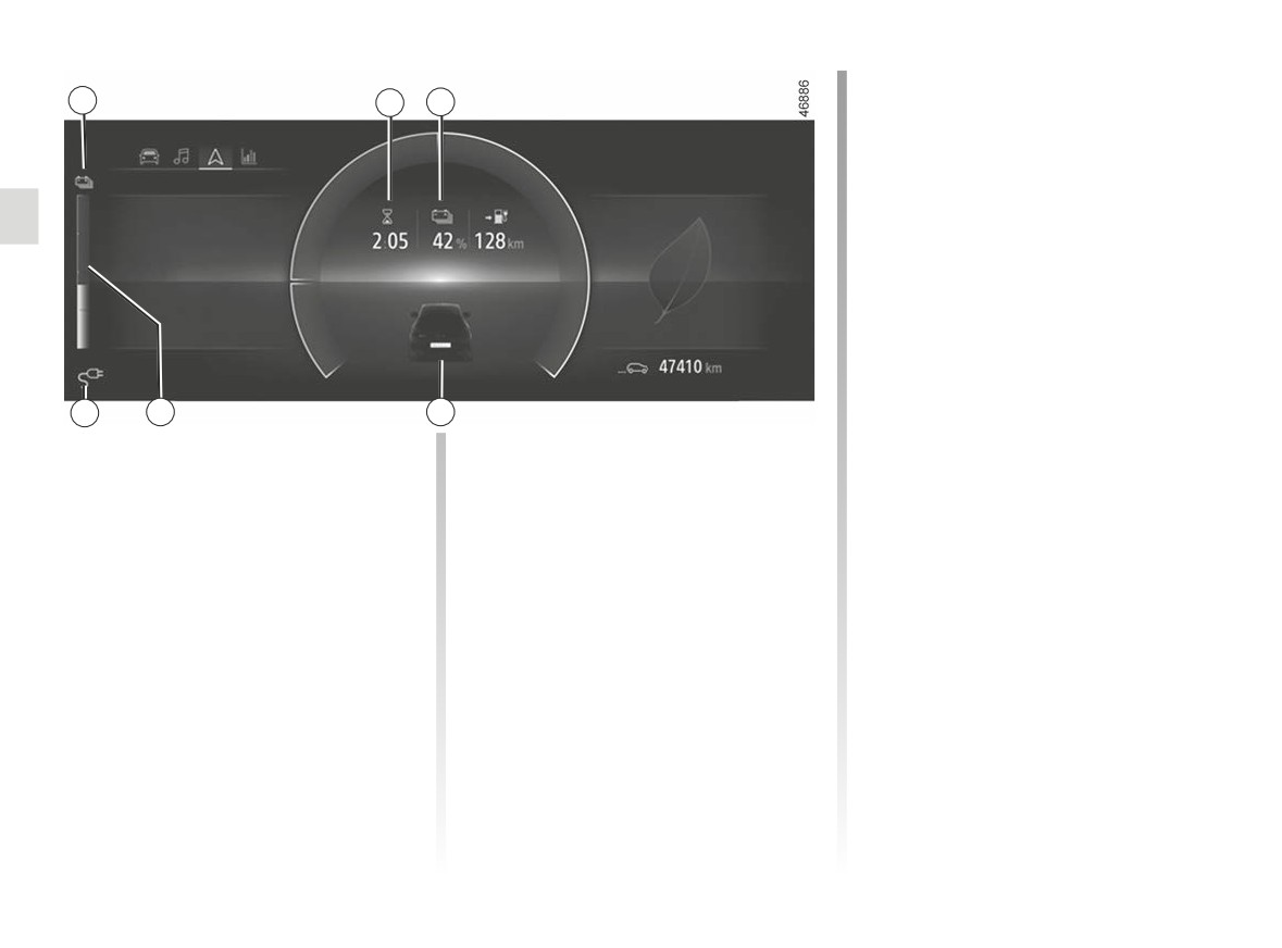
DISPLAYS AND INDICATORS (3/6)
Reserve threshold
14
15
16
When the traction battery charge level
reaches approximately 12%, the gauge
appear in
and indicator light 14
yellow, accompanied by a beep.
To optimise your range ➥ 2.22.
Immobilisation threshold imminent
When the charge level reaches approx-
imately 6%, a beep sounds again and
the gauge illuminates in red.
When the charge level reaches 5%, the
range value is no longer displayed.
19
18
17
Remaining charge time 15
Charge level 18
The gauge indicates the level of energy
Traction battery charge rate 16
remaining.
Opening element warning light 17
Charging cable “Plugged In”
Shows when a door, the tailgate or
warning light 19
charging flap is open or not closed
(depending on the vehicle)
properly.
This comes on when the charging cord
is plugged into the vehicle.
1.124
CarManuals2.co
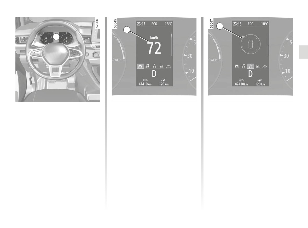
DISPLAYS AND INDICATORS (4/6)
21
20
B
Instrument panel B
Speedometer 20
Multimedia information 21
lights up when the driver’s door is
Depending on the vehicle, you can dis-
Overspeed buzzer
opened. In some cases, the appear-
play information from the multimedia
ance of a warning light is accompanied
Depending on the vehicle and country,
screen (the compass, telephone, navi-
by a message.
gation etc.).
the
warning light is displayed
Depending on the vehicle, you can cus-
Please refer to the multimedia instruc-
and a beep sounds. This beep sounds
tomise your instrument panel with the
tions for further information.
as soon as the vehicle is travelling at
content and colours of your choice.
over 75 mph (120 km/h).
For vehicles fitted with a multimedia
This warning light remains lit for as long
screen, refer to the equipment instruc-
as the vehicle is travelling at over
tions.
74 mph (120 km/h).
For vehicles not fitted with a multimedia
screen ➥ 1.138.
1.125
CarManuals2.co
DISPLAYS AND INDICATORS (5/6)
22
25
26
24
23
28
27
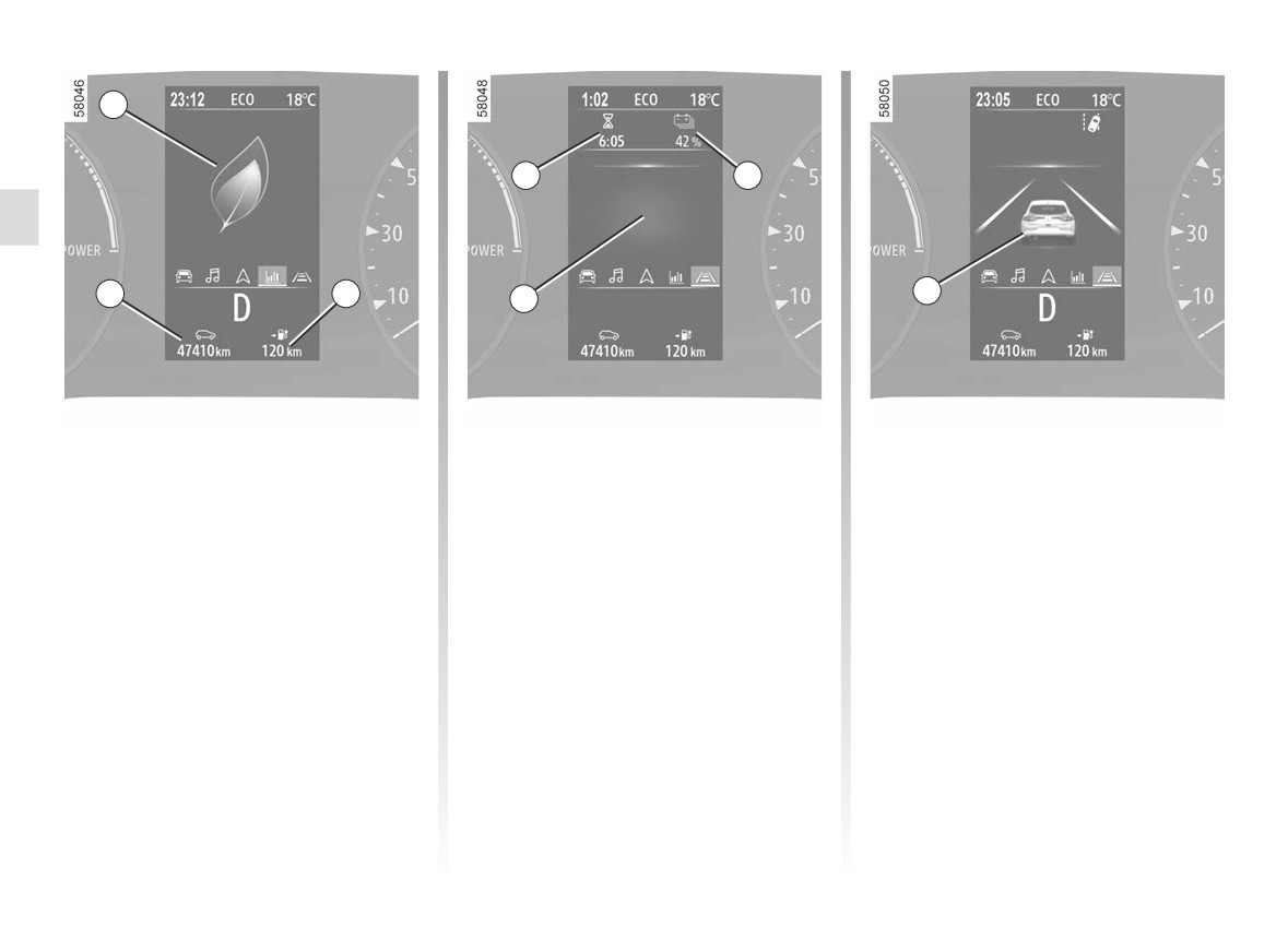
Driving style indicator 22 ➥ 2.16
Remaining charge time 25
Opening element warning light 28
Shows when a door, the tailgate or
Estimated range 23.
Traction battery charge rate 26
charging flap is open or not closed
Total mileage recorder 24 ➥ 1.131
Trip computer 27 ➥ 1.128
properly.
1.126
CarManuals2.co
DISPLAYS AND INDICATORS (6/6)
30
29
29
31
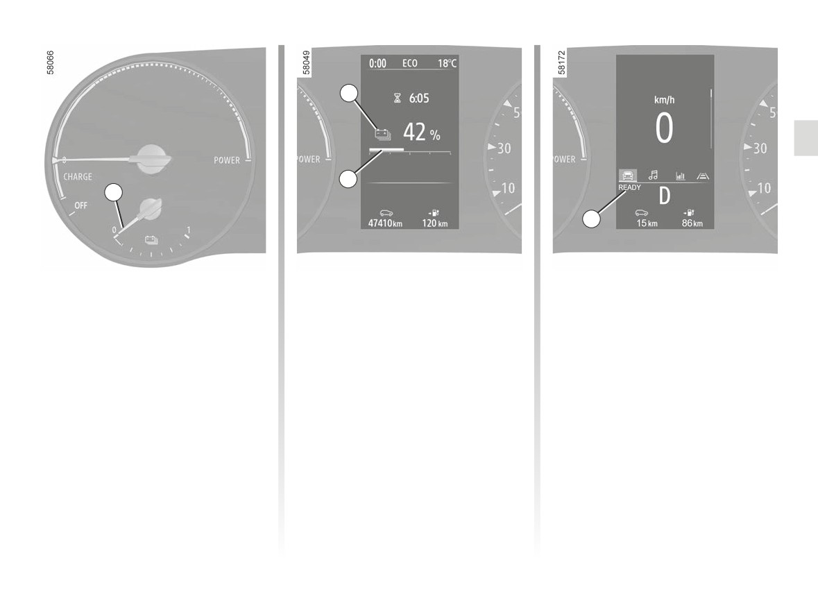
Charge level 29
Immobilisation threshold imminent
Message indicating vehicle ready
for driving 31
The gauge indicates the level of energy
When the charge level reaches approx-
remaining.
imately 6%, a beep sounds again and
The “READY" message appears when
the gauge illuminates in red.
the engine starts and disappears when
Reserve threshold
When the charge level reaches 5%, the
the vehicle speed exceeds
3 mph
When the traction battery charge level
range value is no longer displayed.
(5 km/h).
reaches approximately 12%, the gauge
and indicator light 30
appear in
yellow, accompanied by a beep.
To optimise your range ➥ 2.22.
1.127
CarManuals2.co
TRIP COMPUTER: general information (1/3)
A
A
5
1
2
4
3
8
7
6
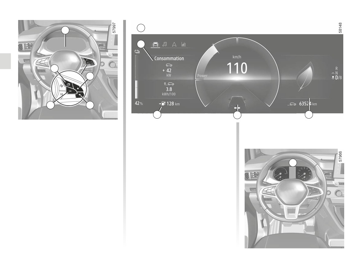
Trip computer and warning
Vehicle fitted with trip computer A
system A or B
The functions are distributed in
zones 5, 6, 7, and 8. The location of the
Depending on the vehicle, this includes
zones differs depending on the style
the following functions:
selected.
- distance travelled;
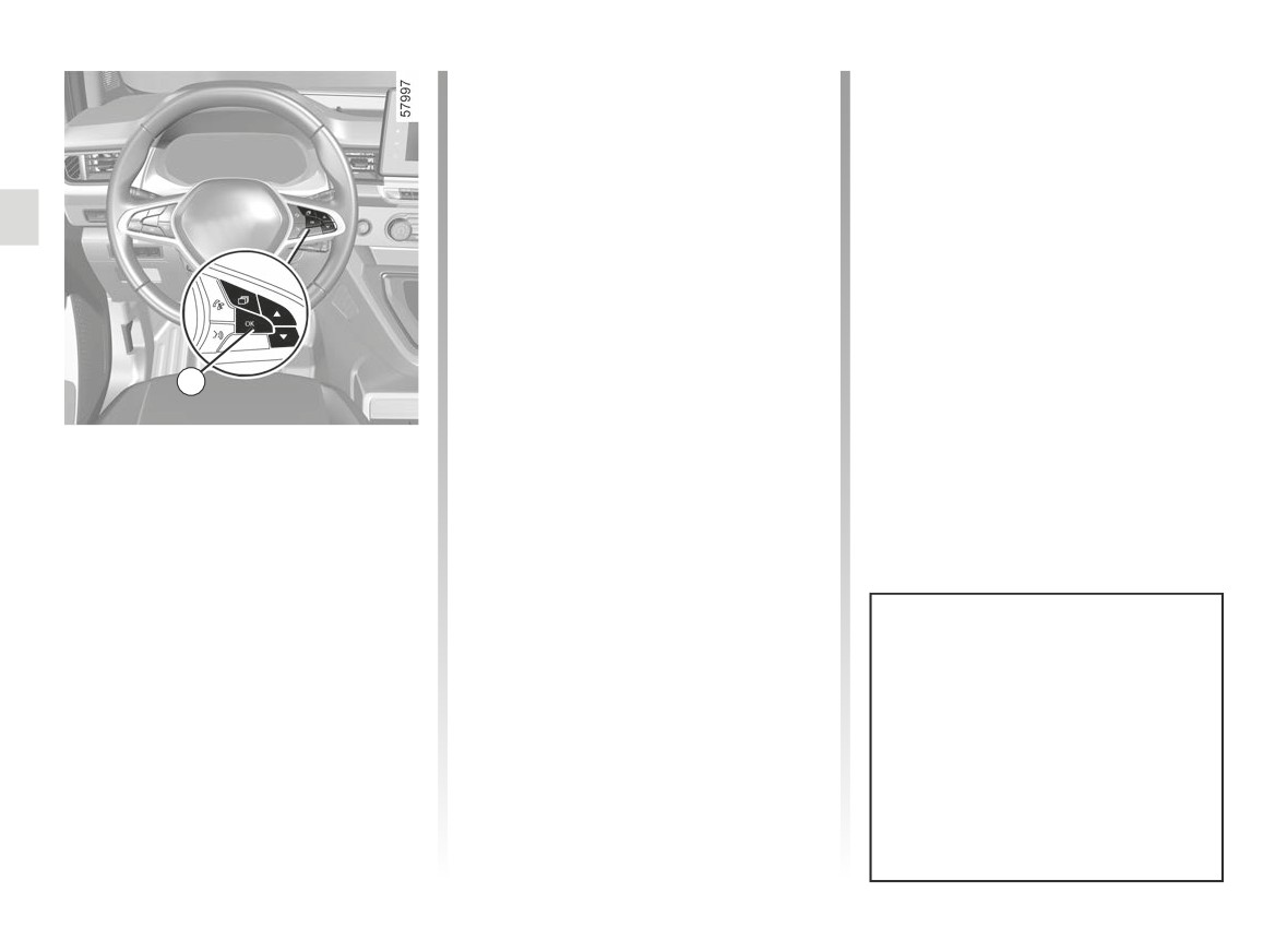
Press the 1 switch to browse between
B
- journey settings;
menus and select functions by repeat-
- information messages;
edly pressing switch 2 or 3, then if nec-
- operating fault messages
(con-
essary use the 4 switch to confirm “OK”.
- warning messages (connected to the
®
warning light);
– vehicle settings customisation menu
➥ 1.138.
All these functions are described on the
following pages.
1.128
CarManuals2.co
TRIP COMPUTER: general information (2/3)
Selections
(the display depends on the vehicle
B
equipment and country)
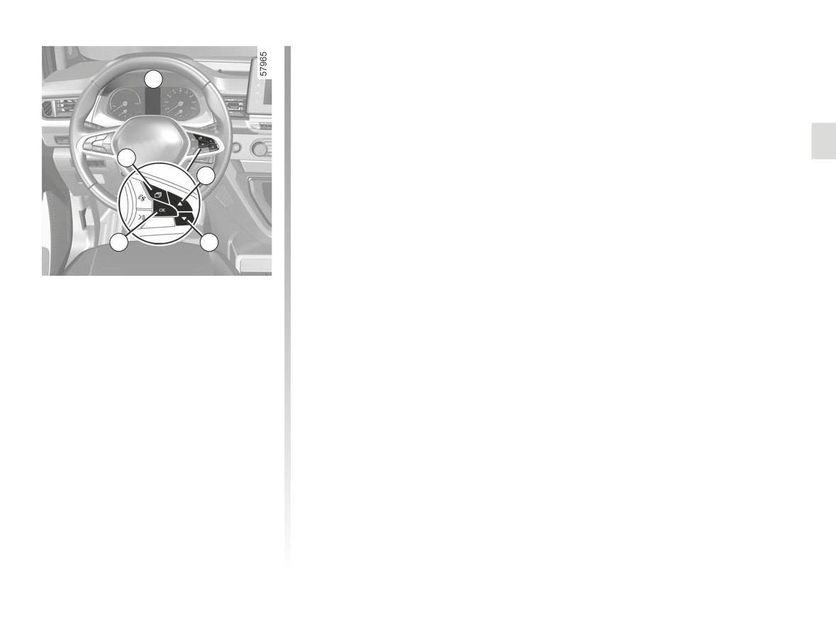
From the vehicle tab:
a) journey settings:
- average energy consumption
1
since the last reset and current
2
energy consumption;
- distance travelled since the last
reset and average speed.
b) reset the tyre pressure;
4
3
c) time (depending on the vehicle);
d) service interval;
Vehicle fitted with trip computer B
e) only when stationary, vehicle set-
Press the 1 switch as many times as re-
tings customisation menu ➥ 1.138.
quired to reach the “Vehicle” tab.
From the message tab:
Press repeatedly using the 2 or 3 con-
trol, then if necessary use the 4 switch
f) trip log, operating faults and informa-
to confirm “OK”.
tion message readout.
1.129
CarManuals2.co
TRIP COMPUTER: general information (3/3)
Reading energy consumption
Manual reset
Select one of the trip settings, press and
values
hold switch 4 OK to reset the range.
Some vehicle equipment items con-
sume energy: the energy consumed
Automatic reset
by the vehicle may therefore differ from
The range is automatically reset at the
the energy consumed on the electric
end of a full recharge of the traction
counter.
battery to a value calculated based on
the energy consumption since the last
reset.
Interpreting some of the
values displayed after
resetting
4
Average energy consumption and
speed are all the more stable and
meaningful the greater the distance
Resetting the journey
travelled since the last reset.
parameters (reset button)
With one of the trip parameters se-
Resetting the estimated
lected as the display, press and hold
range
the
4 switch “OK” until the display
After a full recharge of the traction bat-
resets to zero.
tery, you can select two types of reset-
ting: manual or automatic.
Automatic resetting of the
journey parameters
Some on-board
computer infor-
Resetting occurs automatically when
mation appears on the navigation
the maximum value of any of the pa-
system display.
rameters is exceeded.
The trip settings mileage recorder
is reset simultaneously in the on-
board computer and the navigation
system.
1.130
CarManuals2.co
TRIP COMPUTER AND WARNING SYSTEM: journey parameters (1/4)
The display of information shown below DEPENDS ON THE VEHICLE EQUIPMENT AND COUNTRY.
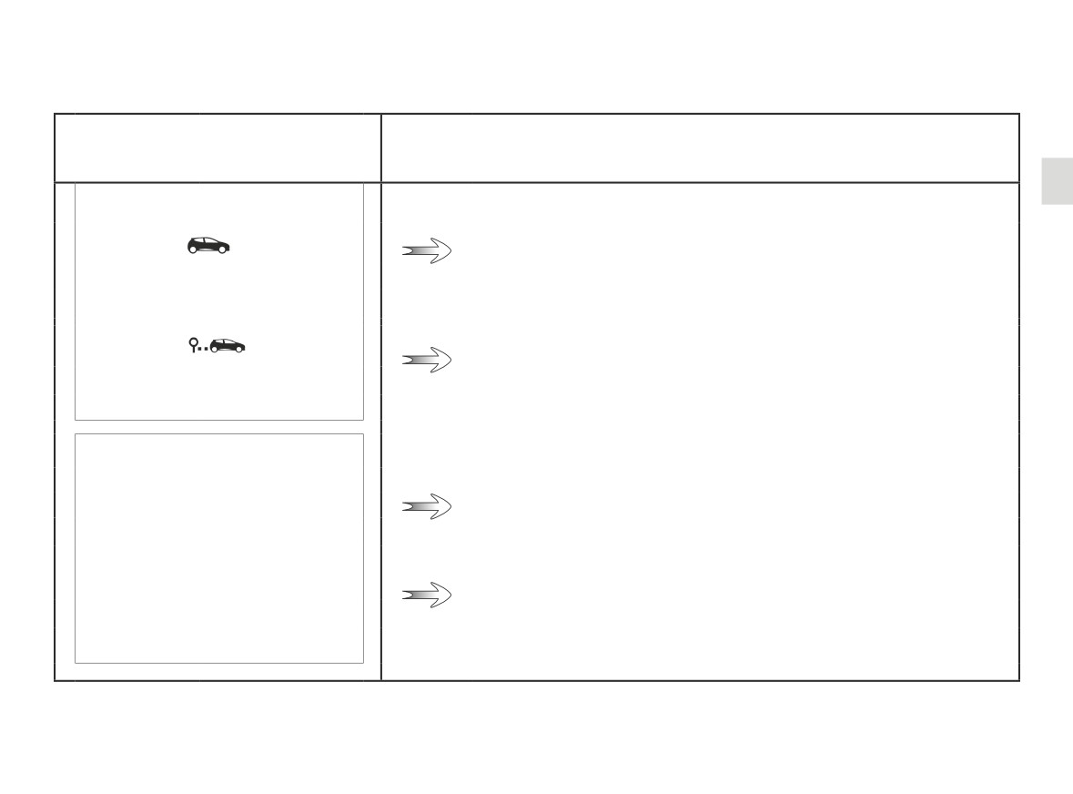
Examples of selections
Interpreting the display selected
Consumption
a) Trip settings.
Current energy consumption.
+ 13,4
kW
Average energy consumption.
The value is displayed after having travelled at least 400 metres since
12,8
the last reset.
kWh/100
Journey
Average speed since the last reset.
42,2
The value is displayed after driving 400 metres.
km/h
1284,7
Distance travelled since the last reset.
km
1.131
CarManuals2.co
TRIP COMPUTER AND WARNING SYSTEM: journey parameters (2/4)
The display of information shown below DEPENDS ON THE VEHICLE EQUIPMENT AND COUNTRY.
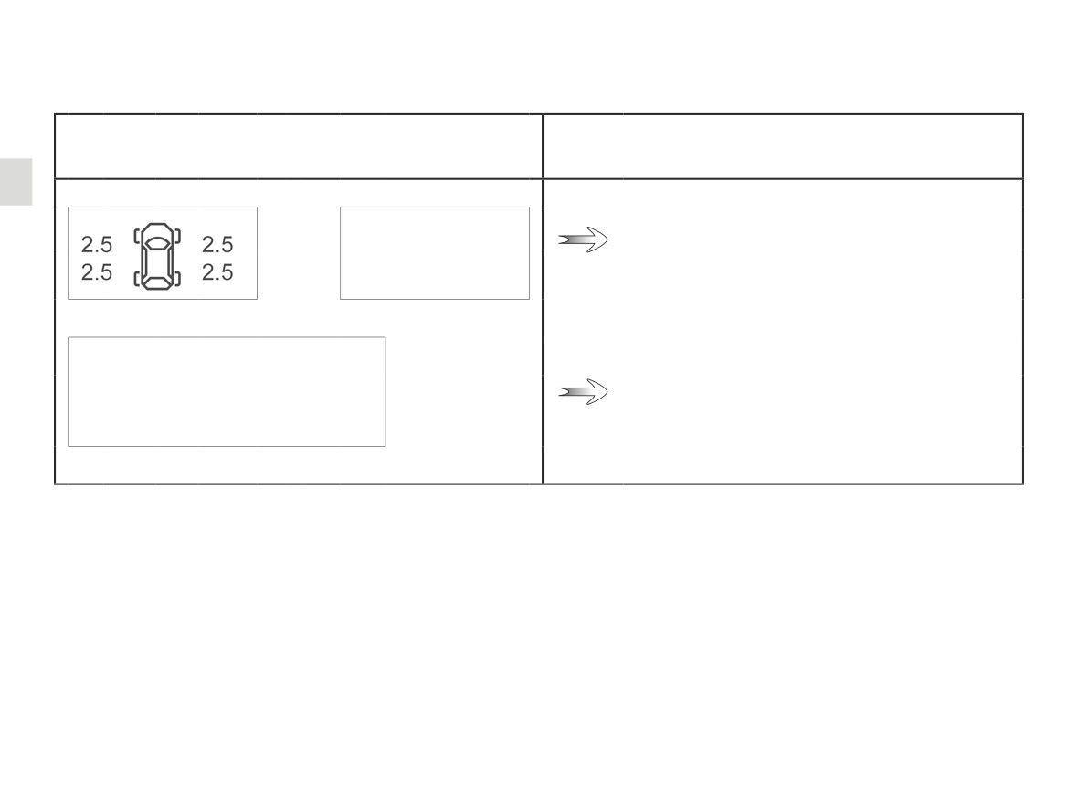
Examples of selections
Interpreting the display selected
b) Tyre pressure reset ➥ 2.25
+
Tyre pressure
12:00
c) Clock
1.132
CarManuals2.co

TRIP COMPUTER AND WARNING SYSTEM: journey parameters (3/4)
The display of information shown below DEPENDS ON THE VEHICLE EQUIPMENT AND COUNTRY.
Examples of selections
Interpreting the display selected
d) Service interval.
Service in
Distance remaining until the next service (displayed in miles/kilo-
metres), then when the service nears, several scenarios are possible:
1,210 miles
- range less than 930 miles (1,500 km) or one month: the message
or 3 months
“Service Due in” is displayed accompanied by the distance or the
time;
- when a service is due, the message “Service Due in” is displayed
accompanied by the nearest term (distance or time);
- range equal to 0 miles (0 km) or date of service reached: the
message “Service Required” is displayed accompanied by the
The vehicle requires a service as soon as possible.
Resetting the display after the service in accordance with the maintenance schedule.
The service interval must only be reset after a service which complies with the recommendations in the maintenance schedule.
Special note: To reset the service interval, press and hold one of the display reset buttons for approximately 10 seconds until
the display shows the mileage permanently.
1.133
CarManuals2.co
TRIP COMPUTER AND WARNING SYSTEM: journey parameters (4/4)
The display of information shown below DEPENDS ON THE VEHICLE EQUIPMENT AND COUNTRY.
Examples of selections
Interpreting the display selected
Settings
e) Vehicle settings personalisation menu ➥ 1.138.
(OK)
Tailgate open
f) Trip log.
Successive display:
- information messages;
- operating fault messages.
1.134
CarManuals2.co

TRIP COMPUTER AND WARNING SYSTEM: information messages
These can help in the vehicle starting phase, or give information about a selection or a driving status.
Examples of information messages are given in the following pages.
Examples of messages
Interpreting the display selected
“Disconnect cable to start”
Indicates that the charging cord is still plugged into the vehicle.
“Parking Brake ON”
Indicates that the parking brake has been applied.
Unplug, then plug in the vehicle.
“Check connections”
If the message still shows, this may be caused by the external charging conditions
or by the home installation.
Indicates an electrical fault while charging. Restart charging.
“Power cut while charging”
If this does not work, have the electrical installation checked.
1.135
CarManuals2.co

TRIP COMPUTER AND WARNING SYSTEM: operating fault messages
These appear with the
warning light and mean that you should drive very carefully to an authorised dealer as
soon as possible. If you fail to follow this recommendation, you risk damaging your vehicle.
warning light stays on. Examples of operating fault messages are given in the following pages.
Examples of messages
Interpreting the display selected
«WARNING: Check Airbag»
Indicates a fault in the restraint system in addition to the seat belts. In the event of an
accident, it is possible that they may not be triggered.
«Check vehicle»
Indicates a fault on one of the pedal sensors or in the 12 V battery management
system.
«WARNING: Check Braking System»
Indicates wear or the need to check the braking system.
«Check Vehicle plug»
Indicates overheating at the vehicle-side charging socket. Wait for about 20 minutes
and try again. If this does not work, contact an authorised dealer.
«Check Electric System»
Indicates a fault in the traction system.
“WARNING: Check SOS Call”
Indicates a fault in the emergency call system.
«Battery charging impossible»
Indicates a fault on the traction battery recharge system.
1.136
CarManuals2.co

TRIP COMPUTER AND WARNING SYSTEM: warning message
These appear with the® warning light and require you to stop immediately, for your own safety, as soon as traffic
conditions allow. Stop your engine and do not restart it. Call an approved Dealer.
Examples of warning messages are given in the following pages. Note: the messages appear on the display either individually
or alternately (when there are several messages to be displayed), and may be accompanied by a warning light and/or a beep.
Examples of messages
Interpreting the display selected
«WARNING: Braking System»
Indicates a fault in the braking system.
«WARNING: Power Steering»
Indicates a fault in the steering.
«Electric motor failure»
Indicates that the vehicle is losing power.
“Electric System Failure”
Indicates a fault in the electric system.
“ Puncture “
Indicates that at least one wheel is punctured or severely underinflated.
1.137
CarManuals2.co
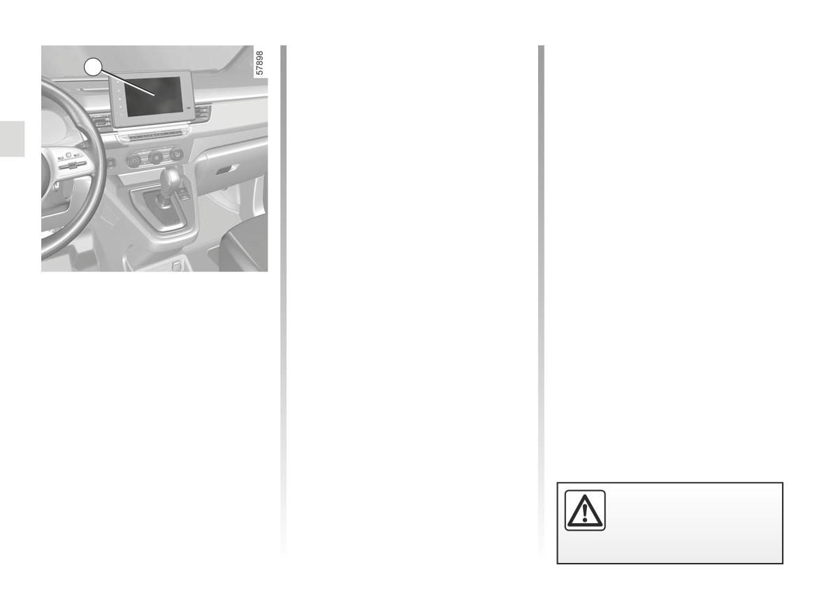
VEHICLE SETTINGS CUSTOMISATION MENU (1/3)
Adjusting the settings
d) “Welcome”:
1
- External welcome;
Select a menu then the function to be
- Automatic fold-out of mirrors;
modified (the display depends on the
- Interior welcome;
vehicle equipment and country):
- Courtesy light auto mode.
a) “Driving”:
Depending on the function, select:
- Indicator volume;
- “ON” or “OFF” to activate or deacti-
b) “Access”:
vate,
- Release driver’s door;
or
– Lock doors during driving;
- a duration to adjust the time the lights
– Opening/closing in “hands-free”
are switched on (for the “Follow-me-
mode;
home lighting” function for example).
– Remote locking/Approach
un-
Please refer to the multimedia instruc-
locking;
tions for further information.
- Distance locking sound;
- Silent mode;
Depending on the vehicle equipment,
- Automatic locking;
this function allows you to activate/de-
c) “Wiping and lighting”:
activate and adjust some of the vehi-
- Follow-me-home lighting;
cle’s functions.
- Wiping in reverse;
- Automatic front wiping;
Vehicles fitted with a
- Wiping after washing;
multimedia screen 1
Accessing the settings menu
Refer to the various multimedia instruc-
tions for information on accessing the
settings.
For safety reasons, carry
out any adjustments when
the vehicle is not being
driven.
1.138
CarManuals2.co
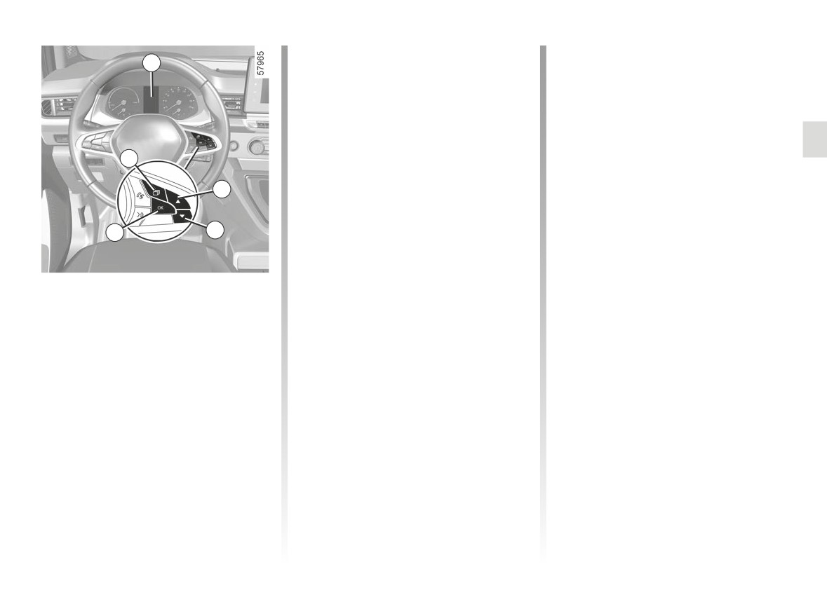
VEHICLE SETTINGS CUSTOMISATION MENU (2/3)
Adjusting the settings
d) “DRIVING ASSIST”:
2
- Lane departure warning sound
Navigate using the 4 or 5 control to
volume;
select the function to be modified and
- Lane departure warning sensitiv-
press 6 “OK” to confirm (display may
ity;
vary according to vehicle equipment
- Lane departure warning vibration;
and country):
- Lane keeping assist sensitivity;
a) “DASHBOARD”:
- Blind spot warning;
3
- Language;
- Active braking sensitivity;
- Unit;
- Advanced safety;
4
- Style;
- Overspeed warning;
- Colour;
- Distance warning;
5
b) “VEHICLE”:
e) “LIGHTING”:
6
- Rear windscreen wiping in re-
- Courtesy light auto mode;
verse gear;
- Automatic follow-me-home light-
- Automatic windscreen wiping;
ing;
Vehicles not fitted with a
- Front/rear drip wiping function;
- Follow-me-home lighting: XX sec-
multimedia screen
- External welcome;
onds;
f)
“ACCESS”:
c) “PARKING ASSIST”:
Accessing the settings menu on
- Lock doors during driving;
– Beep sound volume;
display 2
- Opening/Closing in “hands-free”
With the vehicle stopped, press the 3
mode;
switch as many times as required to
- Unlock the driver’s door only;
reach the “Vehicle” tab; Press repeat-
- Automatic re-locking;
edly on the 4 or 5 switch to access the
- Silent locking;
“Settings” menu, then confirm by press-
- Automatic opening/closing;
ing 6 “OK”.
- Automatic fold-out of mirrors;
g) “RESET”.
=
function activated
<
function deactivated
1.139
CarManuals2.co
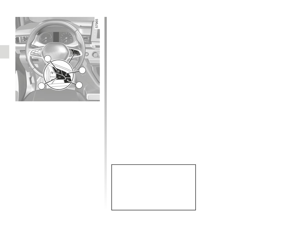
VEHICLE SETTINGS CUSTOMISATION MENU (3/3)
To exit the menu, press 4 or 5 to access
“BACK” and confirm by pressing 6
“OK”. It may be necessary to carry out
this operation more than once.
3
4
6
5
Once a line has been selected, press 6
“OK” to adjust the function.
If you select either “PARKING ASSIST”
then “VOLUME”, or “DASHBOARD”
then “LANGUAGE”, you will have to
make a further selection (sound volume
of the parking distance control or in-
strument panel language). In this case,
make your selection and confirm it by
pressing “6 OK”, the selected value is
shown by a =
in front of the line.
The vehicle settings personalisation
menu cannot be used when driv-
ing. At a speed exceeding 12 mph
(20 km/h), the instrument panel dis-
play switches automatically back to
trip computer and warning system
mode.
1.140
CarManuals2.co
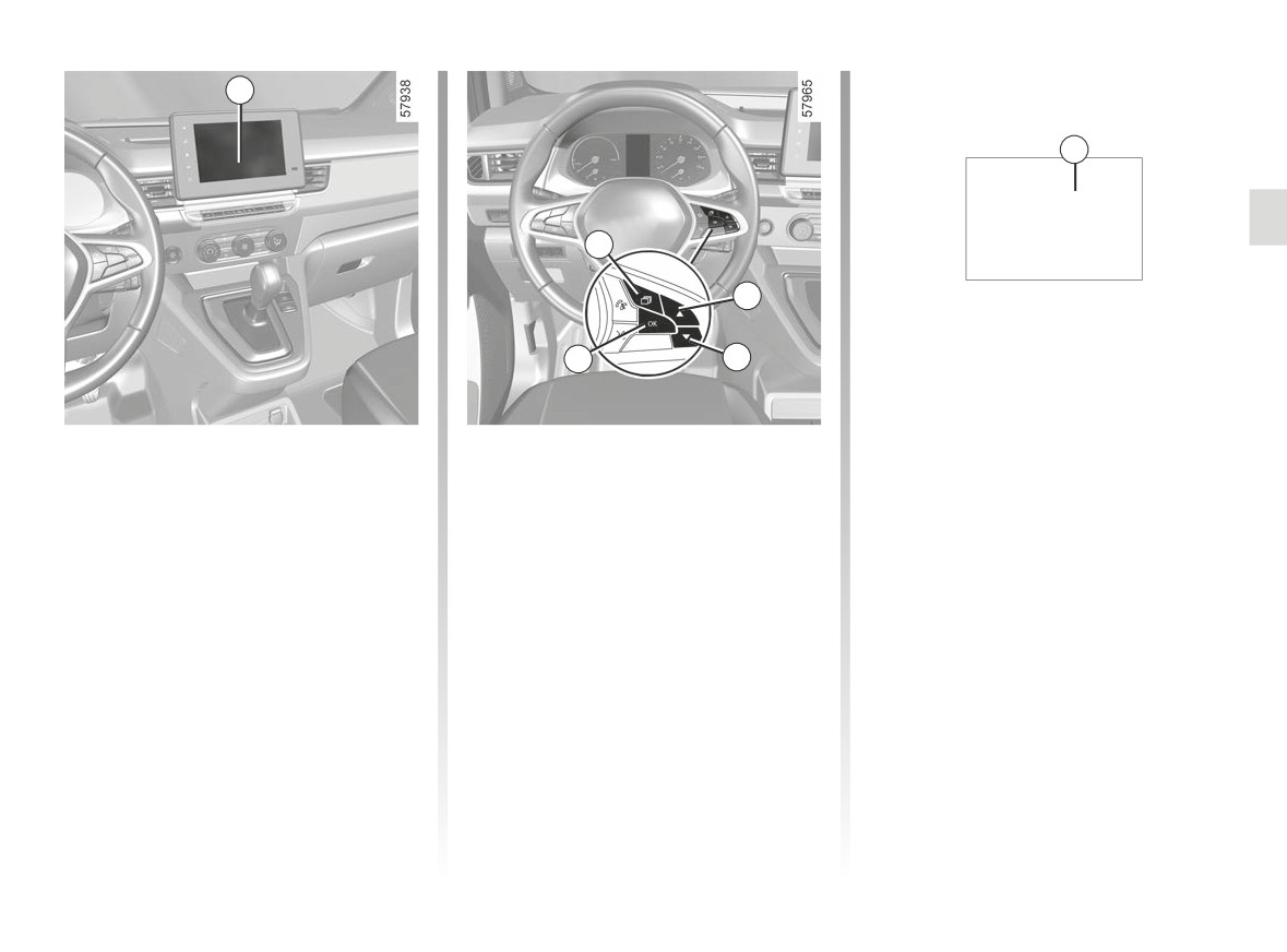
CLOCK AND EXTERIOR TEMPERATURE (1/2)
1
6
9°C 12:00
2
3
5
4
Vehicles fitted with a multimedia
Vehicles not fitted with a multimedia
Set the clock using control 3 or 4, then
screen
screen
press switch 5 “OK” to confirm.
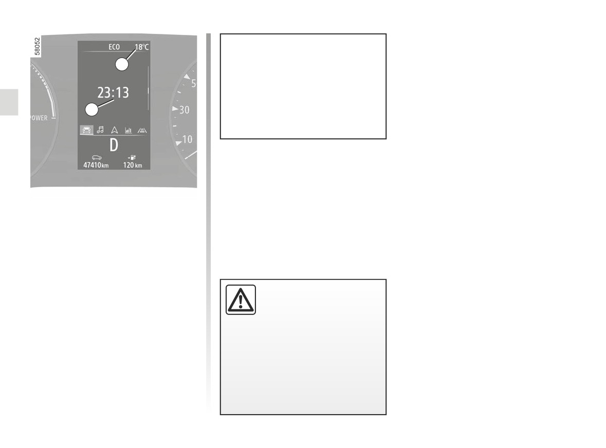
The time and exterior temperature are
Press the 2 switch as many times as re-
Set the minutes using control 3 or 4,
displayed on the multimedia screen 1.
quired to reach the “Vehicle” tab.
then press switch 5 “OK” to confirm.
Please refer to the multimedia instruc-
Repeatedly press control 3 or 4 to set
tions for further information.
the 6 clock.
Press and hold switch 5 “OK” until the
time display flashes.
1.141
CarManuals2.co
CLOCK AND EXTERIOR TEMPERATURE (2/2)
7
If the power supply is cut (battery
disconnected, supply wire cut, etc.),
the clock must be reset.
We recommend that you do not
6
adjust these settings while driving.
Exterior temperature
indicator 7
Special note:
When the external temperature is be-
tween -3°C and +3°C, the °C figures
flash (indicates risk of ice).
External temperature
indicator
As ice formation is related
to climatic exposure, local
air humidity and temperature, the
external temperature alone is not
sufficient to detect ice.
1.142
CarManuals2.co
STEERING-WHEEL, POWER-ASSISTED STEERING (1/2)
Activating the function
2
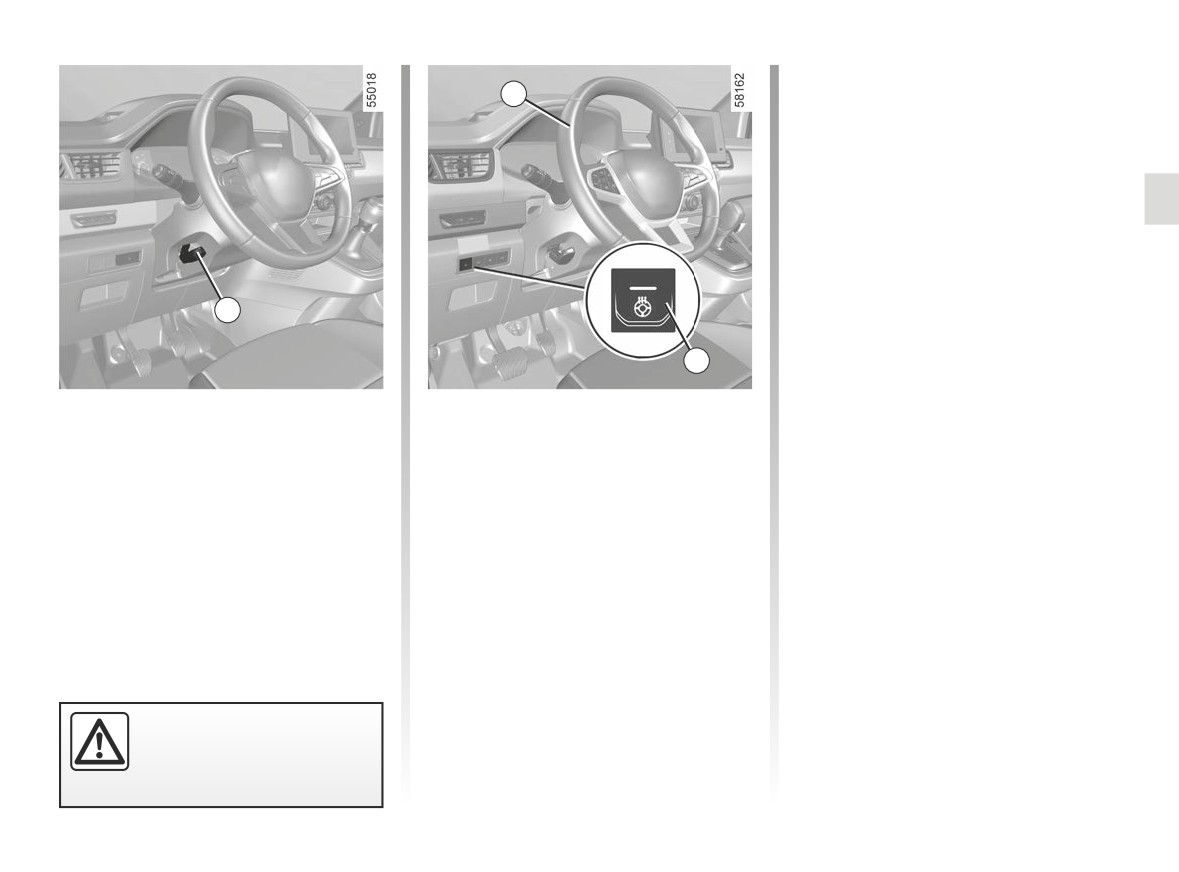
With the ignition on, press switch 3, the
indicator light in the switch lights up.
Deactivating the function
- Automatic:
The function switches off automatically
after the regulation phase of approxi-
mately 30 minutes. The indicator light
in switch 3 goes out.
1
Note: if the function has switched off
automatically, press the switch 3 twice
to reactivate it.
3
If switch 3 is not pressed again, the
function will be reactivated the next
Adjusting the steering wheel
Steering wheel heating
time the ignition is switched on.
height and depth
(depending on vehicle)
- Manually:
Lower the lever 1 and position the
This function heats the steering
steering wheel in the required position.
wheel 2.
To deactivate the function during the
regulation phase, press the switch 3.
Then, raise the lever fully, beyond the
Operating principle
The indicator light in switch 3 goes out.
point of resistance to lock the steering
When the temperature is reached, the
wheel.
function regulates the temperature of
Make sure that the steering wheel is
the heated areas for approximately
correctly locked.
30 minutes and then switches off auto-
matically.
For safety reasons, only
adjust the steering wheel
when the vehicle is station-
ary.
1.143
CarManuals2.co

STEERING-WHEEL, POWER-ASSISTED STEERING (2/2)
Power-assisted steering
Never drive with an inadequately
charged battery.
Variable power-assisted steering
The variable power assisted steering
system is equipped with an electronic
control system which alters the level of
assistance to suit the vehicle speed.
Steering is made easier during parking
manoeuvres (for added comfort) while
the force needed to steer increases
progressively as the speed rises (for
enhanced safety at high speeds).
Never leave the steering wheel on
full lock when the vehicle is station-
ary.
With the engine switched off, or if
there is a system fault, it is still pos-
sible to turn the steering wheel. The
force required will be greater.
Never switch off the igni-
A noise may be heard when the
tion when travelling down-
steering wheel is moved quickly.
hill, and avoid doing so in
This is normal.
normal driving (assistance
is not provided).
1.144
CarManuals2.co
REAR VIEW MIRRORS (1/4)
Folding rear view mirrors
Welcome and goodbye function
D
E
(depending on the vehicle)
(depending on the vehicle)
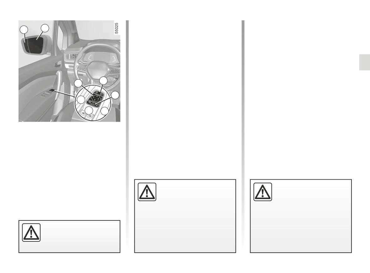
The door mirrors automatically fold in
Refer to the multimedia instructions to
when the vehicle is locked (switch 3 in
access the welcome and goodbye func-
position B).
tion.
In any case, you can make the door
Activate or deactivate the function by
mirrors fold in (switch 3 in position C) or
selecting (ON or OFF).
fold out (switch 3 in position A).
Depending on the selected choice, the
2
Automatic mode is then deactivated.
1
door mirrors will fold out:
To reactivate it, set the switch 3 to po-
- when the ignition is next switched on
sition B.
3
(function deactivated);
A
- when the card is detected or the ve-
hicle is unlocked (function activated).
B C
Exterior rear view mirrors
Adjustment
Select the rear view mirror using
switch 2, then use button 1 to adjust it
to the desired position.
Heated door mirrors
Mirror de-icing is carried out at the
Objects observed in the
The driver’s exterior rear
same time as rear screen de-icing.
door mirror glass are ac-
view mirror may have two
➥ 3.5 ➥ 3.9.
tually closer than they
clearly defined zones.
appear. For your safety,
Zone E shows what can
take this into account in order to
normally be seen in an ordinary rear
correctly assess the distance before
view mirror. Zone D increases rear
any manoeuvre.
side visibility.
For safety reasons, carry
out any adjustments when
the vehicle is not being
driven.
1.145
CarManuals2.co
REAR VIEW MIRRORS (2/4)
4
3
Manually folding door mirrors
Special case
Interior rear view mirror
When the rear view mirror has been
Its position can be adjusted.
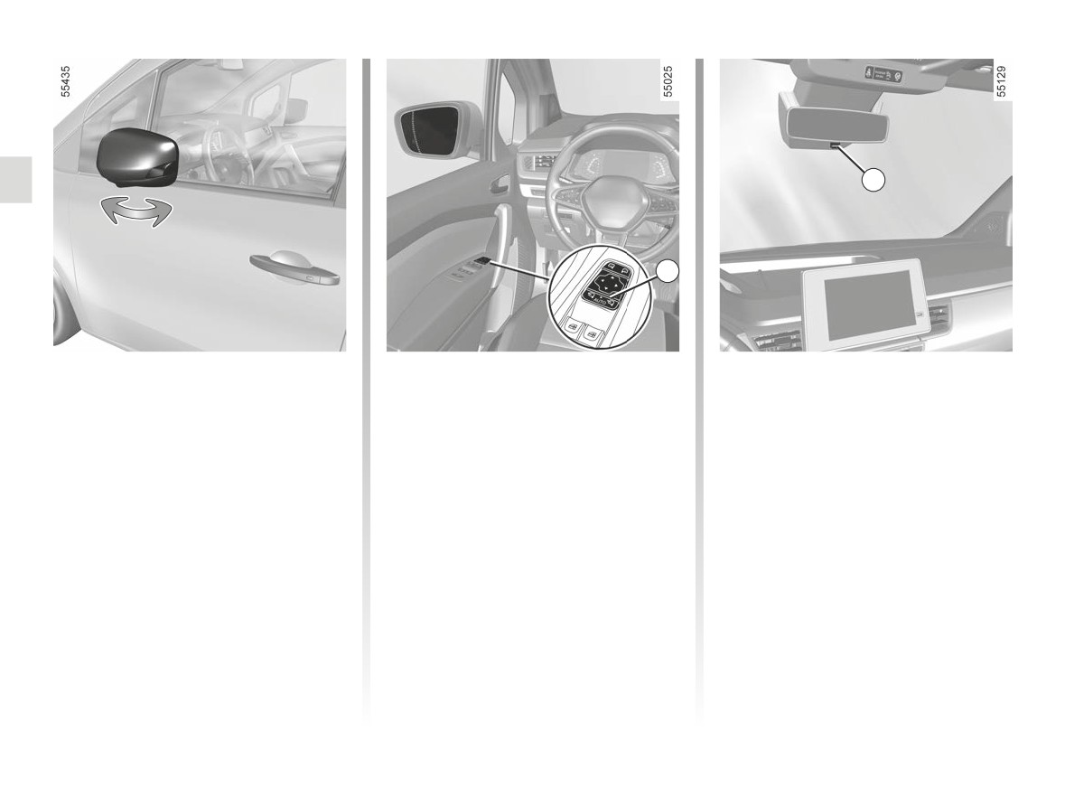
To fold down the door mirror, pull it to-
manually deployed or folded back, it is
wards the door window until you hear a
possible to reset it to a usage position.
Rear view mirror with lever 4
mechanical click.
When driving at night, to avoid being
To do this, press the 3 switch. A me-
To return the door mirror to its operating
dazzled by the headlights of the vehicle
chanical tapping noise can be heard
position, proceed in the reverse order.
behind, depress the little lever located
from the door mirror.
Ensure that it is correctly locked in po-
behind rear view mirror 4.
sition.
If a tapping noise cannot be heard,
press once again on 3 switch until the
Rear view mirror without lever 4
tapping noise can be heard from the
The rear view mirror automatically dark-
door mirror.
ens when you are being followed by a
vehicle which illuminates you or in very
bright lighting.
1.146
CarManuals2.co
REAR VIEW MIRRORS (3/4)
5
F
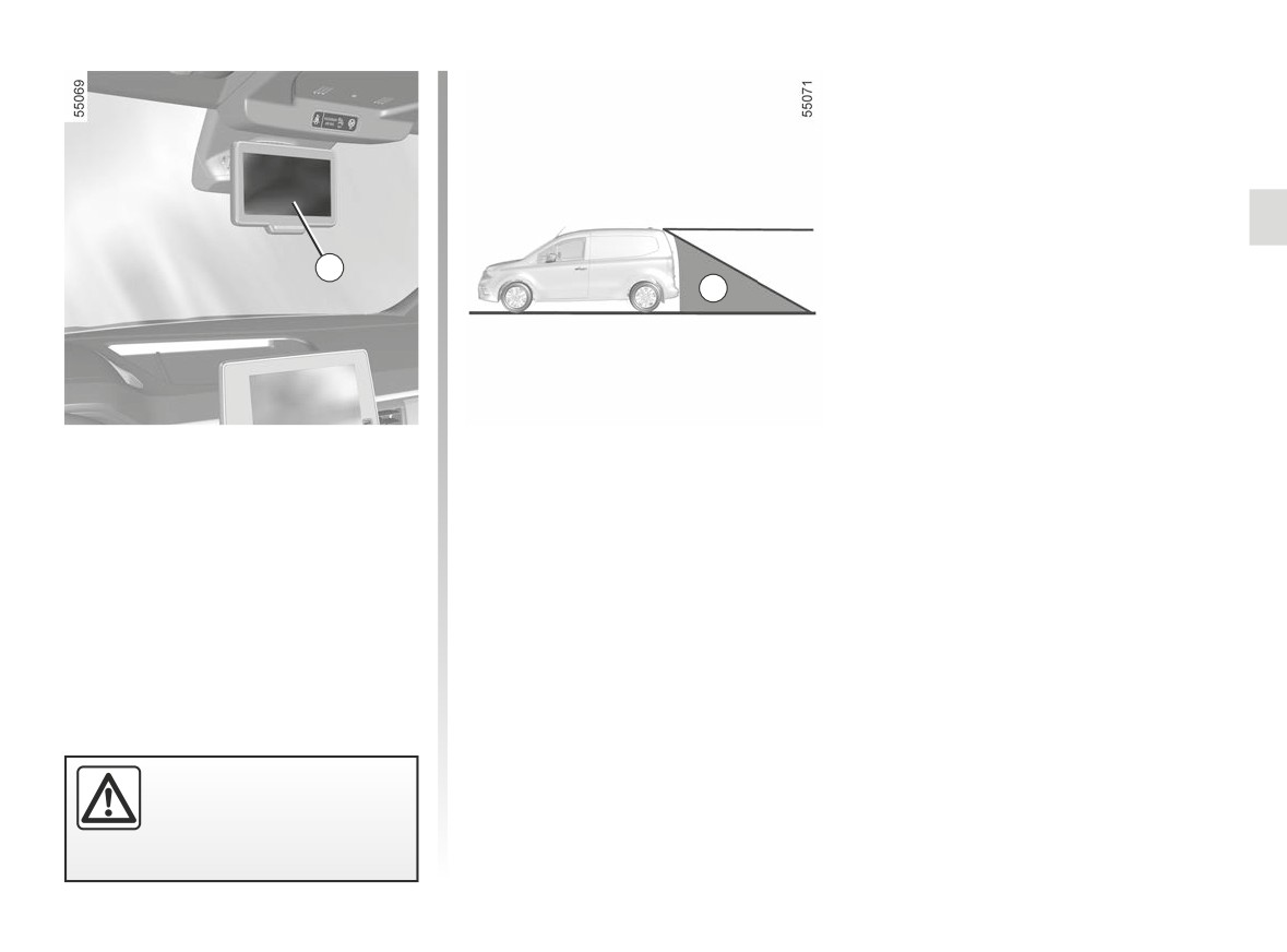
Camera rear view system
The camera’s field of vision does not
cover the entire area behind the vehi-
screen
cle, particularly the blind spot area F.
The screen 5 can be positioned left
to right and upwards and downwards
➥ 1.149.
For safety reasons, carry
out any adjustments when
the vehicle is not being
driven.
1.147
CarManuals2.co
REAR VIEW MIRRORS (4/4)
G
H
H
7
6
I
G
I
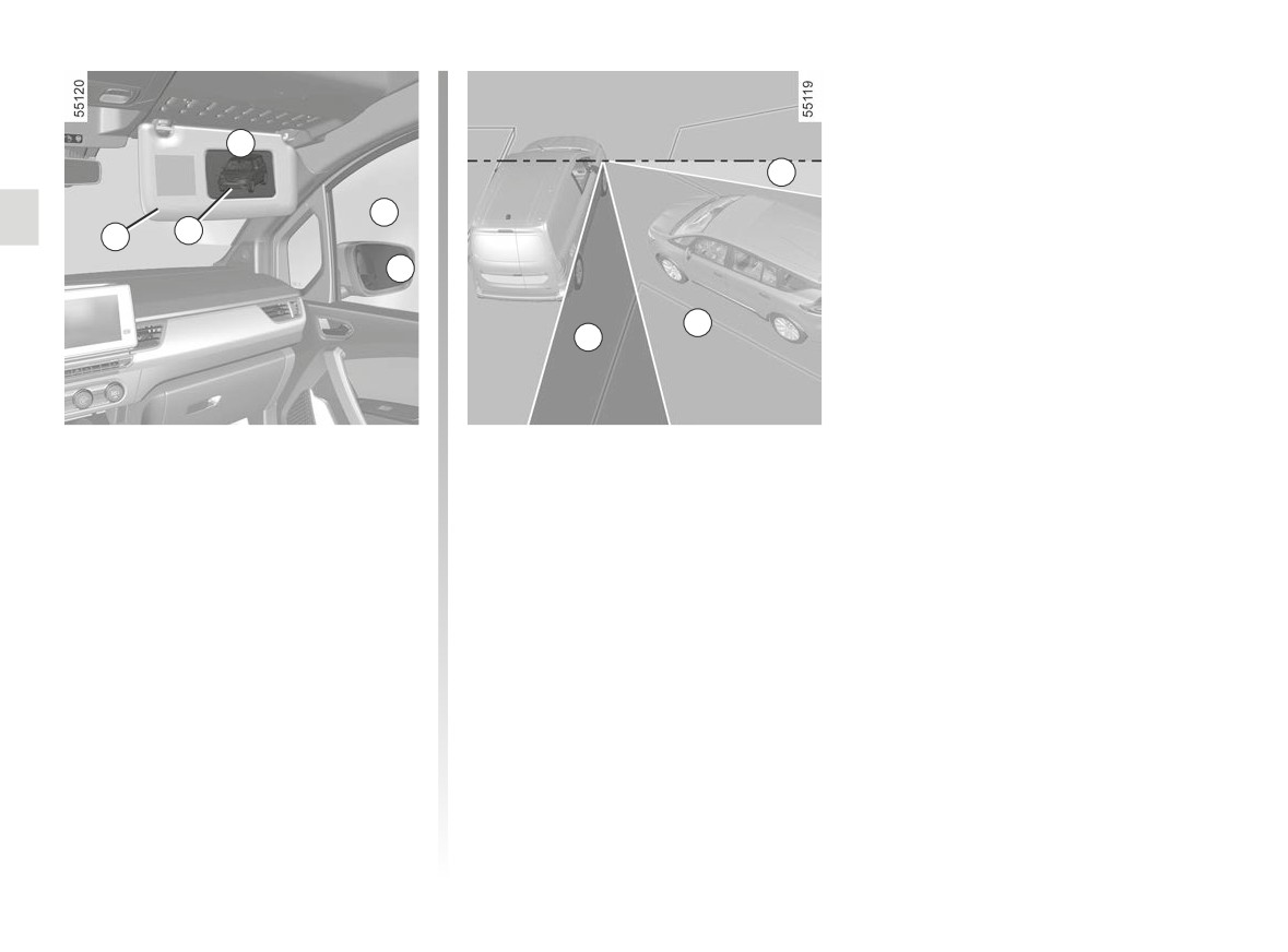
Wide angle rear view mirror 7
The various zones seen by the driver
(depending on the vehicle)
are:
- G in the wide-angle rear view mirror;
Lower the sun visor 6 to access the
- H via the front passenger window;
special mirror to increase side vision
- I in the exterior rear view mirror.
when manoeuvring.
1.148
CarManuals2.co