Renault Clio (2023 year). Manual in english - page 7
MOTORWAY AND TRAFFIC ASSISTANT (16/16)
Some conditions can disrupt or damage the operation of the system, for example:
- obstruction of the windscreen or the radar area (by dirt, ice, snow, condensation etc.) Frequently check the cleanli-
ness and condition of the windscreen, front wiper blades and front bumper;
- a complex environment (tunnel etc.);
- poor weather conditions (snow, heavy rain, hail, black ice, etc.);
- poor visibility (night, fog etc.);
- poor contrast between the vehicle preceding it and the surrounding area (e.g. white vehicle in a snowy area etc.) ;
- being dazzled (glaring sun, lights of vehicles travelling in the opposite direction etc.);
- narrow, winding or undulating road (tight bends etc.);
- the tar lines detected as a line by the system;
- narrowing/widening lanes;
- road markings which are worn, lacking in contrast or very widely spaced from one another (lines partially erased etc);
- multiple markings on the road (roadworks area, slip roads connecting to adjacent motorways, hard shoulder etc.);
- a slower vehicle with a significant difference in speed;
- use of mats not adapted to the vehicle. On the driver’s side, only use mats suitable for the vehicle, attached with the pre-
fitted components, and check the fitting regularly. Do not lay one mat on top of another. There is a risk of wedging the
pedals.
In these cases, the system may wrongly intervene.
- Risk of unwanted braking or acceleration.
- Risk of unwanted, incorrect correction or no correction of trajectory.
Many unforeseen situations may affect the system operation. Certain objects or vehicles that can appear in the camera or
radar detection zone may be interpreted by the system incorrectly, possibly leading to inappropriate acceleration or braking.
You should always be attentive to sudden events that might occur while you are driving. Always maintain your vehi-
cle under control by keeping your feet near the pedals and your hands on the steering wheel, so that you are ready
to act in any event.
2.130
CarManuals2.co
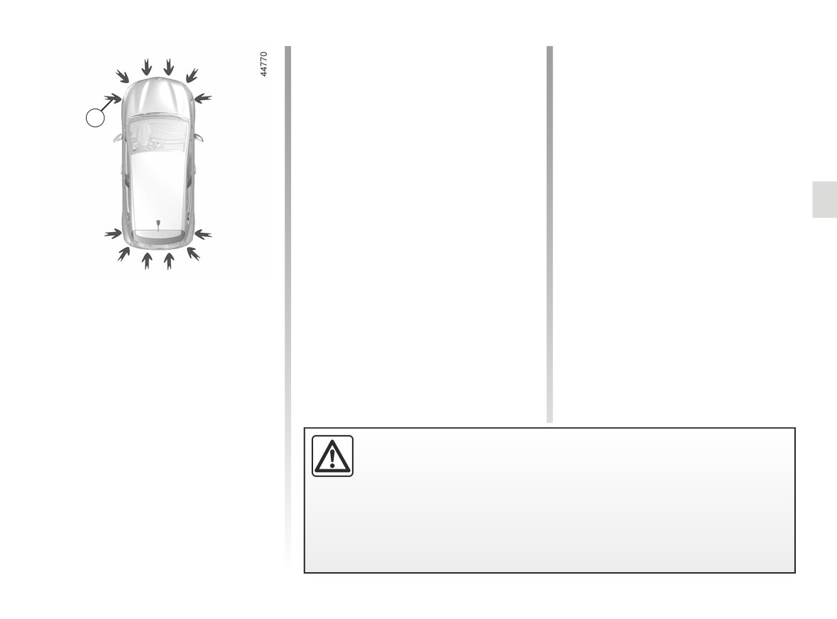
PARKING DISTANCE CONTROL (1/7)
Depending on the vehicle, the system
Location of the ultrasonic
detects obstacles to the front, the rear
sensors 1
and the sides of the vehicle.
Ensure that the ultrasonic sensors indi-
The parking distance control system
cated by the arrows 1 are not obscured
1
is only activated when the vehicle is
(by dirt, mud, snow, a badly fitted/at-
driven at a speed below approximately
tached number plate), impacted, mod-
6 mph (10 km/h).
ified (including paintwork) or obstructed
The function does not take into account
by any accessory fitted to the rear and/
towing or carrying systems that are not
or, depending on the vehicle, to the
recognised by the system.
front or sides of your vehicle.
This measurement is indicated by
beeps which become more frequent the
closer you come to the obstacle, until
they become a continuous beep when
the vehicle is approximately
20 to
Operating principle
30 centimetres from the obstacle.
Ultrasonic sensors, indicated
by
arrows 1, are fitted in the bumpers to
measure the distance between the ve-
hicle and an obstacle.
This function is an additional driving aid.
Under no circumstances should it replace the driver’s care or responsibil-
ity whilst reversing.
The driver should always be ready for sudden incidents while driving: always
ensure that there are no small, narrow moving obstacles (such as a child, animal,
pushchair, bicycle, stone, post, etc.) in the blind spot when manoeuvring.
2.131
CarManuals2.co
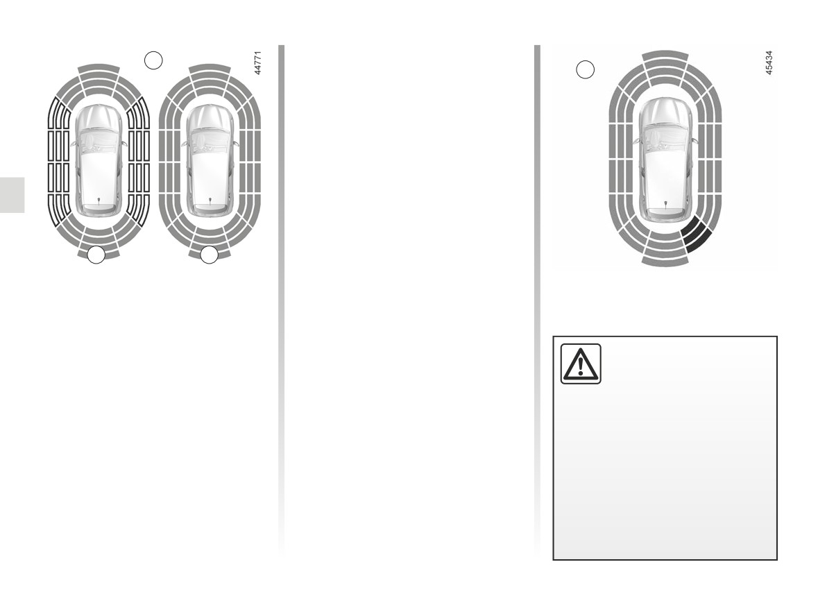
PARKING DISTANCE CONTROL (2/7)
Note: for vehicles fitted with the “360°
2
camera” function ➥ 2.71, analysis of the
C
vehicle surroundings (areas A and B)
is not displayed in “Bird’s eye view” or
“Side view” mode.
Operation
Most objects located less near the
front, rear and sides of the vehicle are
detected.
Depending on the distance of the ob-
stacle, the frequency of the beep will
be higher while approaching it, and
A
B
will become a continuous beep around
20 cm away for obstacles to the sides,
Note: the display 2 shows the vehicle
and around 30 cm for obstacles to the
surroundings and emits beeps.
front or rear. The green, orange (or
It is necessary to travel a few metres
yellow depending on the vehicle) and
before the side detection is activated.
red zones will be shown on the C dis-
play.
If all areas have a grey background, the
An impact to the under-
whole area around the vehicle is being
Note: in the event of a change in tra-
side of the vehicle while
monitored:
jectory during a manoeuvre, the risk of
manoeuvring
(e.g. strik-
collision with an obstacle may be sig-
ing a post, raised kerb or
- A: analysis of the vehicle surround-
nalled late.
other street furniture) may result in
ings in progress;
damage to the vehicle (e.g. defor-
- B: analysis of the vehicle surround-
mation of an axle).
ings carried out.
To avoid any risk of accident, have
your vehicle checked by an ap-
proved dealer.
2.132
CarManuals2.co
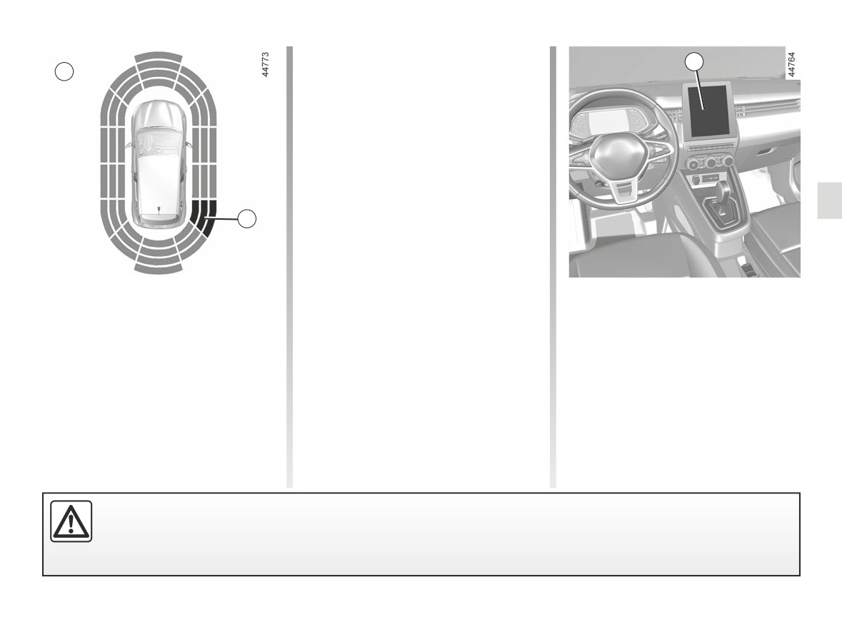
PARKING DISTANCE CONTROL (3/7)
If a side obstacle is detected:
4
D
- the beeps become faster and then
sound continuously as the obstacle
gets nearer. Green, orange and red
zones will be displayed on the dis-
play D;
- if there is no risk of collision, no beep
will sound when approaching the ob-
stacle. Green, orange and red zones
will be displayed interspersed on the
display D.
3
Note: in the event of a change in tra-
jectory during a manoeuvre, the risk of
collision with an obstacle may be sig-
nalled late.
Detection of obstacles to the side
Activation/deactivation
Depending on the direction of the
Vehicles fitted with a multimedia
wheels, the system determines the tra-
screen 4
jectory of the vehicle and notifies the
driver of any risk or otherwise of a col-
To activate or deactivate the various
lision with an obstacle 3 to the side of
zones covered by the ultrasonic detec-
the vehicle.
tors from the multimedia screen, refer
to the multimedia instructions.
Select “ON” or “OFF”.
An impact to the underside of the vehicle while manoeuvring (e.g. striking a post, raised kerb or other street furniture)
may result in damage to the vehicle (e.g. deformation of an axle).
To avoid any risk of accident, have your vehicle checked by an approved Dealer.
2.133
CarManuals2.co
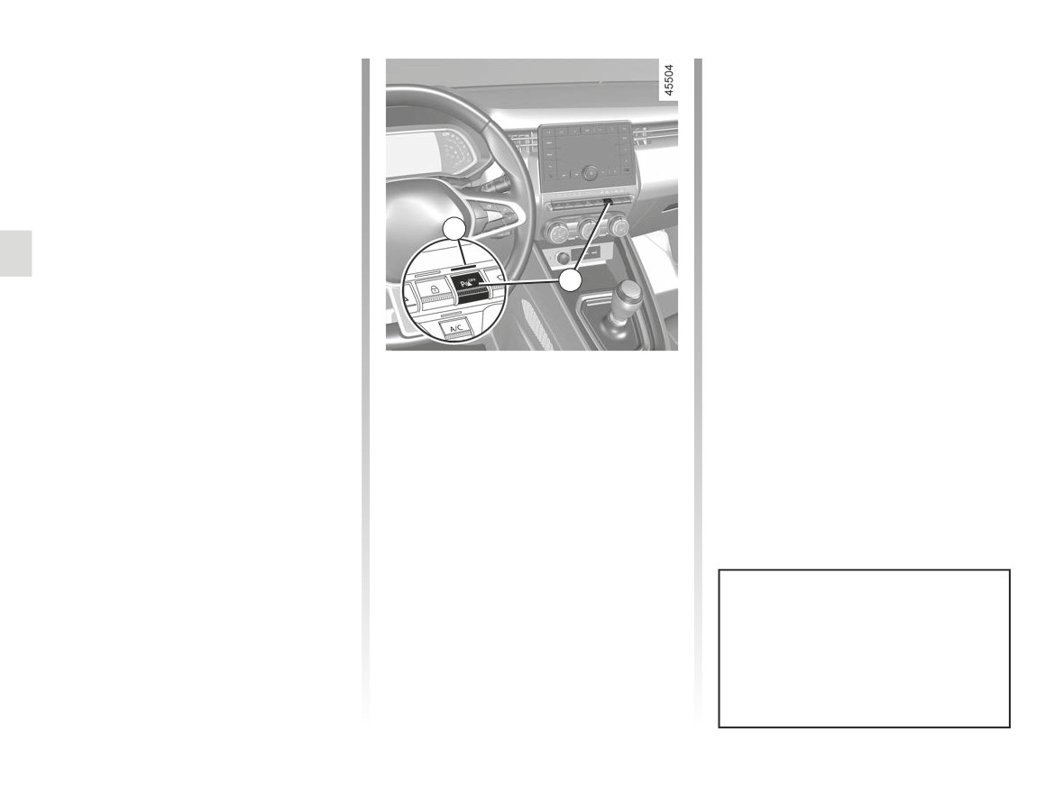
PARKING DISTANCE CONTROL (4/7)
Vehicles not fitted with a multimedia
screen
With the vehicle stopped, press the 6
switch to deactivate parking distance
control. The switch warning light illu-
minates. Press again on the 6 switch
to activate the function. The switch 5
warning light goes out.
5
Adjustment
6
Vehicles fitted with a multimedia
screen 4
Depending on the vehicle, with the
engine running, some settings can be
System sound
adjusted from the multimedia screen 4.
Enables the system sound
to
be
Please refer to the multimedia instruc-
chosen.
tions for further information.
Deactivating the system sound
Parking distance control audio
Activate or deactivate the parking dis-
volume
tance control sound.
Adjust the volume of the parking dis-
Note: if you deactivate the sound, you
tance control by pressing + or -.
will no longer be notified with beeps
when approaching an obstacle.
When the vehicle is travelling at a
speed below approximately 6 mph
(10 km/h), some noises (motorcy-
cle, lorry, pneumatic drill etc.) may
trigger the beeping sound of the
parking distance control.
2.134
CarManuals2.co
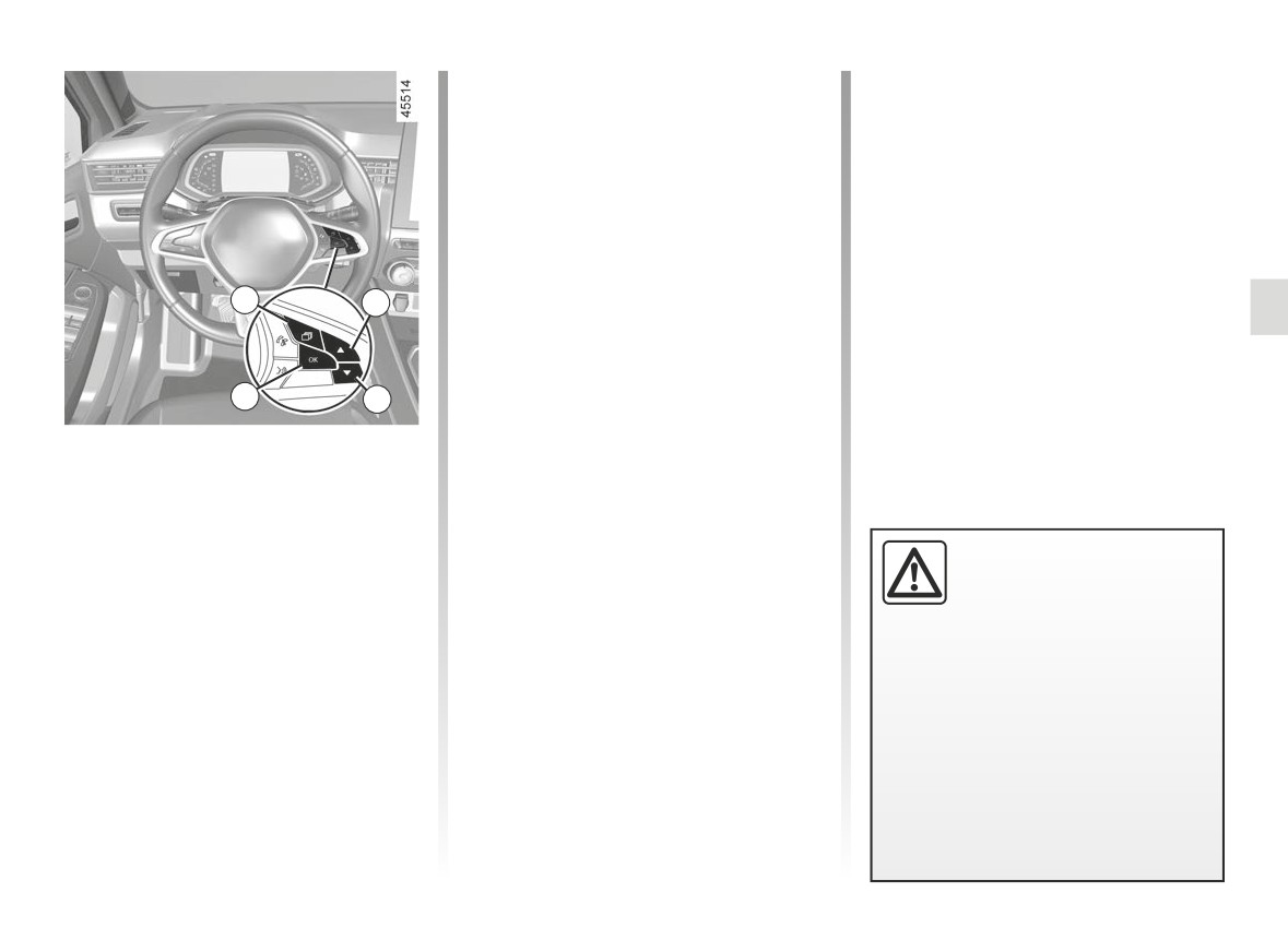
PARKING DISTANCE CONTROL (5/7)
- select “BIP VOLUME” to adjust the
- when an operating fault is detected.
Park Assist volume using the 8 or 9
Note: if the vehicle is fitted with a
control.
towbar recognised by the system, only
the rear Park Assist function is deacti-
vated.
Deactivating the parking
distance control manually
You must disable the function if:
Operating faults
- if towing, carrying or trailer equip-
When the system detects an operating
ment that is unrecognised by the
fault, a beep sounds for approximately
7
8
system is present in front of the ul-
three seconds each time reverse gear
trasonic sensors;
is selected and the message “Check
- in the event of damage to the ultra-
parking distance control” appears on
sonic sensors.
the instrument panel. Consult an ap-
proved dealer.
10
9
Parking distance control
Vehicles not fitted with a multimedia
automatic deactivation
screen
The system deactivates:
- With the vehicle stopped, press the 7
- when the vehicle speed is above
switch as many times as required to
approximately 6 mph (10 km/h);
reach the “Vehicle” tab;
- depending on the model, when the
An impact to the under-
– press the 8 or 9 control repeatedly
vehicle is stationary for more than
side of the vehicle while
to reach the “Settings” menu. Press
approximately 5 seconds and an ob-
manoeuvring
(e.g. strik-
the switch 10 OK;
stacle is detected (such as when in
ing a post, raised kerb or
– press the 8 or 9 control repeatedly
a traffic jam, etc.);
other street furniture) may result in
to reach the “PARKING ASSIST”
- when the vehicle is in neutral on
damage to the vehicle (e.g. defor-
menu. Press the switch 10 OK;
manual gearboxes, or in position N
mation of an axle).
or P on automatic gearboxes;
To avoid any risk of accident, have
your vehicle checked by an ap-
proved dealer.
2.135
CarManuals2.co
PARKING DISTANCE CONTROL (6/7)
System servicing/repairs
- In the event of an impact, the alignment of the sensors may be altered and their operation may consequently be affected.
Deactivate the function and consult an authorised dealer.
- Any work in the area where the sensors are located (repairs, replacements, etc.) must be carried out by a qualified profes-
sional.
Only an authorised dealer is qualified to service the system.
System disturbance
Some conditions can disrupt or damage the operation of the system, for example:
- poor weather conditions (rain, snow, hail, black ice, etc.);
- in the event of exposure to strong electromagnetic waves (under high-voltage lines, etc.);
- some types of noise (motorcycle, lorry, pneumatic drill etc.);
- fitting an unsuitable towing ball or hook.
Risk of false alarms or absence of warnings
In the event of the system behaving abnormally, deactivate it and consult an authorised dealer.
2.136
CarManuals2.co
PARKING DISTANCE CONTROL (7/7)
Limitation of the system operation
- The area around the sensors must be kept clean and free of any modifications in order to ensure the proper operation of the
system.
- Small objects moving close to the vehicle (motorcycles, bicycles, pedestrians, etc.) may not be recognised by the system.
- The system may not detect objects that are too close to the vehicle.
- The system may not provide a warning when the other vehicles or objects are travelling at a significantly different speed.
- During a change in trajectory, during a manoeuvre, the system may report obstacles with a delay.
- When the vehicle is towing a trailer, the rear Park Assist system must be deactivated
Deactivating the function
You must disable the function if:
- the area around the sensors has been damaged (rear bumper);
- the vehicle is equipped with a towing device that is not recognised by the system (ball, hook, adapter, etc.).
2.137
CarManuals2.co
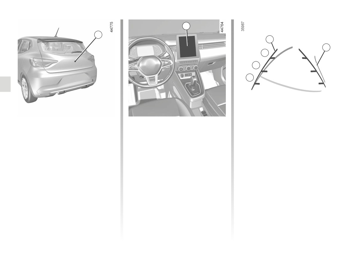
REVERSING CAMERA (1/2)
2
1
3
4
C
B
A
Operation
Fixed clearance gauge 3
4 moving guide line:
When the vehicle is reversing, the
The fixed clearance gauge comprises
This is shown in blue on the multime-
camera 1 on the luggage compart-
coloured markers A, B and C indicating
dia screen 2. It indicates the vehicle tra-
ment lid transmits a view of the area
the distance behind the vehicle:
jectory according to the position of the
surrounding the rear of the vehicle to
steering wheel.
- A(red) approximately 30 centimetres
the multimedia display 2 accompanied
from the vehicle;
by two guiding lines 3 and 4 (fixed and
- B(yellow) approximately 70 centime-
Special feature
mobile).
tres from the vehicle;
Make sure that the camera is not ob-
This system uses several guidelines for
- C(green) approximately 150 centi-
scured (by dirt, mud, snow, condensa-
its operation (mobile for trajectory and
metres from the vehicle.
tion etc.).
fixed for distance). When the red zone
This gauge remains fixed and indicates
is reached, use the bumper image to
the vehicle trajectory if the wheels are
stop accurately.
in line with the vehicle.
2.138
CarManuals2.co
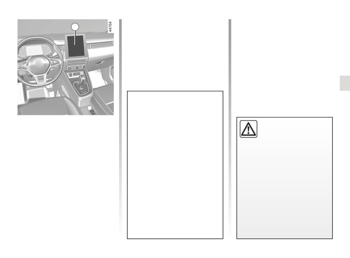
REVERSING CAMERA (2/2)
2
The screen shows a reverse mirror
image.
Settings
This function is an additional
The frames are a representation
With the vehicle stationary and the
aid. It cannot, therefore,
projected on a flat surface. This in-
engine running, from the multime-
under any circumstances
formation is to not be taken into ac-
dia screen 2 you can add or remove
replace the vigilance or the
count when superimposed on a
the guide lines and adjust the camera
responsibility of the driver.
vertical object or an object on the
image settings (brightness, contrast
The driver should always be ready
ground.
etc.). Please refer to the multimedia in-
for sudden incidents while driv-
structions for further information.
Objects which appear on the edge
ing: always ensure that there are
of the screen may be deformed.
no small, narrow moving obstacles
In very bright light (snow, vehicle in
(such as a child, animal, pushchair,
sunshine, etc.), the camera vision
bicycle, stone, post, etc.) in the blind
may be adversely affected.
spot when manoeuvring.
If the boot is open or poorly closed,
the message
“WARNING: Boot
Open” appears and the camera dis-
play disappears.
2.139
CarManuals2.co
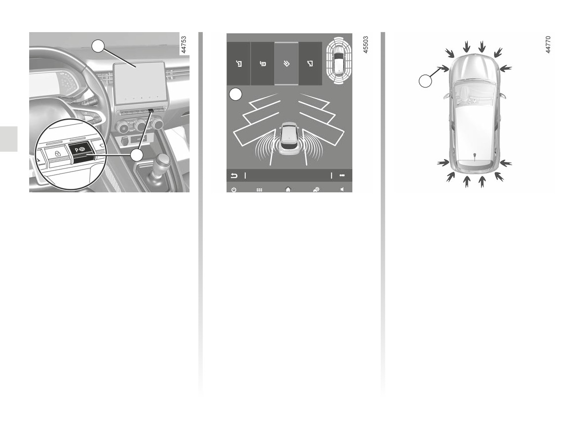
ASSISTED PARKING (1/5)
1
3
A
2
Using ultrasonic detectors as indicated
Switching on
Special features
by the 3 arrows installed in the vehicle
With the vehicle stationary or driving
Ensure that the ultrasonic sensors indi-
bumpers, this function helps to find ac-
at less than approximately
19 mph
cated by the 3 arrows are not obscured
cessible parking spaces and assists in
(30 km/h):
(by dirt, mud, snow, a badly fitted/at-
the parking manoeuvre.
tached number plate), impacted, modi-
- press switch 2. The indicator light in
Remove your hands from the steering
fied (including paintwork) or obstructed
switch 2 lights up and display A ap-
wheel, you only control:
by any accessory fitted to the front or
pears on the multimedia screen 1;
rear of your vehicle.
- the accelerator pedal;
- set the direction indicators to the
- the brake pedal;
side of the vehicle where you want to
park.
- the gear lever.
At any time, you can regain control by
using the steering wheel.
2.140
CarManuals2.co
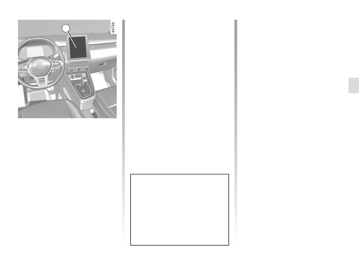
ASSISTED PARKING (2/5)
Note: when starting the vehicle, or after
Operation
1
having successfully completed parallel
parking using the system, the default
Parking
manoeuvre proposed by the system is
As long as the vehicle speed is less
assistance in exiting a parallel parking
than 19 mph (30 km/h), the system
space. In other cases, the default ma-
searches for available parking spaces
noeuvre can be set from the multimedia
on the side of the vehicle chosen by the
screen 1. Please refer to the multime-
driver.
dia instructions for further information.
Note: if parking spaces are available
on the other side of the vehicle, set the
direction indicators to the other direc-
tion to enable the system to search for
spaces.
Once a space has been found, it is dis-
played on the multimedia screen, indi-
Choice of manoeuvre
cated by a small letter “P”. Drive slowly,
with the direction indicators activated
The system can perform four types of
on the side where the space is avail-
manoeuvres:
able, until the message “Stop” is dis-
- parallel parking;
played and a beep sounds.
- perpendicular parking;
- angle parking;
- moving out of a parallel parking
space.
From the 1 multimedia screen, select
the manoeuvre to carry out.
The system start up is accompa-
nied by activation of the parking dis-
tance control and, on those vehicles
equipped, the reversing camera or
360° camera to help the driver vis-
ualise the manoeuvre. ➥ 2.131,
➥ 2.138 and ➥ 2.71.
2.141
CarManuals2.co
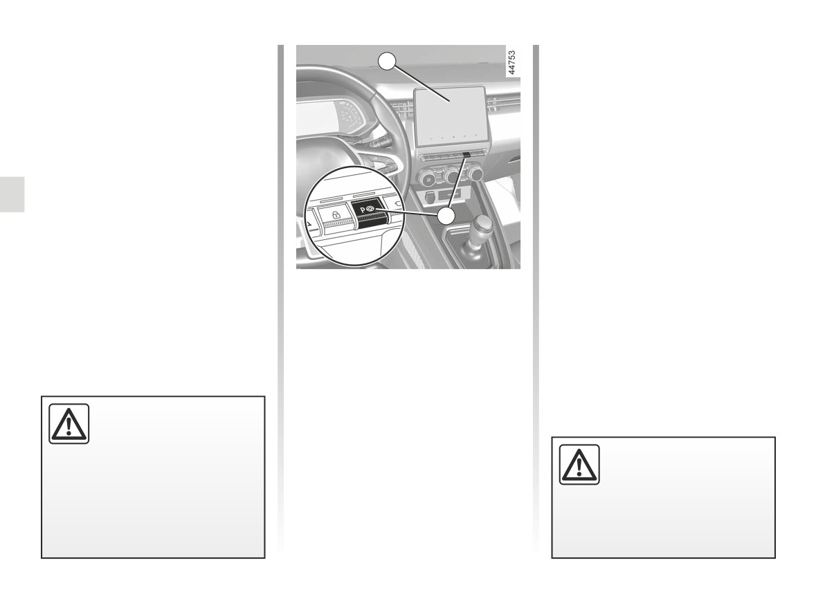
ASSISTED PARKING (3/5)
The space is then indicated on the mul-
- Release the steering wheel;
timedia screen by a capital letter “P”.
1
- carry out manoeuvres at the front
- Stop the vehicle;
and rear by following the instructions
shown on the multimedia screen 1
- select reverse gear.
and using the parking distance con-
trol system alerts.
The indicator light
lights up
on the instrument panel and a beep
Your speed should not exceed around 4
sounds.
mph (7 km/h).
- Release the steering wheel;
Once the vehicle is in a position to exit
- follow the instructions shown on the
the parking space, the
warning
multifunction screen 1.
2
light disappears from the instrument
Your speed should not exceed around 4
panel and a sound signal and message
mph (7 km/h).
appear on the multimedia screen 1 to
confirm that the manoeuvre is com-
Exiting a parallel parking space
plete.
Once the warning light
on the
instrument panel goes off and a beep
- Briefly press the 2 switch;
sounds, the manoeuvre has been com-
- select “Exit parallel parking space”
pleted.
mode;
- activate the direction indicators on
the side you wish to go out of;
- press and hold switch 2 (approx. two
seconds).
This function is an addi-
The indicator light
lights up
tional driving aid.
on the instrument panel and a beep
Therefore, it can under no
sounds.
When manoeuvring, the
circumstances replace the
steering wheel may turn
driver’s vigilance and responsibility
quickly: do not put your
during manoeuvres (the driver must
hands inside, and make
always be ready to brake).
sure that nothing is caught inside.
2.142
CarManuals2.co
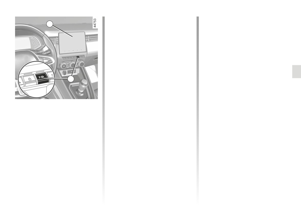
ASSISTED PARKING (4/5)
The warning light on the 2 switch turns
Cancelling the manoeuvre
1
off, the
warning light disappears
The manoeuvre is cancelled in the fol-
from the instrument panel and a sound
lowing cases:
signal confirms that the manoeuvre has
- the vehicle speed has exceeded 4
been suspended. The reason for sus-
mph (7 km/h);
pending the manoeuvre will be dis-
- by pressing switch 2;
played on the multimedia screen 1.
- you have performed more than ten
Make sure:
forwards/backwards movements in
- you have released the steering
one manoeuvre;
wheel;
- the parking distance control sensors
2
and
are dirty or blocked;
- that all doors and the boot are closed;
- the vehicle wheels have skidded;
and
- the manoeuvre has been suspended
- that no obstacles are in the way of
Suspending/Resuming the
for too long.
the direction of movement;
manoeuvre
The 2 switch warning light and the
and
The manoeuvre is suspended in the fol-
- that the engine is started.
warning light disappear from the
lowing circumstances:
If the warning light on the 2 switch
instrument panel and a sound signal
- you take control of the wheel;
flashes, this indicates that the system
confirms that the manoeuvre has been
is once again available to resume the
cancelled. The reason for cancelling
- the vehicle is stationary for too long;
manoeuvre.
the manoeuvre will be displayed on the
- an obstacle in the direction of move-
multimedia screen 1.
To resume the manoeuvre, press and
ment prevents the manoeuvre from
hold the 2 switch. The 2 switch warning
being completed;
- the engine stops;
light appears and
warning light
is displayed on the instrument panel.
- a door or the luggage compartment
is opened.
Follow the instructions shown on the
multimedia screen 1.
2.143
CarManuals2.co
ASSISTED PARKING (5/5)
This function is an additional driving aid. This function is not under any circumstances intended to replace the due care
and attention of the driver, who should at all times be in control of the vehicle. Make sure that the manoeuvre complies
with the applicable traffic regulations in your location.
The driver should always be ready for sudden incidents while driving: always ensure that there are no small, narrow
moving obstacles (such as a child, animal, pushchair, bicycle, stone, post, towing equipment, etc.) in the blind spot when
manoeuvring.
System servicing/repairs
- In the event of an impact, the alignment of the sensors may be changed and their operation may consequently be affected.
Deactivate the function and consult an authorised dealer.
- Any work in the area where the sensors are located (repairs, replacements, exterior trim modifications, etc.) must be carried
out by a qualified professional.
Only an authorised dealer is qualified to service the system.
In the event of system disturbance
Certain conditions may disrupt or impair operation of the system, such as poor weather conditions (snow, hail, ice, etc.).
In the event of the system behaving abnormally, deactivate it and consult an authorised dealer.
Risk of erroneous false alarms.
Limitations of the system operation
- The system cannot detect objects located in the sensor blind spots.
- Always visually check that the parking space proposed by the system is still available and contains no obstacles.
- The system should not be used when towing a trailer or when there is a towing or load carrying system on the vehicle or on
surrounding vehicles.
2.144
CarManuals2.co
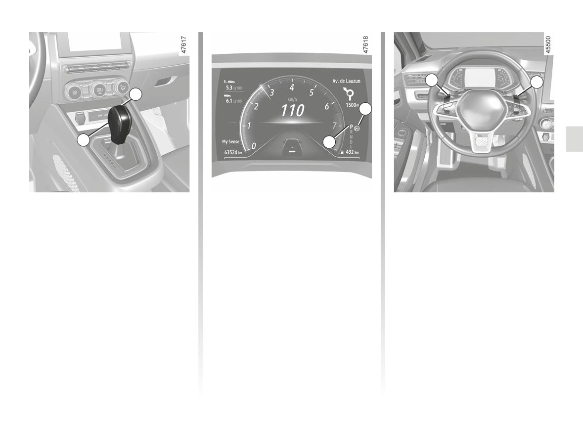
AUTOMATIC TRANSMISSION (1/4)
5
6
1
3
2
4
Selector lever 1
Operation
Gear changing paddles 5
P: park
With gear lever 1 in position P, start the
and 6
R: reverse
engine.
Depending on the vehicle, you can use
N: Neutral
paddles 5 and 6 to change gear when
To move out of position P, you must de-
D: automatic mode
the lever is in position D.
press the brake pedal before pressing
L: “Low” mode (depending on the ve-
5: Change to a lower gear.
the unlocking button 2.
hicle)
6: Change to a higher gear.
With your foot on the brake pedal (warn-
The 4 display on the instrument panel
Positions P, N, L and R cannot be ac-
ing light 3 disappears from the display),
indicates the gear lever position en-
cessed using the paddles.
shift out of P position, release the lock-
gaged 1.
ing button 2 and engage D position.
Note: press the 2 button to:
Only engage D or R when the vehi-
- exit position P;
cle is stopped, with your foot on the
- switch from position D, L or N to R or
brake and the accelerator pedal re-
P;
leased.
– switch from position D to L.
2.145
CarManuals2.co
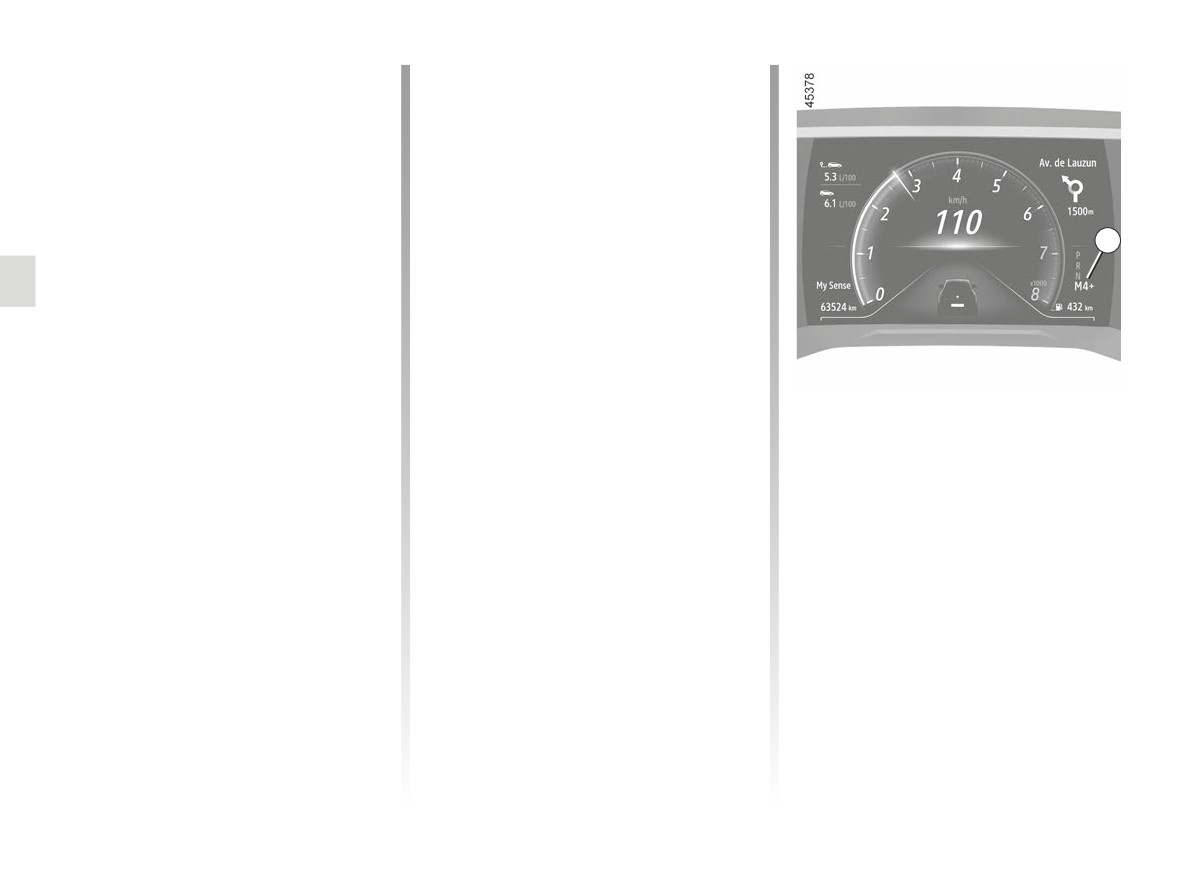
AUTOMATIC TRANSMISSION (2/4)
Driving in automatic mode
Driving in manual mode
Put lever 1 into position D.
When driving in position D you can
switch to manual driving mode using
In most road conditions you will en-
paddles 5 and 6 on the steering wheel.
counter, you will not need to touch your
Depending on the vehicle, two manual
lever again: the gears will change au-
driving modes are available:
tomatically at the right time and at the
most suitable engine speed because
- a “temporary” manual mode which
the automatic system takes into ac-
can be used to force a gear change
7
count the vehicle load and road contour
by a brief press on one of the pad-
and adjusts itself to the particular driv-
dles. Driving mode D and the gear
ing style you have chosen.
engaged will appear on the instru-
ment panel.
Economical driving
Note: the gearbox returns to auto-
When driving, always leave the lever
matic mode D automatically if the
in position D, keeping the accelerator
gear engaged is not optimal or if the
pedal lightly depressed to ensure auto-
Note: return to automatic mode by
paddles have not been used for a
matic gear changes at a lower engine
pressing and holding the right-hand
certain length of time.
speed.
paddle. Automatic mode D is dis-
- a permanent manual mode ac-
played on the instrument panel.
Accelerating and overtaking
tivated by pressing and holding
In all situations:
either of the paddles. Driving mode
Depress the accelerator pedal firmly
- to move down through the gears,
M and the gear engaged will appear
and fully (so that it goes beyond the
press the left-hand paddle;
on the 7 display on the instrument
kickdown point).
- to move up through the gears, press
panel.
the right-hand paddle.
This will enable you to change down
to the optimum gear within the
Note: depending on the display, the +
engine range.
and - or
and
indicators
will suggest moving up or down a gear.
2.146
CarManuals2.co
AUTOMATIC TRANSMISSION (3/4)
Special cases
Special circumstances
Note: in “Low” mode, the variations
in engine speed are continuous and
In certain driving conditions
(result-
If the road type or weather condi-
the accelerations are more linear.
ing in, for example, engine protection,
tions
(steep uphill slopes, sudden
operation of the Electronic Stability
downhill slopes, deep snow, sand or
To avoid the engine stalling in very
Control programme: ESC etc.) the au-
mud) make it difficult to stay in auto-
cold weather, wait a few seconds
tomated system may change the gear
matic mode, depending on the vehicle,
before disengaging position P or N and
automatically.
it is advisable:
engaging the lever in position D, R or L.
Likewise, to prevent incorrect manoeu-
- on vehicles equipped with steering
vres, a gear change may be refused by
wheel paddles: switch to manual
the automatic system: in this case the
mode using the paddles. This will
gear display flashes for a few seconds
prevent the automatic gearbox from
as a warning.
changing gears repeatedly when
climbing, and permit engine braking
on long descents.
- on vehicles not equipped with steer-
ing wheel paddles: use “Low” mode
to enable, at low speed below
31 mph (50 km/h), driving on sur-
faces with low grip (snow, mud, etc.),
When facing uphill, to remain
climbing a slope or engine braking
stopped, do not keep your foot on
during a hill descent. To do this, set
the accelerator.
the lever to position L.
Risk of overheating the automatic
gearbox.
Check that the indicator
light P on the instrument
panel is activated before
leaving the vehicle.
Risk of loss of immobilisation of
the vehicle.
2.147
CarManuals2.co
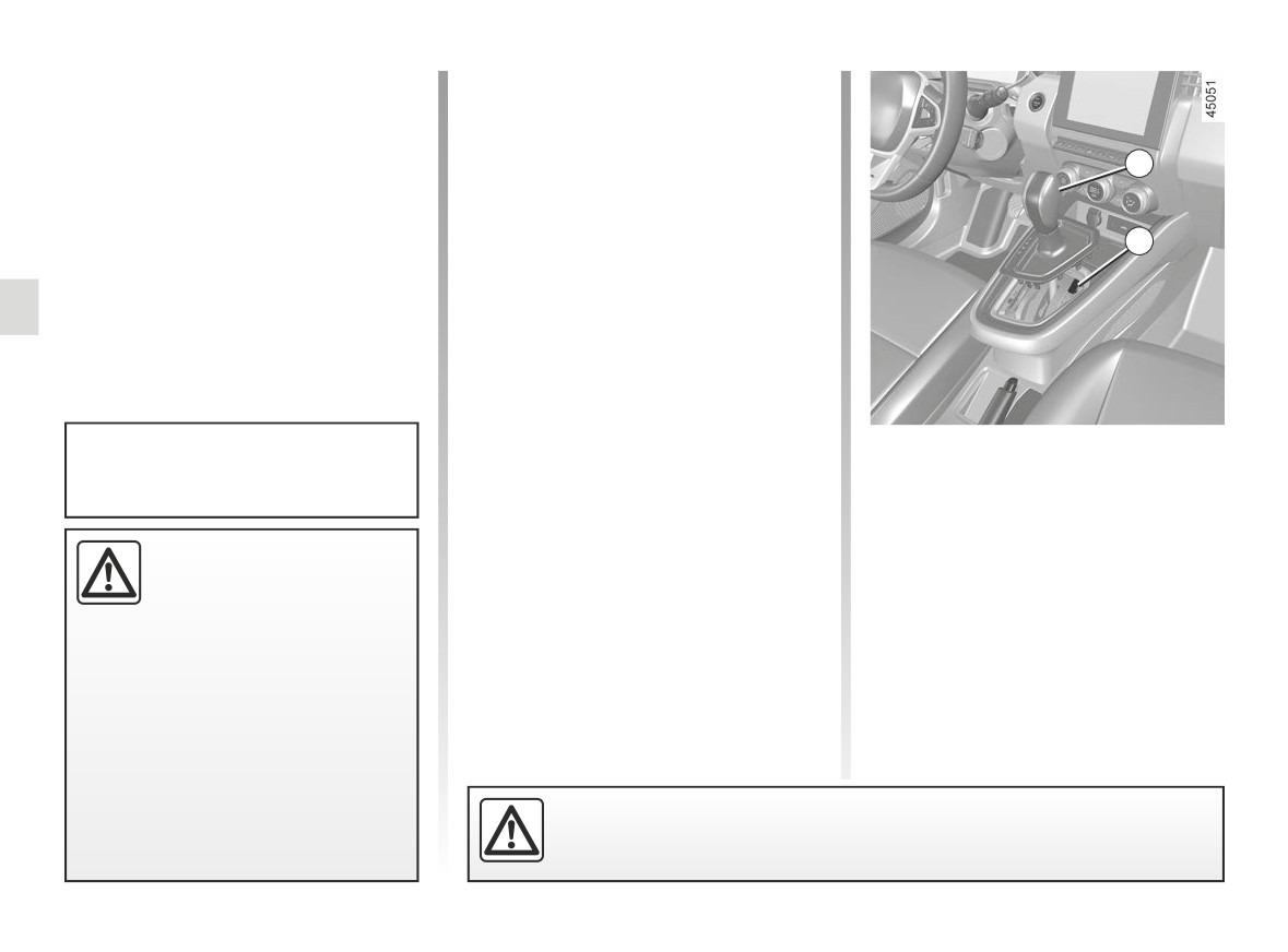
AUTOMATIC TRANSMISSION (4/4)
Parking the vehicle
Maintenance period
When the vehicle is stopped, move the
Refer to the maintenance document
lever to position P while keeping your
for your vehicle or consult an Approved
foot on the brake pedal: the gearbox is
Dealer to check whether the automatic
8
in neutral and the drive wheels are me-
gearbox requires scheduled mainte-
chanically locked by the driveshaft.
nance.
If it does not need to be serviced, there
Ensure that the electronic parking
is no need to top up the oil.
9
brake is engaged.
Operating faults
- when driving, if the message
“WARNING: Check Gearbox” ap-
pears on the instrument panel, it indi-
cates a failure.
Contact your approved Dealer as
When setting off, if the lever is stuck in
P position must only be engaged
soon as possible;
P when you press the brake pedal (e.g.
when the vehicle is stationary.
- when driving, if the message
battery fault), it is possible to manually
“WARNING: Gearbox Overheating”
release the lever to unblock the drive
appears on the instrument panel,
wheels. To do this, unclip the base of
An impact to the under-
stop as soon as possible to let the
the gaiter and press the 9 push button
side of the vehicle while
gearbox cool down and wait for the
while simultaneously pressing the 8
manoeuvring
(e.g. strik-
message to disappear;
button on the lever to unlock the lever
ing a post, raised kerb or
- troubleshooting on a vehicle with
and shift to position N.
other street furniture) may result in
an automatic gearbox ➥ 5.35.
Contact an authorised dealer as soon
damage to the vehicle (e.g. defor-
as possible.
mation of an axle).
To avoid any risk of accident, have
your vehicle checked by an ap-
proved Dealer.
For safety reasons, do not switch off the ignition before the vehicle has
come to a complete standstill.
2.148
CarManuals2.co
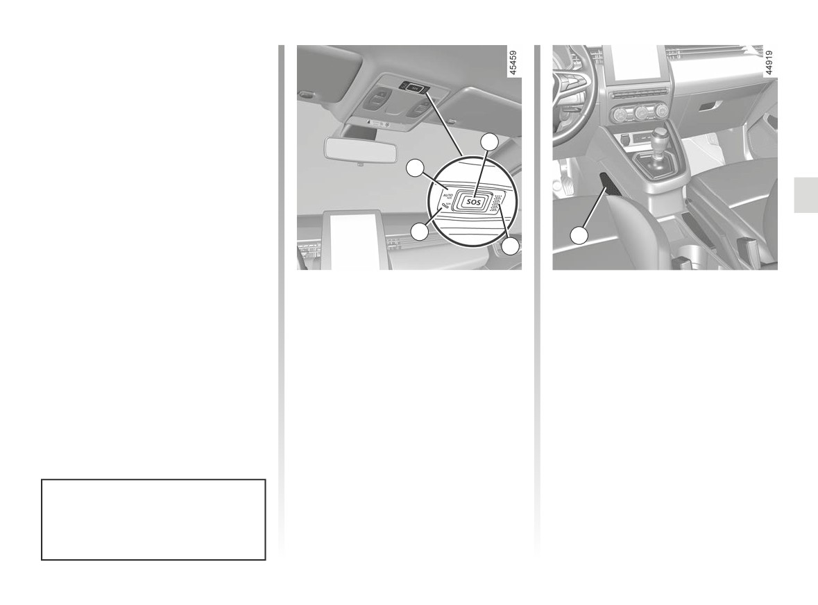
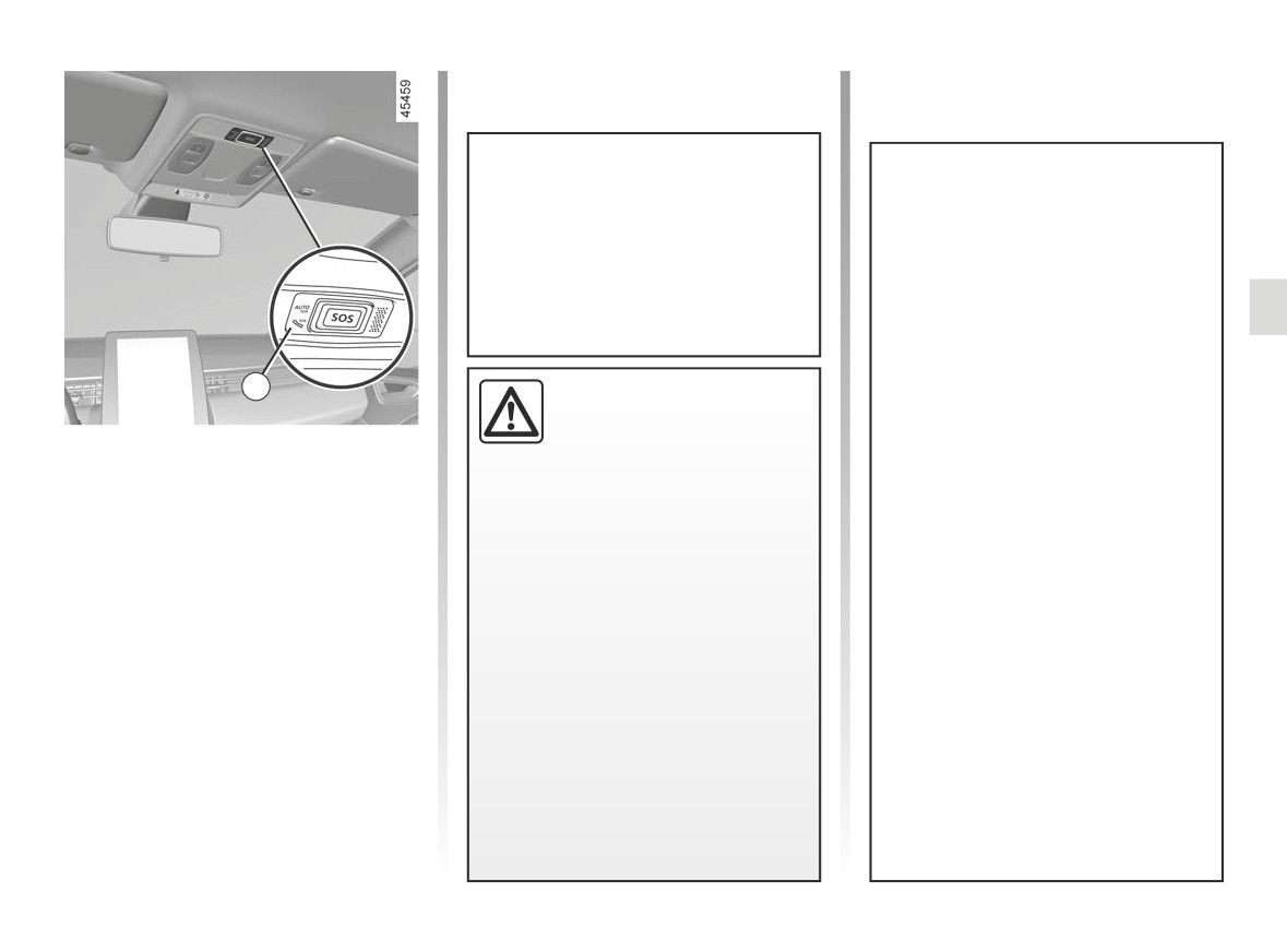
EMERGENCY CALL (1/3)
If the vehicle is equipped, the emer-
gency call function can be used to
call the emergency services (without
charge) automatically or manually in
the event of an accident or illness, re-
ducing the time it takes for the emer-
gency services to arrive.
3
Note: the emergency call operates:
2
– in countries covered by the associ-
ated telephone emergency services
and infrastructure compatible with
the system;
1
5
- depending on the network coverage
4
in the geographical region where the
vehicle is being driven.
1
System operation warning light:
A call is always made as follows:
If you use the emergency call function
– green: operational
to report an accident which you have
- the call is set up with the emergency
(network available);
witnessed, this implies stopping where
services;
- off: non-operational
traffic conditions allow in order for the
- send data related to the incident (ve-
(network unavailable);
emergency services to locate your ve-
hicle identification plate, local time
- red: operating
hicle and therefore the location of the
of the call, last positions, direction of
fault;
reported accident.
the vehicle) ;
- green flashing: call in progress.
In all cases, comply with local legisla-
- voice communication with the emer-
2
Automatic mode warning light.
tion.
gency services;
3
SOS button.
- if necessary, emergency assistance
4
Microphone.
is called.
5
Speaker.
Emergency call has two modes:
- automatic mode;
Use the emergency call only in the
event of an emergency you are in-
- Manual mode.
volved in, if you witness an accident
or if you feel ill.
2.149
CarManuals2.co
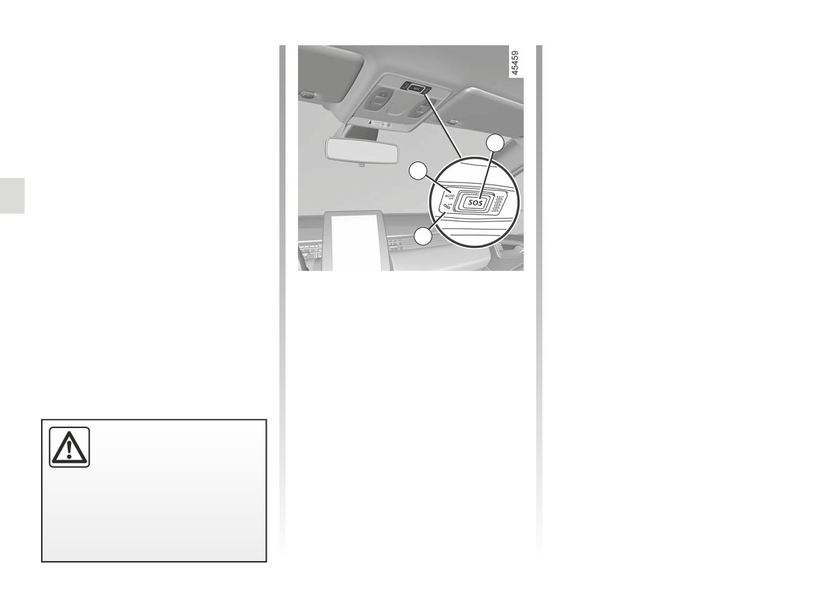
EMERGENCY CALL (2/3)
Automatic mode
In the event of unintended operation, it
is possible to cancel the call by press-
If the automatic mode 2 warning light
ing the 3 button for around two sec-
appears in green this confirms that the
onds, before the call is connected to
automatic system is activated.
the call centre.
The emergency call starts automati-
Once a call is established, only the call
cally in the event of an accident that
3
centre can end the call.
has required the activation of the pro-
tective equipment (seat belt pretension-
2
Test mode
ers, airbag etc.).
(depending on local laws)
Test mode is reserved exclusively for
Approved Dealers to check that the
emergency call feature is working prop-
1
erly.
To activate test mode:
Manual mode
- briefly press the 3 button three times;
The emergency call is carried out by:
- wait approximately 15 seconds;
- pressing and holding the 3 button for
- briefly press the 3 button three times.
at least three seconds;
Exit from test mode is automatic.
or
- pressing the
3 button five times
within ten seconds.
In the event of an acci-
dent, if the location and traf-
fic conditions permit, stay
close to the vehicle in order
to be able answer the call centre
quickly if necessary.
2.150
CarManuals2.co
EMERGENCY CALL (3/3)
The system operates with a dedi-
cated battery. The battery serv-
ice life is approximately four years
(the 1 warning light lights up in red
to warn you when approaching
expiry).
Without the emergency call feature,
Consult an approved dealer
the system is not trackable and will
not be under constant surveillance.
Data is automatically and constantly
erased, and the system stores only
1
To guarantee your safety
the last three positions of the vehi-
and the proper operation of
cle.
the system, any operation
Operating faults
carried out on the battery
According to legislation relevant to
In some cases, the emergency call may
(removal, disconnection, etc.) must
the country, data is only sent in the
not work (e.g. low battery).
be carried out by a qualified special-
event of an emergency call. Data
If the system detects an operating fault,
ist.
sent to the call centre is treated ac-
the 1 warning light illuminates in red for
cording to the personal data protec-
Risk of serious burns or electric
more than 30 minutes. Contact your ap-
tion laws applicable in the country
shocks.
proved Dealer as soon as possible;
where you are located. The system
You must respect the replacement
stores activity history data for
intervals (without exceeding them)
13 hours only.
as stated in the maintenance docu-
The vehicle owner has the right of
ment.
access to their data. They can re-
The battery is a specific type.
quest that the data be corrected,
Please ensure it is replaced with the
deleted or locked.
same type.
Call an approved Dealer.
2.151
CarManuals2.co
2.152
CarManuals2.co
Section 3: Your Comfort
MULTI-SENSE
3.2
Air Vents
3.4
Manual air conditioning, heating system
3.6
Automatic climate control
3.12
Air conditioning: information and advice on use
3.16
Air conditioning: information and advice on use
3.17
Multimedia equipment
3.18
Electric windows
3.20
Sun visor
3.23
Interior lighting
3.24
Passenger compartment storage, fittings
3.27
Accessories socket
3.32
Rear headrests
3.33
Rear bench seat: functions
3.34
Luggage compartment
3.35
Rear parcel shelf
3.36
Luggage compartment storage
3.37
Transporting objects in the luggage compartment
3.38
Transporting objects: towbar
3.39
Roof bars, spoiler
3.40
3.1
CarManuals2.co
MULTI-SENSE (1/2)
The “MULTI-SENSE” system enables
“Eco” mode
a choice between three driving modes
MULTI-SENSE
“Eco” mode focuses on energy saving.
that can be used to control driving,
The steering is smooth, engine and
ambient lighting, comfort and engine
gearbox management enable fuel con-
sound (depending on the vehicle):
sumption to be reduced ➥ 2.28.
– the “Eco” and “Sport” modes are
preconfigured and can be partially
customised (ambient lighting etc.) ;
- the “My Sense” mode is customis-
able.
The drive modes affect the:
- power-assisted steering;
- Electronic Stability Program;
- the response of the engine and gear-
Mode configuration
box.
They also affect the:
- the lighting in the passenger com-
partment and of the instrument
panel;
- information displayed on the multi-
media screen and, depending on the
mode selected, on the instrument
panel;
- depending on the vehicle, the engine
sound.
In all modes, it is possible to change
the colour of the ambient lighting
and to reset the settings to default.
The instrument panel style can be
modified only using
“My Sense”
Engine settings are specific to each
mode.
of the driving modes and cannot be
customised.
3.2
CarManuals2.co
MULTI-SENSE (2/2)
“Sport” mode
This mode enables an increased re-
1
sponsiveness from the engine and the
gearbox. The steering is firmer.
“My Sense” mode
Using standard default vehicle settings,
this mode can be used to manually con-
figure driving, ambient lighting, comfort
2
and engine sound (depending on the
vehicle).
Accessing the menu
You can access “MULTI-SENSE” (de-
pending on the vehicle):
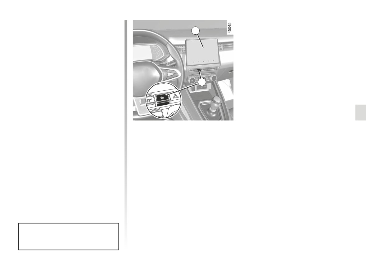
- from the multimedia screen 1;
- using the 2 switch.
Please refer to the multimedia instruc-
tions for further information.
After the engine is switched off, the
vehicle will always restart in “My
Sense” mode.
3.3
CarManuals2.co
AIR VENTS, air outlets (1/2)
3
4
5
6
2
1
7
8
7
1
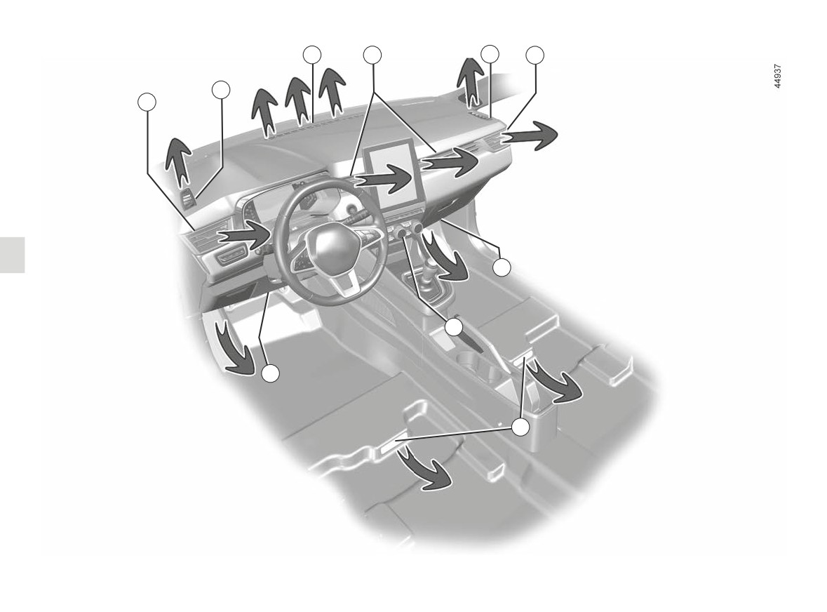
Left-hand air vent
9
6
Right-hand air vent
2 Left-hand side window demisting
7 Passenger footwell heater outlets
vent
8
Control panel
3
Windscreen demisting vents
9 Footwell heater outlets for rear
4
Centre air vents
passengers (depending on the
5 Right-hand side window demister
vehicle)
outlet
3.4
CarManuals2.co
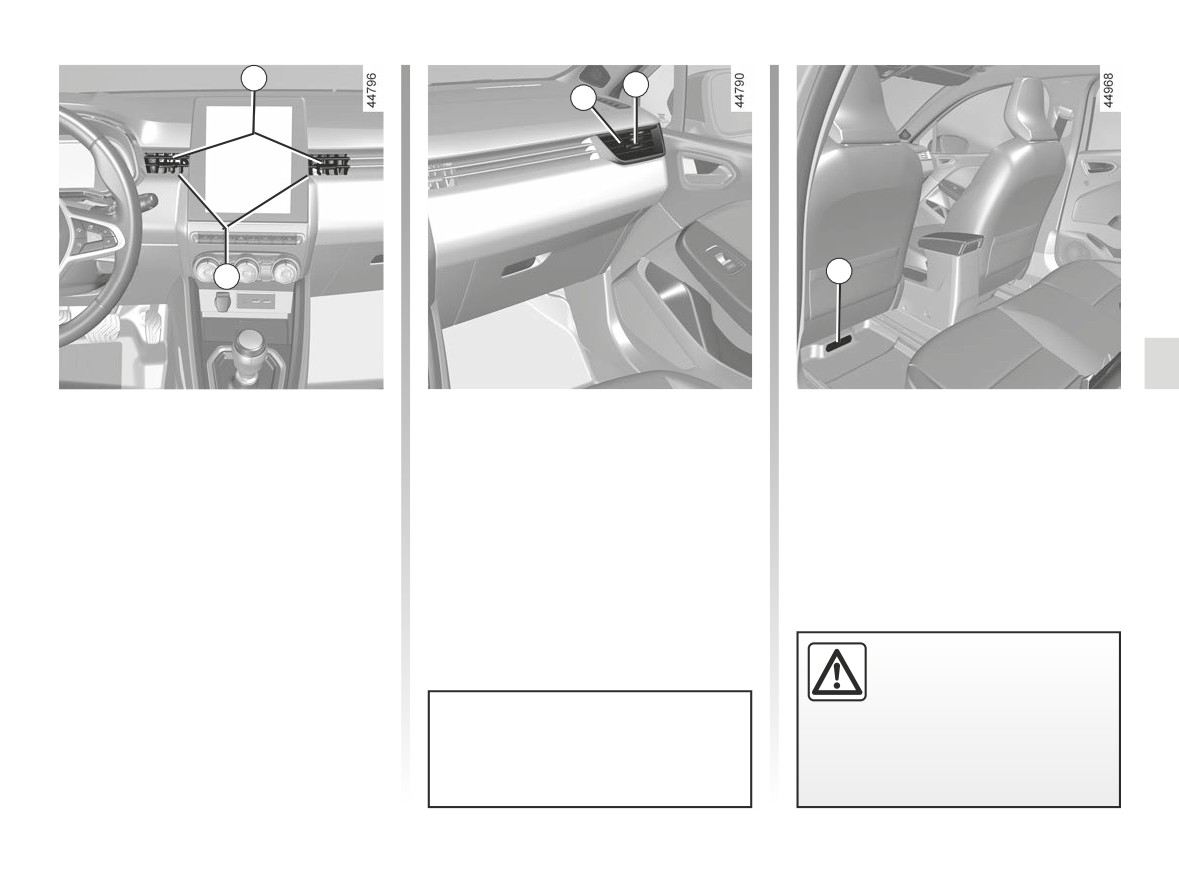
AIR VENTS, air outlets (2/2)
10
10
6
9
4
Centre 4 and side vents 1
Rear seats
and 6
(depending on vehicle)
Passenger footwell heater outlets 9.
Air flow
To close: move the cursor 10 towards
the outside of the vehicle beyond the
resistance point.
To open: move the cursor 10 towards
the inside of the vehicle.
Direction
Do not add anything to the
Move the cursor 10 to the desired po-
vehicle’s ventilation circuit
sition.
(for example, to remove
bad odours).
Do not attach any objects to the air
vents (e.g. telephone mounting).
There is a risk of damage or of
fire.
Risk of damage.
3.5
CarManuals2.co
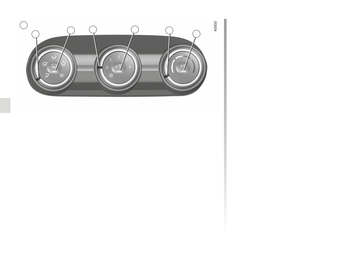
MANUAL AIR CONDITIONING, HEATING SYSTEM (1/6)
Distribution of air in the
A
2
3
4
5
passenger compartment
1
6
There are five air distribution options.
Turn control 1 to choose the distribution
option.
The air flow is directed to the
W
windscreen and the front side
window demisting vents.
The air flow is distributed be-
tween front side window de-
misting vents, the windscreen demist-
ing vents and the footwells.
The air flow is directed mainly
towards the footwells.
Controls A
The air flow is directed to-
(depending on vehicle)
wards the dashboard air vents,
1 Distribution of air in the passenger compartment.
the front footwells and, depending on
the vehicle, the second row footwells.
2 De-icing/demisting of the rear screen and, depending on the vehicle, the rear view
mirrors.
The air flow is mainly directed
J
to the dashboard air vents.
3 Adjusting the ventilation fan speed.
4 Air recirculation.
5 Adjusting the air temperature.
6 Air conditioning.
3.6
CarManuals2.co
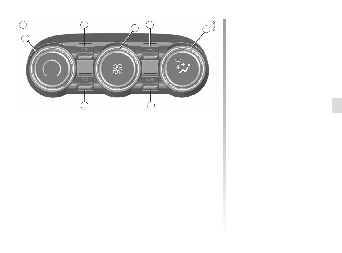
MANUAL AIR CONDITIONING, HEATING SYSTEM (2/6)
Switching air conditioning on
B
7
6
3
1
or off
5
Activation is not possible if the 3 control
is set to “0” (control A) or “OFF” (con-
trol B).
Press the 6 button to deactivate the air
conditioning. The button’s warning light
will go out.
The air conditioning system is used
for:
- lowering the temperature inside the
passenger compartment;
2
4
- eliminating condensation more
Controls B
quickly.
(depending on the vehicle)
1 Distribution of air in the passenger compartment.
2 De-icing/demisting of the rear screen and, depending on the vehicle, the rear view
mirrors.
3 Adjusting the ventilation fan speed.
4 Air recirculation.
5 Adjusting the air temperature.
6 Air conditioning control.
7 “Clear View” function.
3.7
CarManuals2.co
MANUAL AIR CONDITIONING, HEATING SYSTEM (3/6)
Air recirculation (isolation of
Stopping the system
Switching air conditioning on
the passenger compartment)
Turn the 3 control to “OFF” or “0” to
or off
switch off the system or press the 4
Air recirculation is for:
In automatic mode, the system switches
button. To start it, turn the 3 control to
the air conditioning system on or off,
- isolating the vehicle from the exter-
adjust the fan speed.
depending on the climate conditions.
nal atmosphere (driving in polluted
areas, etc.);
Activation is not possible if the 3 control
Clear View function
is set to “0” (control A) or “OFF” (con-
- to cool the passenger compartment
Press the 7 button: the integrated indi-
trol B).
temperature more quickly when air
conditioning is activated.
cator light comes on.
Press the 6 button to deactivate the air
conditioning. The button’s warning light
This function is managed automatically
This function quickly demists and de-
will go out.
but you can also activate it manually. In
ices the windscreen, the rear screen,
this case, the operation is confirmed by
the front side windows, and the door
The air conditioning system is used
the button’s warning light 4.
mirrors (depending on the vehicle). It
for:
automatically activates the air condi-
Manual use
tioning and rear screen de-icing func-
- lowering the temperature inside the
tions.
passenger compartment;
Press button 4, the button’s warning
light comes on.
Press button 2 to stop the heated rear
- eliminating condensation more
screen operating, and the integrated in-
quickly.
Prolonged use of this position may lead
dicator goes out.
to odours, caused by non-renewal of
air, and the formation of condensation
To exit this function, press button 7
on the windows. To avoid this, air recir-
or 5.
culation is disabled automatically after
a certain time.
Fuel consumption increases when
Using the demisting/de-icing func-
the air conditioning is being used
tion will disable the air recirculation.
(switch it off when it is not required).
3.8
CarManuals2.co
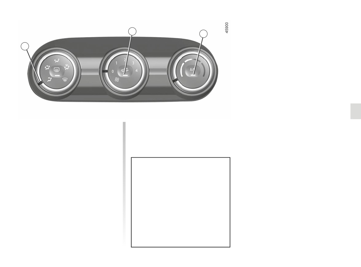
MANUAL AIR CONDITIONING, HEATING SYSTEM (4/6)
4
6
1
Switching the air
recirculation on
Press button 4: the button’s warning
light comes on. Under these conditions,
air is taken from the passenger com-
partment and is recirculated, with no air
being taken from outside the vehicle.
If the air conditioning is not acti-
Air recirculation is for:
vated (“A/C” warning light on the 6
button goes off), prolonged use of
- isolating the vehicle from the exter-
recirculated air may cause mist to
nal atmosphere (driving in polluted
form on the side windows and wind-
areas, etc.);
screen as well as other problems
- to cool the passenger compartment
due to the presence of non-recircu-
temperature more quickly when air
lated air in the passenger compart-
conditioning is activated.
ment. To avoid this, air recirculation
is disabled automatically after a cer-
tain time.
3.9
CarManuals2.co
MANUAL AIR CONDITIONING, HEATING SYSTEM (5/6)
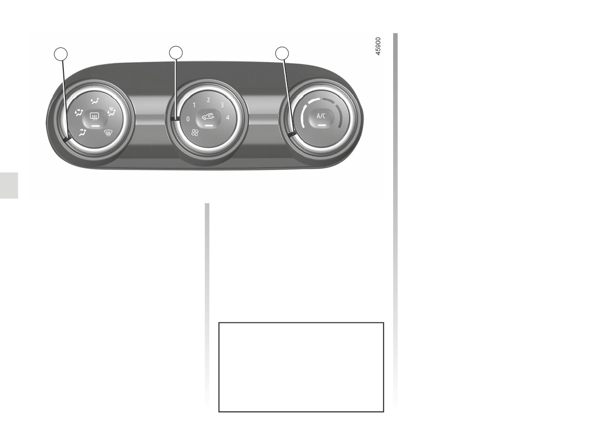
Adjusting the air temperature
1
3
5
Turn control 5 to obtain the desired
temperature. The further towards the
red the slide is, the higher the tempera-
ture will be.
When the air conditioning system is
used for long periods, it may begin to
feel cold. To increase the temperature,
turn control 5 to the right.
Adjusting the ventilation
speed
Move the 3 control to adjust the amount
of air blown. If you want to shut off the
flow of air, set the 3 control to “0” (con-
trol A) or “OFF” (control B).
The system is deactivated: the ventila-
tion speed is zero (vehicle stationary).
You can, however, still feel a slight flow
of air when the vehicle is moving.
Using W
position on the 1 con-
trol will disable the air recirculation
function in order to prevent misting
of the windscreen.
3.10
CarManuals2.co
MANUAL AIR CONDITIONING, HEATING SYSTEM (6/6)
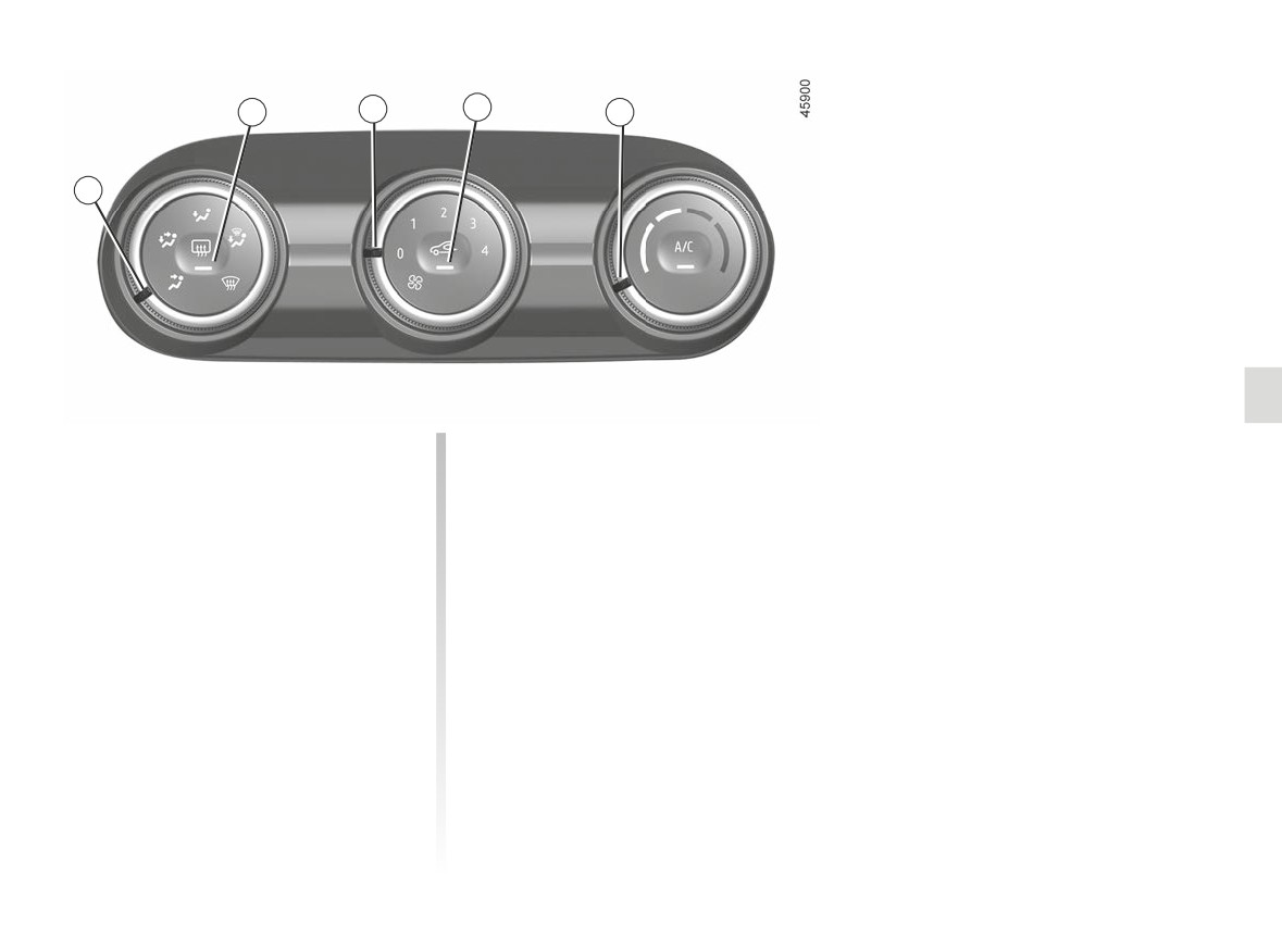
2
3
4
5
1
Rear screen de-icing/
Rapid demisting
demisting
Turn controls 1, 3 and 5 to:
With the engine running, press
- demisting W
;
button 2. The operating tell-tale comes
on.
- the fan speed in position 3 or 4;
This function permits rapid demisting/
- maximum temperature.
de-icing of the rear screen and de-icing
Press the 4 button to deactivate the air
of the door mirrors (on equipped vehi-
recirculation (warning light off).
cles).
To exit this function, press button 2
again. Warning light goes out.
Demisting automatically stops.
3.11
CarManuals2.co
AUTOMATIC CLIMATE CONTROL (1/4)
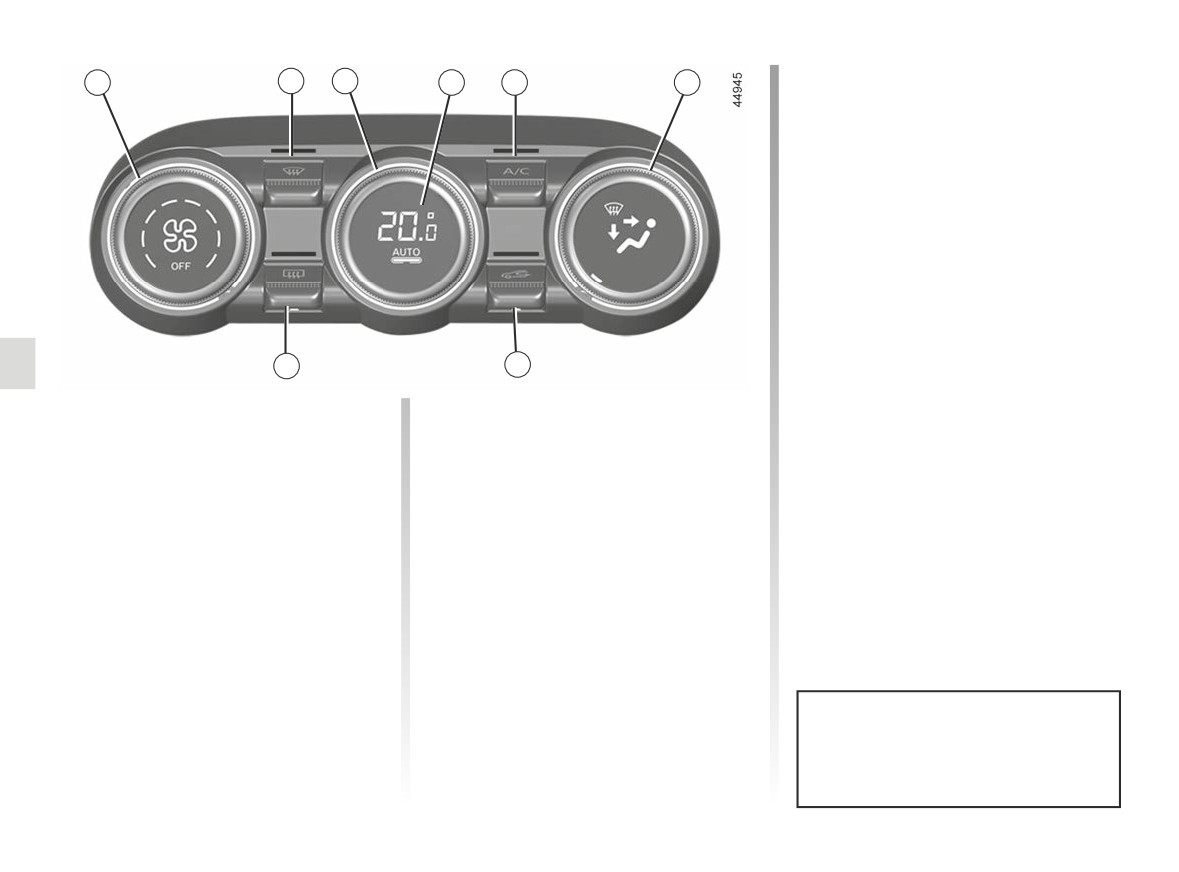
Adjusting the ventilation
1
2
3
4
5
6
speed.
In automatic mode, the system uses
the most suitable amount of air to reach
and maintain the desired comfort level.
You can still adjust the ventilation
speed by turning control 1 to increase
or reduce the ventilation speed.
Adjusting the air temperature
Turn control 3 to obtain the desired
temperature.
8
7
Turning the control to the
right
in-
creases the temperature.
The controls
Automatic mode
(depending on the vehicle)
The automatic climate control system
guarantees comfort in the passen-
1
Adjusting the ventilation fan speed.
ger compartment and good visibility
2
“Clear View” function.
(except in the event of extreme condi-
3
Adjusting the air temperature.
tions), while optimising consumption.
The system controls the ventilation
4
Automatic mode.
speed, air distribution, air recirculation,
5
Air conditioning control.
and starting and stopping the air condi-
tioning and air temperature.
6
Distribution of air in the passenger
compartment.
AUTO: allows the selected comfort
level to be best attained, depending on
7
Air recirculation.
the exterior conditions. Press button 4.
8
De-icing/demisting of the rear screen
and, depending on the vehicle, the
Any action on a button other than
rear view mirrors.
the AUTO button triggers deactiva-
tion of automatic mode.
3.12
CarManuals2.co
AUTOMATIC CLIMATE CONTROL (2/4)
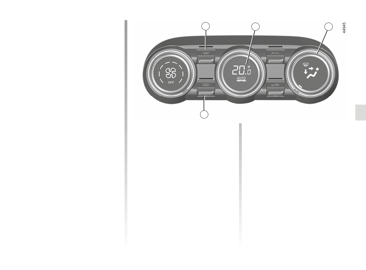
Clear View function
2
4
6
Press the 2 button: the integrated indi-
cator light comes on.
This function quickly demists and de-
ices the windscreen, the rear screen,
the front side windows, and the door
mirrors (depending on the vehicle). It
automatically activates the air condi-
tioning and rear screen de-icing func-
tions.
Press button 8 to stop the heated rear
screen operating, and the integrated in-
dicator goes out.
8
To exit this function, press button 2
or 4.
Adjusting the distribution
The air flow is directed towards
the dashboard air vents, the
of air in the passenger
front footwells and, depending on the
compartment
vehicle, the second row footwells.
Turn control 6. The integrated warning
The air flow is mainly directed
light in the button comes on.
to the dashboard air vents.
All the air is then directed to
W
the windscreen and front side
owards the footwells.
window demisting vents.
The air flow is distributed be-
tween front side window de-
misting vents, the windscreen demist-
ing vents and the footwells.
3.13
CarManuals2.co
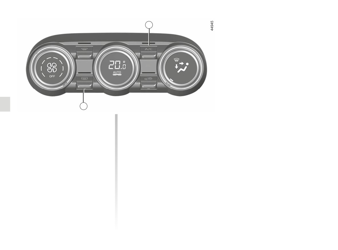
AUTOMATIC CLIMATE CONTROL (3/4)
5
8
Rear screen de-icing/
Switching air conditioning on
demisting
or off
Press the 8 button: the integrated in-
In automatic mode, the system switches
dicator light comes on. This function
the air conditioning system on or off,
enables rapid demisting or de-icing of
depending on the climate conditions.
the rear screen and de-icing of the rear
Press the 5 button to deactivate the air
view mirrors (on equipped vehicles).
conditioning. The integrated indicator
To exit this function, press button 8
light goes off.
again. Demisting automatically stops.
3.14
CarManuals2.co
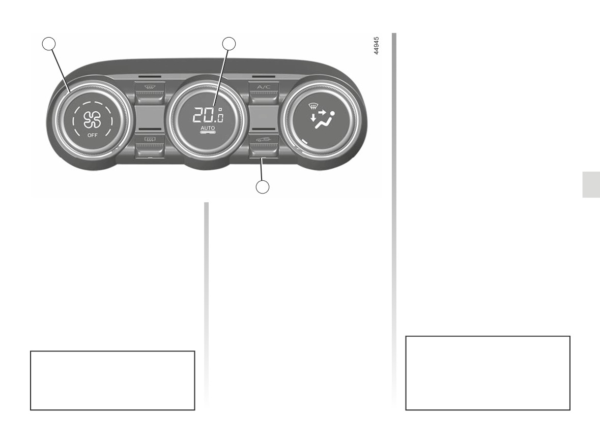
AUTOMATIC CLIMATE CONTROL (4/4)
Stopping the system
1
4
Turn the control 1 to “OFF” to stop the
system. To start it, turn the control 1
again, then adjust the fan speed or
press the button 4.
7
Air recirculation (isolation of
Manual use
the passenger compartment)
Press the 7 button: the integrated indi-
cator light comes on.
This function is managed automatically
but you can also activate it manually. In
Prolonged use of this position may lead
this case, the operation is confirmed by
to odours, caused by non-renewal of
a warning light on the button 7.
air, and the formation of condensation
on the windows.
To avoid this, air recirculation is disa-
bled automatically after a certain time.
Fuel consumption increases when
Using the demisting/de-icing func-
the air conditioning is being used
tion will disable the air recirculation.
(switch it off when it is not required).
3.15
CarManuals2.co
AIR CONDITIONING: information and operating instructions (1/2)
Advice on use
Fuel consumption
Operating faults
In some situations (air conditioning off,
You will normally notice an increase in
As a general rule, contact your ap-
air recirculation activated, ventilation
fuel consumption (especially in town)
proved dealer in the event of an oper-
speed at zero or low etc.), you may
when the air conditioning is operating.
ating fault.
notice that condensation starts to form
For vehicles fitted with air conditioning
- Reduction in de-icing, demisting
on the windows and windscreen.
with no automatic mode, switch off the
or air conditioning performance.
If there is condensation, use the “Clear
system when it is not required.
This may be caused by the passen-
View” function to remove it, then use
ger compartment filter cartridge be-
Advice for reducing consumption
the air conditioning in automatic mode
coming clogged.
and helping to preserve the environ-
to stop it forming again.
ment
- No cold air is being produced.
Check that the controls are set cor-
Drive with the air vents open and the
rectly and that the fuses are sound.
windows closed. If the vehicle has been
Otherwise, switch off the system.
parked in the sun, open the doors for a
few moments to let the hot air escape
before starting the engine.
Presence of water under the
vehicle
Maintenance
After prolonged use of the air condi-
Refer to the Maintenance Document
tioning system, it is normal for water
for your vehicle for the inspection fre-
to be present under the vehicle. This is
quency.
caused by condensation.
Do not add anything to the
vehicle’s ventilation circuit
Do not open the refriger-
(for example, to remove
Use the air conditioning system reg-
ant fluid circuit. The fluid
bad odours).
ularly, even in cold weather, running
may damage eyes or skin.
There is a risk of damage or of
it at least once a month for approxi-
fire.
mately 5 minutes.
3.16
CarManuals2.co
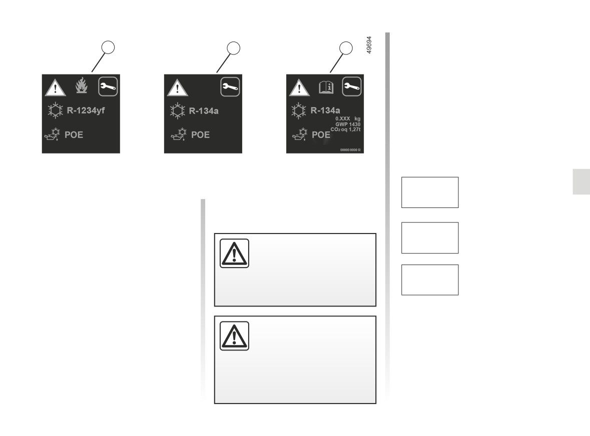
AIR CONDITIONING: information and operating instructions (2/2)
Type of refrigerant fluid
Ñ
A
A
A
Type of oil in the air condi-
tioning circuit
Inflammable product
Consult the driver’s hand-
book
Maintenance
Quantity of refrigerant
x.xxx kg
fluid present in the ve-
The refrigerant fluid circuit (of which
hicle.
some components are hermetically
sealed) may contain fluorinated green-
Global
Warming
house gases.
Potential
GWP xxxxx
(CO2 equi-
Do not open the refriger-
Depending on the vehicle, you will find
valent).
ant circuit. The fluid may
the following information on label A af-
damage eyes or skin.
fixed inside the engine compartment.
CO2 eq
Quantity in weight and
The presence and location of the infor-
x.xx t
in CO2 equivalent.
mation on label A depends on the ve-
hicle.
Before carrying out any
action in the engine com-
partment, you must switch
off the ignition.
➥ 2.4 or
➥ 2.6.
3.17
CarManuals2.co
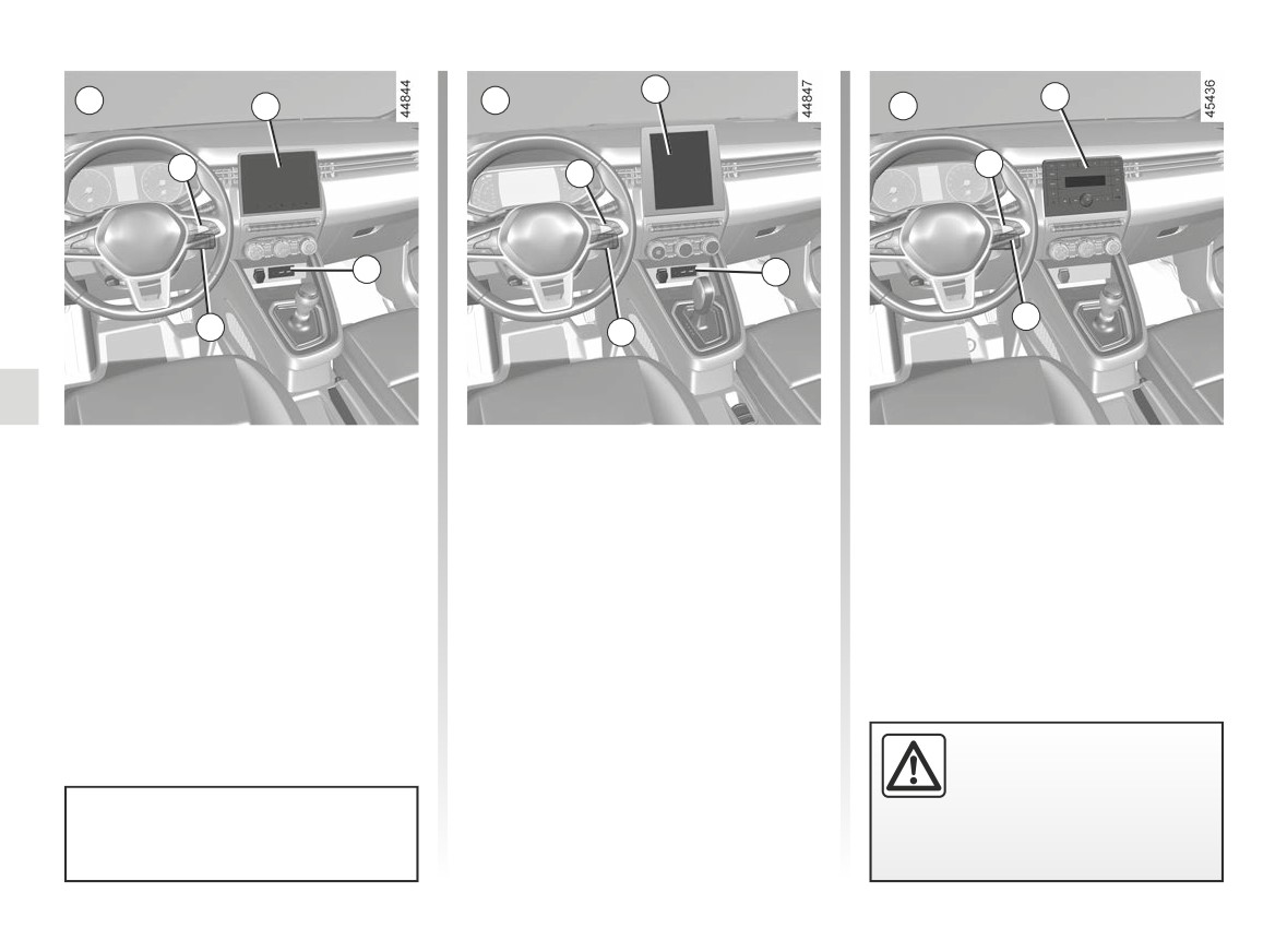
MULTIMEDIA EQUIPMENT (1/2)
1
A
B
5
1
C
4
4
4
2
2
3
3
3
Multimedia systems A, B or
Multimedia sockets 2
The sockets USB can also be used to
recharge accessories with a maximum
radio C
You can use the USB sockets to access
power rating of 12 Watts (5 Volts) per
The location and operation of equip-
the multimedia content of your acces-
socket, which have been approved by
ment may vary according to the vehicle.
sories and to update the system.
our Technical Department.
1 Multimedia screen.
The various sources can be selected
The JACK socket enables the radio to
2 Multimedia sockets.
using the multimedia screen or the
be used with an auxiliary cable.
3 Steering column controls.
radio and the steering column controls.
4 Steering wheel controls.
5 Radio.
Connect accessories with a
maximum power of 12 watts
only.
Please refer to the multimedia in-
Fire hazard.
structions for further information.
3.18
CarManuals2.co
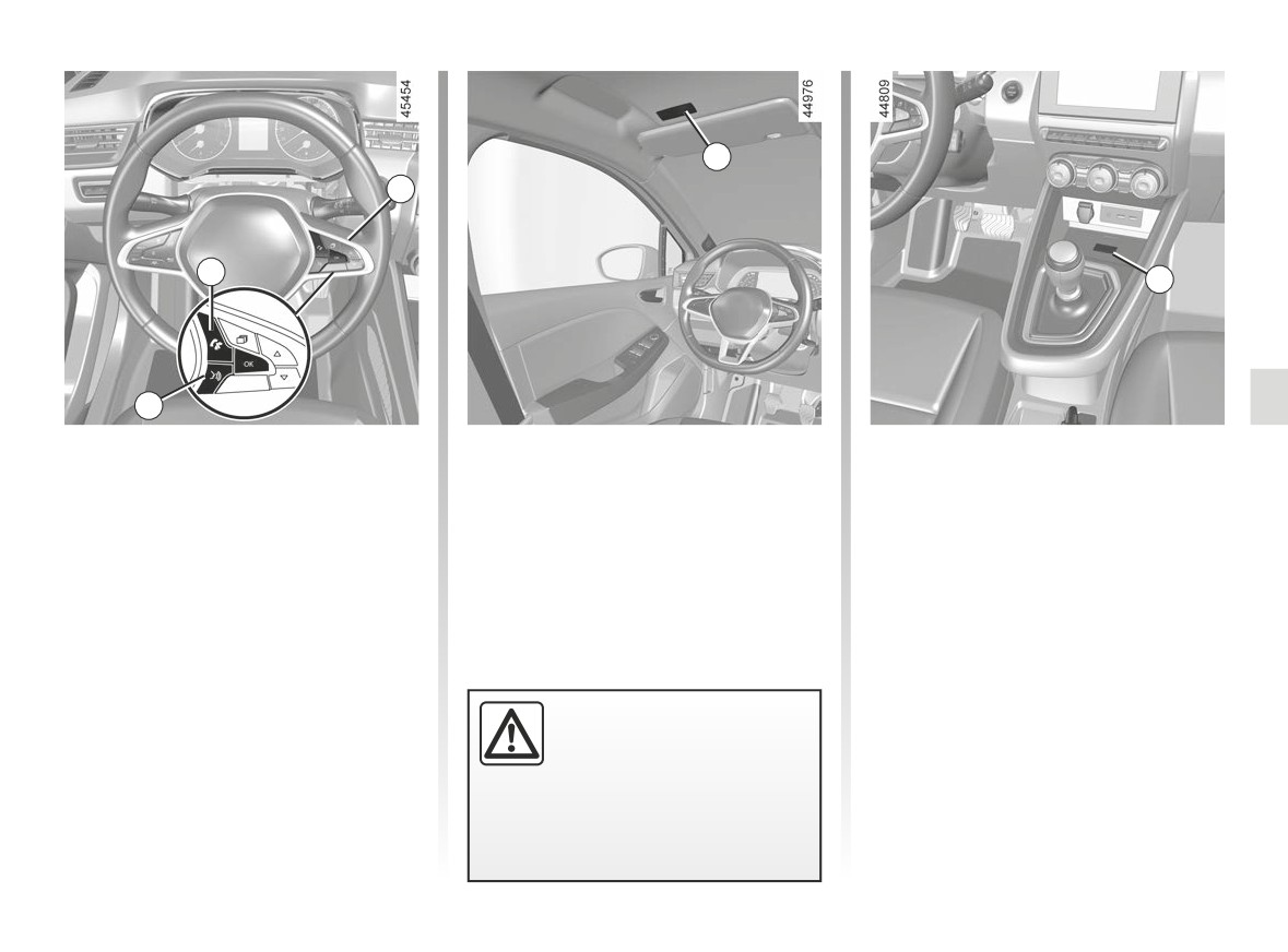
MULTIMEDIA EQUIPMENT (2/2)
8
4
6
9
7
Steering column controls 4
Microphone 8
Wireless charger 9
You can use the hands-free telephone 6
➥ 3.27
and voice recognition 7 controls on ve-
hicles fitted with these.
Using the telephone
We remind you of the need
to conform to the legislation
in force concerning the use
of such equipment.
3.19
CarManuals2.co