Renault Clio (2023 year). Manual in english - page 5
DRIVING CORRECTION DEVICES AND AIDS (3/5)
Electronic stability program
Understeer control
In some situations (driving on very wet
ground: snow, mud, etc. or driving with
(ESC) with understeer control
This system optimises the action of the
snow chains fitted), the system may
and traction control
ESC in the case of pronounced unders-
reduce the engine output to limit wheel-
teering (loss of front axle road holding).
spin.
Electronic stability program ESC
Traction control
This system helps you to keep control
Operating faults
of the vehicle in critical driving condi-
This system helps to limit wheelspin of
When the system detects an operat-
tions (avoiding an obstacle, loss of grip
the drive wheels and to control the ve-
ing fault the message “Check ESC” and
on a bend, etc.).
hicle when pulling away accelerating or
decelerating.
appear
Operating principle
Operating principle
on the instrument panel. In this case,
A sensor in the steering wheel detects
the ESC and traction control system
Using the wheel sensors, the system
the direction selected by the driver.
are deactivated.
measures and compares the speed of
Other sensors throughout the vehicle
the drive wheels at all times and slows
Consult an approved dealer.
measure the actual direction.
down their over-rotation. If a wheel is
starting to slip, the system brakes au-
The system compares driver input to
tomatically until the drive supplied be-
the actual trajectory of the vehicle and
comes compatible with the level of grip
corrects the trajectory if necessary by
under the wheel again.
controlling the braking of certain wheels
and/or engine power. In the event that
The system also adjusts the engine
speed to the grip available under the
the system is triggered, the
wheels, independently of the pressure
warning light flashes on the instrument
exerted on the accelerator pedal.
panel.
2.46
CarManuals2.co
DRIVING CORRECTION DEVICES AND AIDS (4/5)
Emergency brake assist
Braking anticipation
This system supplements the ABS
Depending on the vehicle, when you
and helps reduce vehicle stopping dis-
rapidly release the accelerator, the
tances.
system anticipates the braking ma-
noeuvre in order to reduce stopping
Operating principle
distances.
The system is for detecting an emer-
Special cases
gency braking situation. In this case,
the braking system immediately devel-
When using the cruise control:
ops maximum power and may trigger
- if you use the accelerator, when you
ABS regulation.
release it, the system may be trig-
ABS braking is maintained as long as
gered;
the brake pedal is applied.
- if you do not use the accelerator, the
These functions are an ad-
system will not be triggered.
ditional aid in the event of
Brake lights come on
critical driving conditions,
Depending on the vehicle, these may
Operating faults
enabling the vehicle behav-
flash in the event of sudden decelera-
When the system detects an operating
iour to be adapted to suit the driving
tion.
fault the message “WARNING: Check
conditions.
Braking System” appears on the instru-
These functions do not take the
place of the driver. They do not
ing light.
increase the vehicle’s limits and
Consult an approved dealer.
should not encourage you to
drive more quickly. Therefore,
they can under no circumstances
replace the vigilance or responsibil-
ity of the driver when manoeuvring
the vehicle (the driver must always
be ready for sudden incidents which
may occur when driving).
2.47
CarManuals2.co
DRIVING CORRECTION DEVICES AND AIDS (5/5)
Hill start assistance
The hill start assistance
Depending on the gradient of the in-
system cannot completely
cline, this system assists the driver
prevent the vehicle from
when starting on a hill. It prevents the
rolling backwards in all sit-
vehicle from rolling backwards by au-
uations (extremely steep gradients
tomatically applying the brakes when
etc.).
the driver lifts his/her foot off the brake
In all cases, the driver may depress
pedal to depress the accelerator pedal.
the brake pedal to prevent the vehi-
cle from rolling backwards.
System operation
The hill start assistance function
It only operates when the gear lever is
should not be used for prolonged
in a position other than neutral (other
stops: use the brake pedal.
than N or P for automatic transmis-
sions) and the vehicle is completely
This function is not designed to im-
stationary (brake pedal depressed)
mobilise the vehicle permanently.
The system holds the vehicle for ap-
If necessary, use the brake pedal to
proximately 2 seconds. The brakes are
stop the vehicle.
then gradually released (the vehicle will
The driver must remain particularly
move according to the slope).
vigilant when driving on slippery or
low-grip surfaces.
Risk of serious injury.
2.48
CarManuals2.co
LANE DEPARTURE WARNING (1/5)
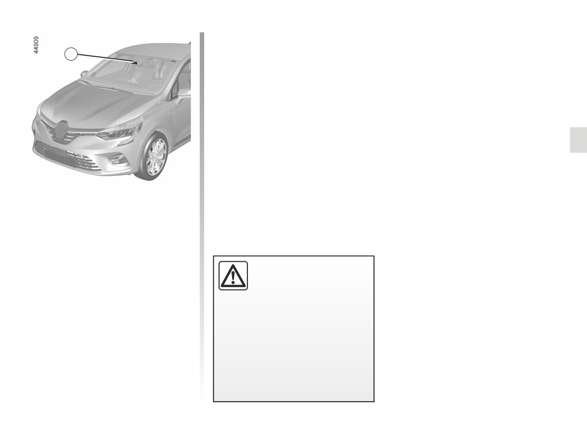
Location of the camera 1
Make sure the windscreen is not ob-
1
scured (dirt, mud, snow, condensation
etc.).
Using information from the 1 camera,
the function warns the driver when a
continuous or broken line is crossed
or when approaching the roadside (di-
vider, barrier, pavement, embankment,
etc.) without the direction indicator
lights being activated.
This function is an addi-
tional driving aid. This func-
tion is not under any cir-
cumstances intended to
replace the due care and attention
of the driver, who should at all times
be in control of the vehicle.
The lane departure warning func-
tion does not correct the vehi-
cle’s trajectory.
2.49
CarManuals2.co
LANE DEPARTURE WARNING (2/5)
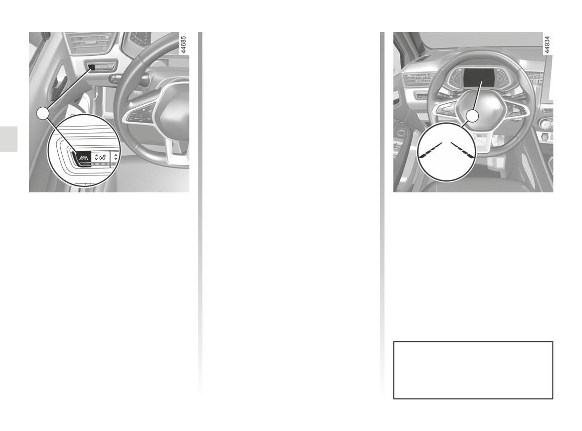
To disable the function, press the 2
switch as many times as required to
select
“Lane departure warning off”
(or, depending on the vehicle “Lane
Keeping deactivated”) on the instru-
goes
ment panel. Warning light
out on the instrument panel.
2
3
Operation
When the function is activated, the
warning light and the left and
right lines 3 are displayed in grey on the
instrument panel.
The function is set to notify the
Activation/deactivation
The function alerts the driver:
driver if:
- by a vibration in the steering wheel;
To activate the function, press the 2
- speed is between approximately
and
switch as many times as required to
43 mph (70 km/h) and 112 mph
select “Lane Departure Warning” on
(180 km/h);
- the
warning light and 3 the in-
the instrument panel. The “Lane depar-
and
dicator for the crossed line turn red.
ture warning on” message and “”
- the
warning light and left/right
warning light are displayed on the in-
line indicators 3 are coloured white.
strument panel.
The warning function is triggered
if the vehicle breaches a line or ap-
proaches a roadside (divider, barrier,
pavement, embankment, etc.) without
the direction indicator lights being ac-
tivated.
Each time the vehicle is started,
the function continues the mode
saved the last time the engine was
stopped.
2.50
CarManuals2.co
LANE DEPARTURE WARNING (3/5)
Temporarily not available
Conditions for non-activation
4
- Very fast lane departure;
of the system
The system cannot be activated when:
- driving continuously on a line;
- four seconds approximately after
- reverse gear is engaged;
changing lanes;
- the field of vision of the camera is ob-
- tight bends;
structed;
- impaired visibility;
- the û
warning light is displayed.
- activation of one of the direction indi-
cator lights;
The
warning light and the left/
right line indicators turn to grey on the
- strong acceleration;
instrument panel.
- ...
When the function is not available, the
Adjustment
-
“Alert”: adjust the line detection sen-
warning light and the left/right in-
sitivity level. To do this, select:
Vehicles fitted with a multimedia
dicators turn to grey on the instrument
screen.
- “Late”: line detected when cross-
panel.
ing;
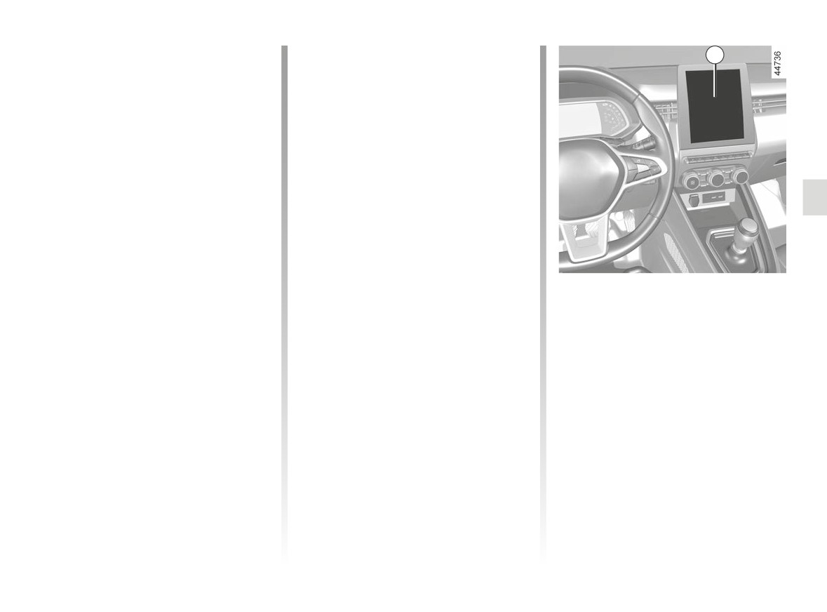
To access the function settings from the
multimedia screen 4 please refer to the
- “Standard”: line detected on ap-
multimedia instructions:
proach;
- “Vibration”: adjust the steering wheel
- “Early”: line detected nearby.
vibration level;
2.51
CarManuals2.co
LANE DEPARTURE WARNING (4/5)
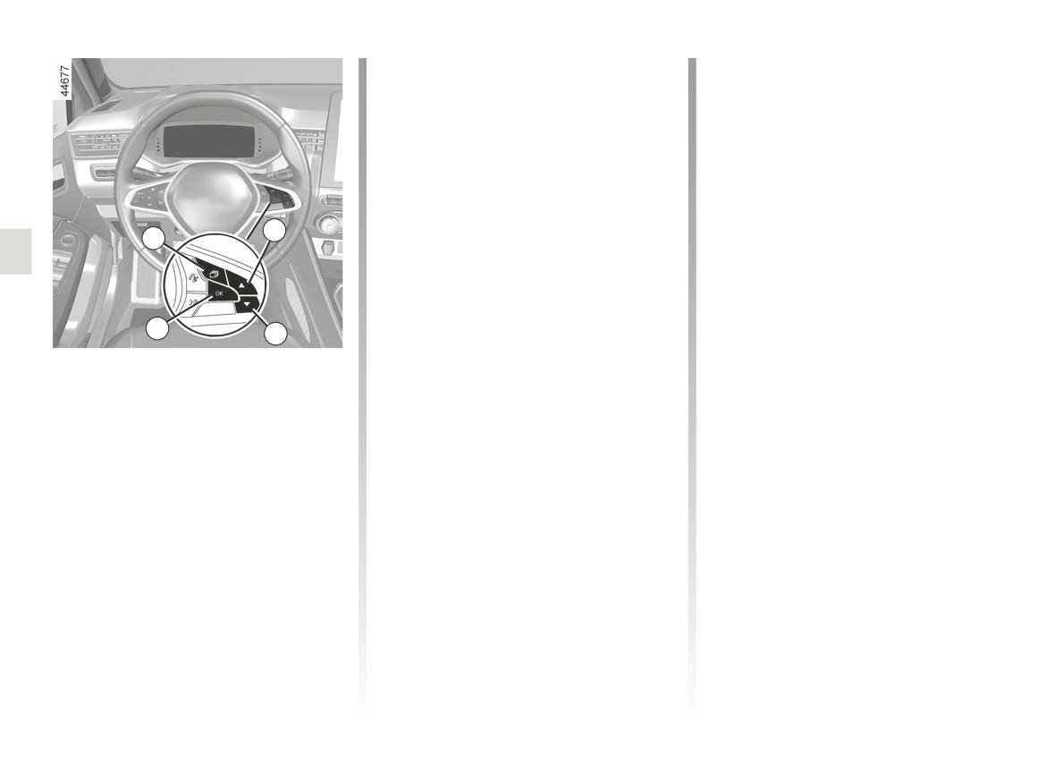
-
press the 6 or 7 control repeatedly to
Operating faults
reach the “DRIVING ASSIST” menu.
In the event of a malfunction, the left
Press the switch 8 OK;
and right line indicators (and, depend-
-
repeatedly press the 6 or 7 control
to access the “Lane departure warn-
ing on display style, the
warning
ing” or “Lane Departure Sensitivity”
light) disappear or stay grey on the in-
menu. Press the switch 8 OK;
strument panel.
-
scroll repeatedly pressing control 6
In some cases, they are accompa-
6
or 7 to adjust the setting. Press the 8
nied by the message “Front camera to
5
OK button.
check” or the
warning light on
the instrument panel.
Consult an approved dealer.
8
7
Adjustments (continued)
Vehicles not fitted with a multimedia
screen
- With the vehicle stopped, press the
switch 5 as many times as required
to reach the “Vehicle” tab;
- press the 6 or 7 control repeatedly to
reach the “Settings” menu. Press the
switch 8 OK;
2.52
CarManuals2.co
LANE DEPARTURE WARNING (5/5)
This function is an additional driving aid. This function is not under any circumstances intended to replace the due care
and attention of the driver, who should at all times be in control of the vehicle.
System servicing/repairs
- In the event of an impact, the camera alignment may be changed, and its operation may consequently be affected. Deactivate
the function, then consult an authorised dealer.
- Any work in the area where the camera is located (repairs, replacements, windscreen modifications etc.) must be carried
out by a qualified professional.
Only an authorised dealer is qualified to service the system.
In the event of system disturbance
Some conditions can disturb or damage the operation of the system, such as:
- windscreen obscured (by dirt, ice, snow, condensation etc.);
- a complex environment (tunnel etc.);
- poor weather conditions (snow, rain, hail, black ice etc.) ;
- poor visibility (night, fog etc.);
- the road markings are irregular or difficult to distinguish (e.g. partially erased, excessive spacing, distorted road surface) ;
- being dazzled (glaring sun, lights of vehicles travelling in the opposite direction etc.);
- the road is narrow, winding or undulating (tight bends etc.);
- closely following a vehicle travelling in the same lane.
Risk of false alarms or absence of warnings
2.53
CarManuals2.co
LANE KEEPING ASSIST (1/6)
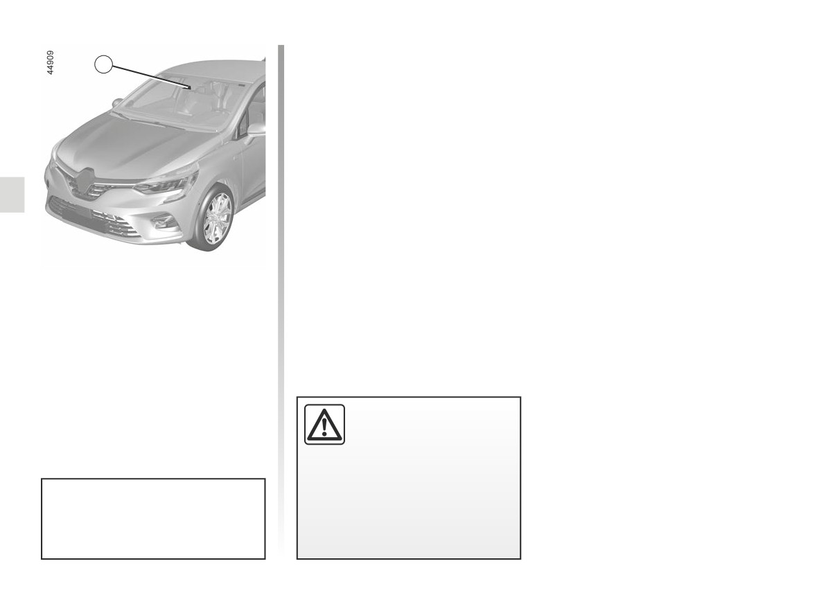
Location of the camera 1
1
Make sure the windscreen is not ob-
scured (dirt, mud, snow, condensation
etc.).
Using information from the 1 camera,
the function triggers corrective action
on the vehicle steering system when
a continuous or broken line is crossed
or when approaching the roadside (di-
vider, barrier, pavement, embankment,
etc.) without the direction indicator
lights being activated.
This function is an addi-
tional driving aid. This func-
tion is not under any circum-
stances intended to replace
the due care and attention of the
driver, who should at all times be
in control of the vehicle.
You can retake control of the ve-
hicle at any time by operating the
steering wheel.
2.54
CarManuals2.co
LANE KEEPING ASSIST (2/6)
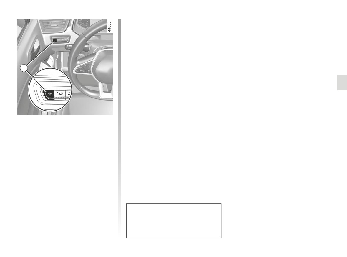
To disable the function, press the 2
switch as many times as required to
select “Lane Keeping deactivated” on
the instrument panel.
goes out on the in-
Warning light
strument panel.
2
Note: deactivating the “Lane Keeping
Assist” function causes deactivation of
the “Lane Departure Warning” function.
Activation/deactivation
To activate the function, press the 2
switch as many times as required to
select “Lane Keeping Assist” on the in-
strument panel.
The “Lane Keeping activated” message
and “
” warning light are displayed
on the instrument panel.
When Lane Keeping Assist is activated,
the “Lane Departure Warning” function
is automatically activated.
➥ 2.49.
Each time the vehicle is started,
the function continues the mode
saved the last time the engine was
stopped.
2.55
CarManuals2.co
LANE KEEPING ASSIST (3/6)
In these cases:
Special cases
- the function triggers an action on the
When using the function:
vehicle’s steering system to correct
-
If the system can no longer detect
the vehicle trajectory;
any action by the driver on the steer-
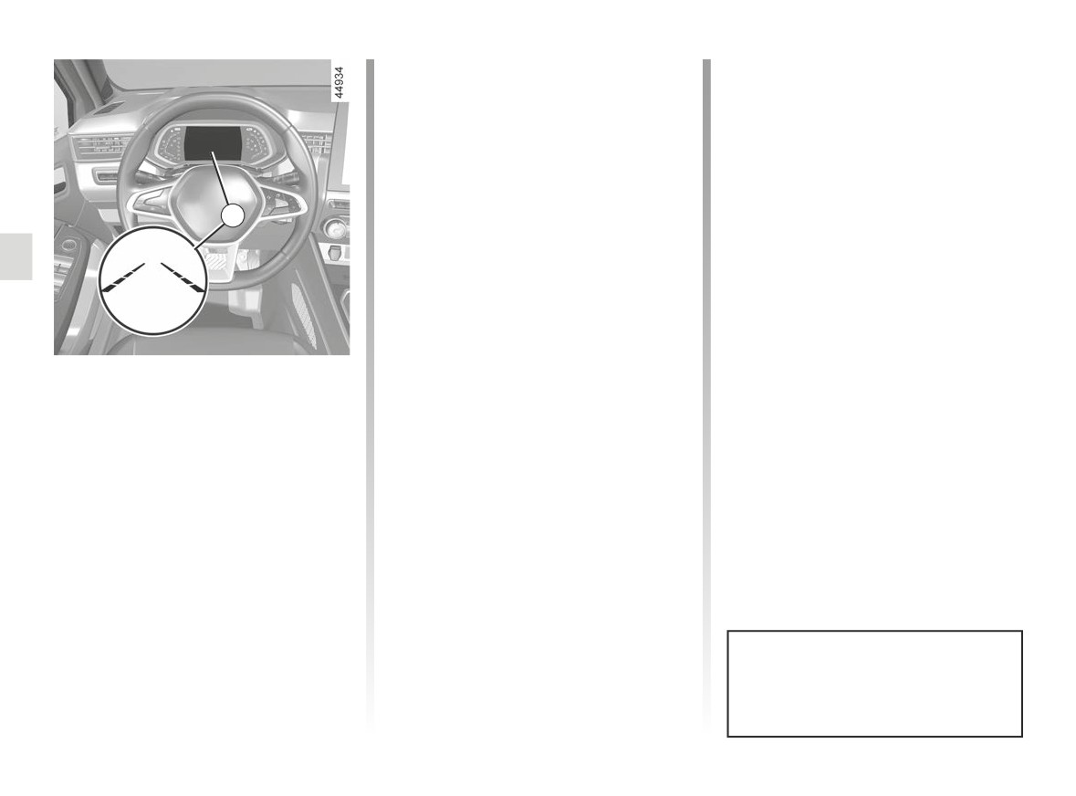
- the 3 indicator on the side of the
ing wheel, the
warning light
breached line turns to yellow on the
appears in orange on the instrument
instrument panel.
panel, accompanied by the message
3
Note: on bends, the function allows for
“Keeping hands on steering wheel”
slightly cutting the bend.
and an audible warning.
If the corrective action on the steer-
The audible warning is emitted along
with the warning light and message
ing system is not sufficient, the
until the driver takes control;
warning light and 3 indicator on the side
of the breached line turn to red on the
-
if the system is active for too long,
instrument panel, accompanied by a vi-
an audible warning is emitted and
Operation
bration on the steering wheel.
the indicator 3 on the side of the line
When the function is activated, the
concerned flashes until the driver
takes control.
warning light and the left and
right lines 3 are displayed in grey on the
instrument panel.
The function is set to operate when
the vehicle speed is between approxi-
mately 43 mph (70 km/h) and 112 mph
(180 km/h) and if the
warning
light and left-hand and right-hand line
indicators 3 appear in white.
The function operates if the vehicle
breaches a line or if the vehicle ap-
proaches the roadside (divider, barrier,
You can interrupt the trajectory cor-
pavement, embankment, etc.) without
rection at any time by moving the
the direction indicator lights being ac-
steering wheel.
tivated.
2.56
CarManuals2.co
LANE KEEPING ASSIST (4/6)
Temporarily not available
Conditions for non-activation
4
- Very fast lane departure;
of the system
- driving continuously on a line;
The system cannot be activated when:
– four seconds approximately after
- reverse gear is engaged;
changing lanes;
- the field of vision of the camera is ob-
– tight bends;
structed;
– impaired visibility;
- activation of one of the direction indi-
- the û
warning light is displayed.
cator lights;
The
warning light and the left/
- strong acceleration;
right line warning lights are displayed in
- emergency braking;
grey on the instrument panel.
- ...
If the function is unavailable, the
Adjustment
warning light and the left/right correc-
tion warning lights 3 appear in grey on
Vehicles fitted with a multimedia
- “Alert”: adjust the line detection sen-
the instrument panel.
screen.
sitivity level. To do this, select:
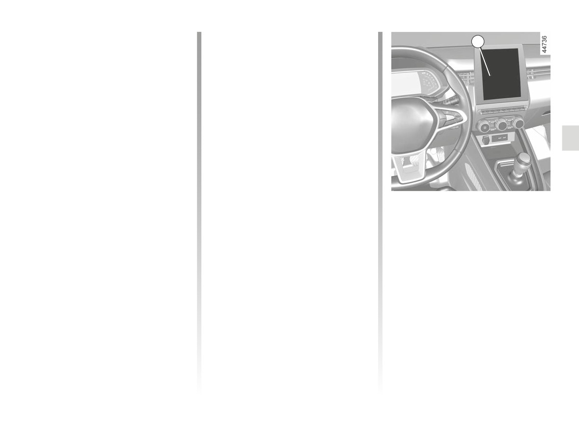
To access the function settings from the
- “Late”: line detected when cross-
multimedia screen 4 please refer to the
ing;
multimedia instructions:
- “Standard”: line detected on ap-
- “Vibration”: adjust the steering wheel
proach;
vibration level;
- “Early”: line detected nearby.
2.57
CarManuals2.co
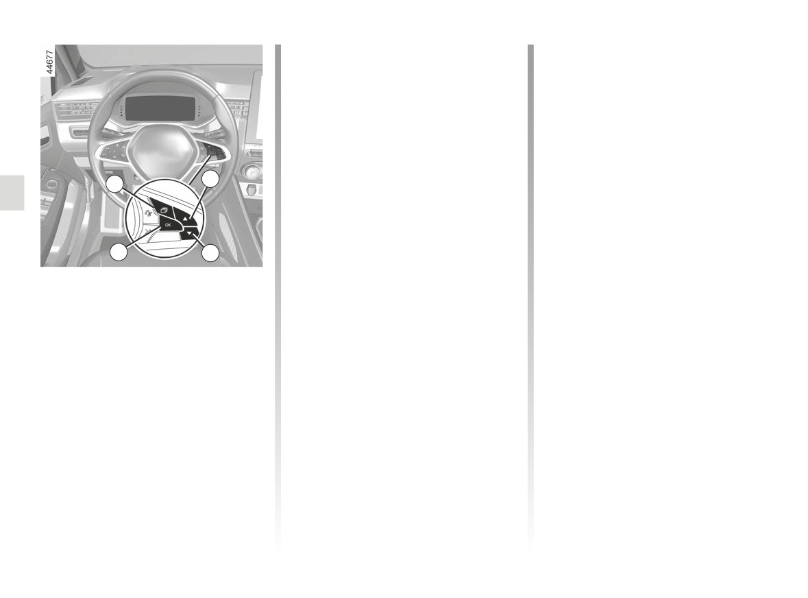
LANE KEEPING ASSIST (5/6)
- press the 6 or 7 control repeatedly to
Operating faults
reach the “DRIVING ASSIST” menu.
When the system detects an operating
Press the switch 8 OK;
fault, the
warning light appears
– press the 6 or 7 control repeatedly
on the instrument panel along with the
to reach the “Lane Keeping sensitiv-
message “Front camera to check”.
ity=#” menu. Press the switch 8 OK ;
Consult an approved dealer.
- scroll repeatedly pressing control 6
or 7 to adjust the setting. Press the 8
OK button.
6
5
8
7
Adjustments (continued)
Vehicles not fitted with a multimedia
screen
- With the vehicle stopped, press the
switch 5 as many times as required
to reach the “Vehicle” tab;
- press the 6 or 7 control repeatedly to
reach the “Settings” menu. Press the
switch 8 OK;
2.58
CarManuals2.co
LANE KEEPING ASSIST (6/6)
This function is an additional driving aid. This function is not under any circumstances intended to replace the due care
and attention of the driver, who should at all times be in control of the vehicle.
System servicing/repairs
- In the event of an impact, the camera alignment may be changed, and its operation may consequently be affected. Deactivate
the function and consult an authorised dealer.
- Any work in the area where the camera is located (repairs, replacements, windscreen modifications etc.) must be carried
out by a qualified professional.
Only an authorised dealer is qualified to service the system.
In the event of system disturbance
Some conditions can disturb or damage the operation of the system, such as:
- windscreen obscured (by dirt, ice, snow, condensation etc.);
- a complex environment (tunnel etc.);
- poor weather conditions (snow, rain, hail, black ice etc.);
- poor visibility (night, fog etc.);
- the road markings are irregular or difficult to distinguish (e.g. partially erased, excessive spacing, distorted road surface);
- being dazzled (glaring sun, lights of vehicles travelling in the opposite direction etc.);
- the road is narrow, winding or undulating (tight bends etc.);
- closely following a vehicle travelling in the same lane.
In this case, the “Lane Keeping Assist” may react incorrectly or not at all.
Risk of unwanted, incorrect correction or no correction of trajectory.
Deactivating the function
You must disable the function if:
- the area of the camera has been damaged (on the windscreen side or the interior rear-view mirror side);
- the road is slippery (snow, black ice, aquaplaning, gravel etc.) ;
- poor visibility (night, fog etc.);
- the windscreen is cracked or distorted (do not carry out windscreen repairs in this area; have it changed by an Authorised
Dealer);
- the vehicle is towing a trailer or a caravan;
- the vehicle is entering an area with several surface markings (an area with road works etc.).
2.59
CarManuals2.co
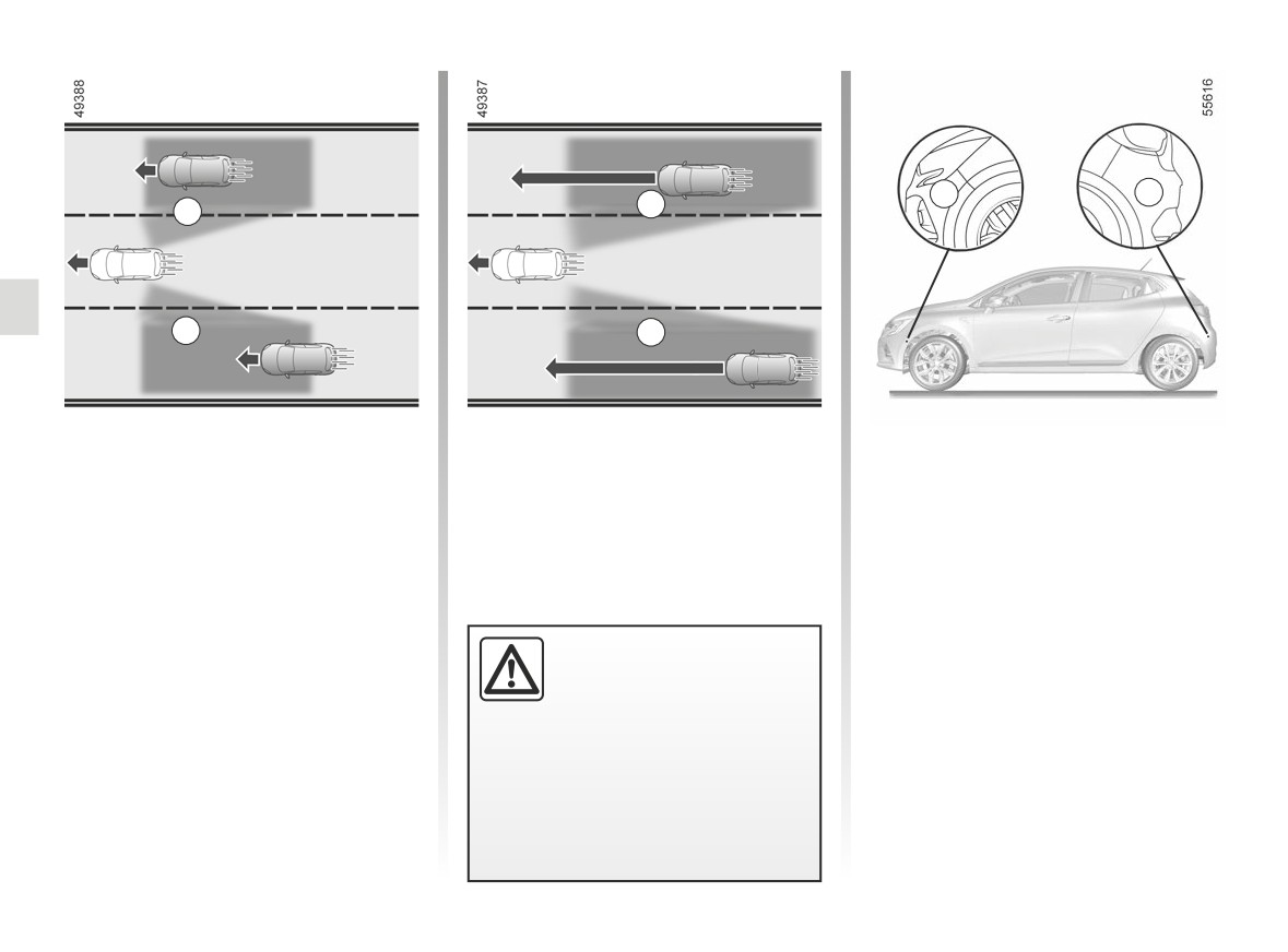
BLIND SPOT WARNING (1/7)
C
C
B
A
A
B
Using information from the sensors in-
Special feature
stalled on each side of the rear bumper
Make sure that the radar area C is not
(area C), the function warns the driver:
obscured (by stickers, mud, snow etc.).
- when another vehicle appears in the
If a radar is obscured, the message
detection area A;
“Side radars no visibility” will appear on
and/or
the instrument panel. Clean the area
where the sensors are located.
- when there is a risk of collision with
a vehicle that is in area B, driving
faster than you.
This function is an addi-
tional driving aid. This func-
The function warns you when the ve-
tion is not under any cir-
hicle is travelling at a speed above ap-
cumstances intended to
proximately 9 mph (15 km/h).
replace the due care and attention
of the driver, who should at all times
be in control of the vehicle.
2.60
CarManuals2.co
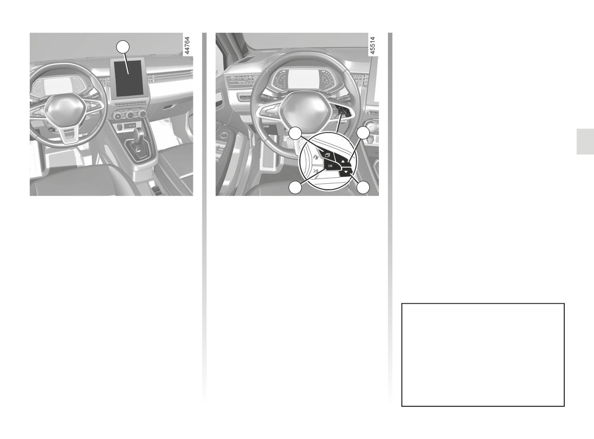
BLIND SPOT WARNING (2/7)
- press the switch 5 OK again to acti-
1
vate or deactivate the function:
=
function activated
<
function deactivated
2
3
5
4
Activation/deactivation
- press the 3 or 4 control repeatedly to
reach the “Settings” menu. Press the
Vehicles fitted with a multimedia
switch 5 OK;
screen 1
- press the 3 or 4 control repeatedly to
To activate or deactivate the function,
reach the “DRIVING ASSIST” menu.
refer to the multimedia instructions.
Press the switch 5 OK;
Select “ON” or “OFF”.
- press the 3 or 4 control repeatedly to
reach the “Blind spot alert” menu and
Vehicles not fitted with a multimedia
press the 5 OK switch;
screen
- With the vehicle stopped, press the
switch 2 as many times as required
The system’s detection range oper-
to reach the “Vehicle” tab;
ates according to a standard lane
width. When driving in a narrow
lane, the function may warn you
when a vehicle is detected further
away than the nearest lane.
2.61
CarManuals2.co
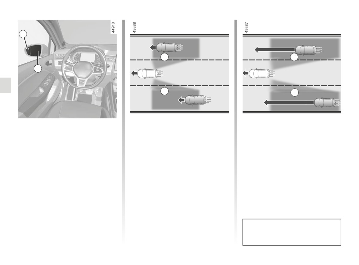
BLIND SPOT WARNING (3/7)
6
A
B
7
A
B
Indicator 6
Operation
An indicator light 6 is located on each
The function warns you when the speed
rear view mirror 7.
of your vehicle is over approximately
9 mph (15 km/h) and:
Note: clean the rear view mirrors 7 reg-
- when another vehicle is in the blind
ularly so that the indicators 6 can be
spot area A and travelling in the
seen.
same direction as your vehicle;
- when a vehicle approaches quickly
from the rear in an adjacent lane
within the range of detection area B.
If you overtake another vehicle, the in-
dicator 6 will only come on if that vehi-
cle remains for a long enough period in
your vehicle’s blind spot A.
The function does not notify the
driver if the other vehicles are not
moving.
2.62
CarManuals2.co
BLIND SPOT WARNING (4/7)
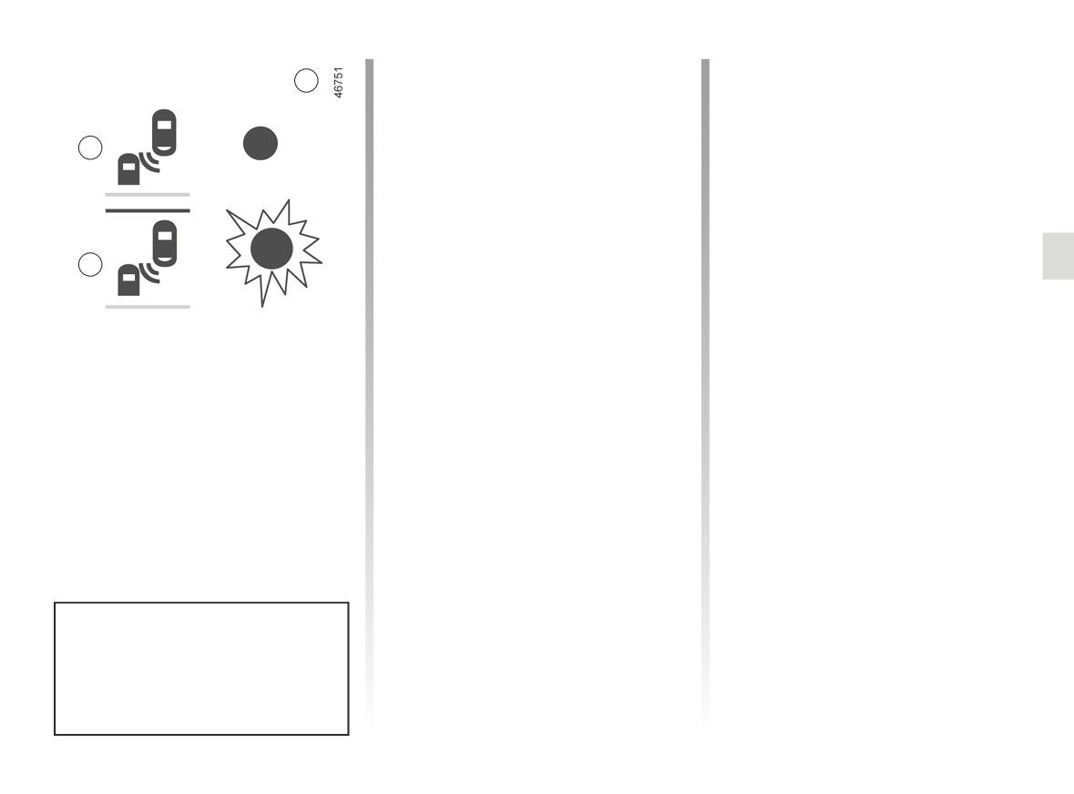
Display E
Conditions for non-function
6
Direction indicator activated, the 6
- When driving on a road with tight
warning light flashes when the func-
bends;
tion detects a vehicle in the blind spot
- in reverse.
D
warning area and/or a vehicle is rapidly
approaching from the rear on the side
If the vehicle is equipped with a towbar
towards which you will turn the wheel.
recognised by the system, the “Trailer:
If you cancel the direction indicator, the
blind spot alert off” message displayed
function will return to the initial warning
on the instrument panel informs you
(display D).
that the function is not operational. For
E
information on the range of equipment
adapted to your vehicle, we advise you
to consult an approved Dealer.
Display D
First warning: direction indicator not
activated, the 6 warning light indicates
that a vehicle is detected in the blind
spot area and/or that a vehicle is rap-
idly approaching from the rear in an ad-
jacent lane.
When the engine is started, the
system adopts the last status saved
before the ignition was switched off
(refer to the previous pages).
2.63
CarManuals2.co
BLIND SPOT WARNING (5/7)
Operating faults
If the system detects a fault, the mes-
sage “Side radars to check” is displayed
on the instrument panel. Consult an ap-
proved dealer.
- The system’s detection
range operates according
to a standard lane width. If
you are driving in wide traf-
fic lanes, the system might not
be able to detect a vehicle in the
blind spot.
- The system might be disrupted
momentarily if it is exposed to
strong electromagnetic waves
(as beneath high-tension power
lines) or to very poor weather
conditions
(heavy rain, snow
etc.). Remain aware of driving
Due to the presence of sensors
conditions.
behind the bumper, it is advisable to
entrust any operation on the bumper
There is a risk of accidents.
(repair, replacement, paintwork,
etc.) to a qualified professional.
2.64
CarManuals2.co
BLIND SPOT WARNING (6/7)
This function is an additional driving aid. This function is not under any circumstances intended to replace the due care
and attention of the driver, who should at all times be in control of the vehicle.
The driver should always adapt their speed to the traffic conditions, regardless of the system indications.
The system should under no circumstances be taken to be an obstacle detector or an anti-collision system.
System servicing/repairs
- In the event of an impact, radar alignment may be changed, and its operation will consequently be affected. Deactivate the
function and consult an authorised dealer.
- Any work in the area where the radars are located (repairs, replacements, etc.) must be carried out by a qualified profes-
sional.
Only an authorised dealer is qualified to service the system.
System disturbance
Some conditions can disturb or damage the operation of the system, such as:
- complex surroundings (metal bridges, tunnels, roads with barriers at the edge, etc.);
- poor weather conditions (snow, hail, black ice, etc.).
Risk of false alarms or absence of warnings
In the event of the system behaving abnormally, deactivate it and consult an authorised dealer.
2.65
CarManuals2.co
BLIND SPOT WARNING (7/7)
Limitation of the system operation
- The radar area should be kept clean and free of any modifications in order to ensure the proper operation of the
system.
- Small objects moving close to the vehicle (motorcycles, bicycles, pedestrians, etc.) may not be recognised by the system.
- When turning into a bend, the radars may temporarily cease to detect vehicles in adjacent lanes.
- The function may warn you late when two other vehicles are approaching from the rear, side by side in the adjacent lanes
(driving on a 3-lane road) and at a much higher speed than your vehicle.
- The system may not provide a warning when the other vehicles are travelling at a significantly different speed.
- If the vehicle is being overtaken by a long vehicle (e.g. heavy goods vehicle overtaking at a similar speed to the vehicle) the
system may interrupt the warning before the end of the manoeuvre.
- The vehicle is travelling on a winding road.
Deactivating the function
You must disable the function if:
- the radar area has been damaged (rear bumper);
- the vehicle is fitted with a towbar that is not recognised by the system.
2.66
CarManuals2.co
SAFE DISTANCE ALERT (1/4)
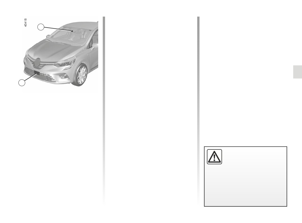
The function is activated when the vehi-
cle speed is between about 19 and
1
124 mph (30 and 200 km/h).
Location of the camera 1
Make sure the windscreen is not ob-
scured (by dirt, mud, snow, condensa-
tion etc.).
Location of the radar 2
2
Ensure that the radar area is not ob-
structed (by dirt, mud, snow, a badly
fitted front number plate), impacted,
modified (including painting) or hidden
Using the information from the radar 2
by any accessory fitted on the front of
and camera 1, this function informs the
the vehicle (on the grille or logo etc.).
driver of the time interval between their
vehicle and the vehicle in front so that a
safe stopping distance between the two
vehicles can be maintained.
This function is an addi-
tional driving aid. This func-
tion is not under any cir-
cumstances intended to
replace the due care and attention
of the driver, who should at all times
be in control of the vehicle.
2.67
CarManuals2.co
SAFE DISTANCE ALERT (2/4)
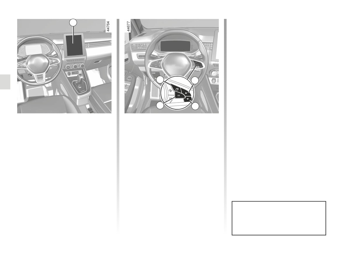
- press the 5 or 6 control repeatedly to
3
reach the “Distance warning” menu.
Press the switch 7 OK;
- Press the switch 7 OK again to acti-
vate or deactivate the function:
=
function activated
<
function deactivated
4
5
7
6
Activating/deactivating the
Vehicles not fitted with a multimedia
screen
function
- With the vehicle stopped, press the
Vehicles fitted with a multimedia
switch 4 as many times as required
screen 3
to reach the “Vehicle” tab;
To activate or deactivate the function,
- press the 5 or 6 control repeatedly to
refer to the multimedia instructions.
reach the “Settings” menu. Press the
Select “ON” or “OFF”.
switch 7 OK;
- press the 5 or 6 control repeatedly to
reach the “DRIVING ASSIST” menu.
Press the switch 7 OK;
Each time the vehicle is started,
the function continues the mode
saved the last time the engine was
stopped.
2.68
CarManuals2.co
SAFE DISTANCE ALERT (3/4)
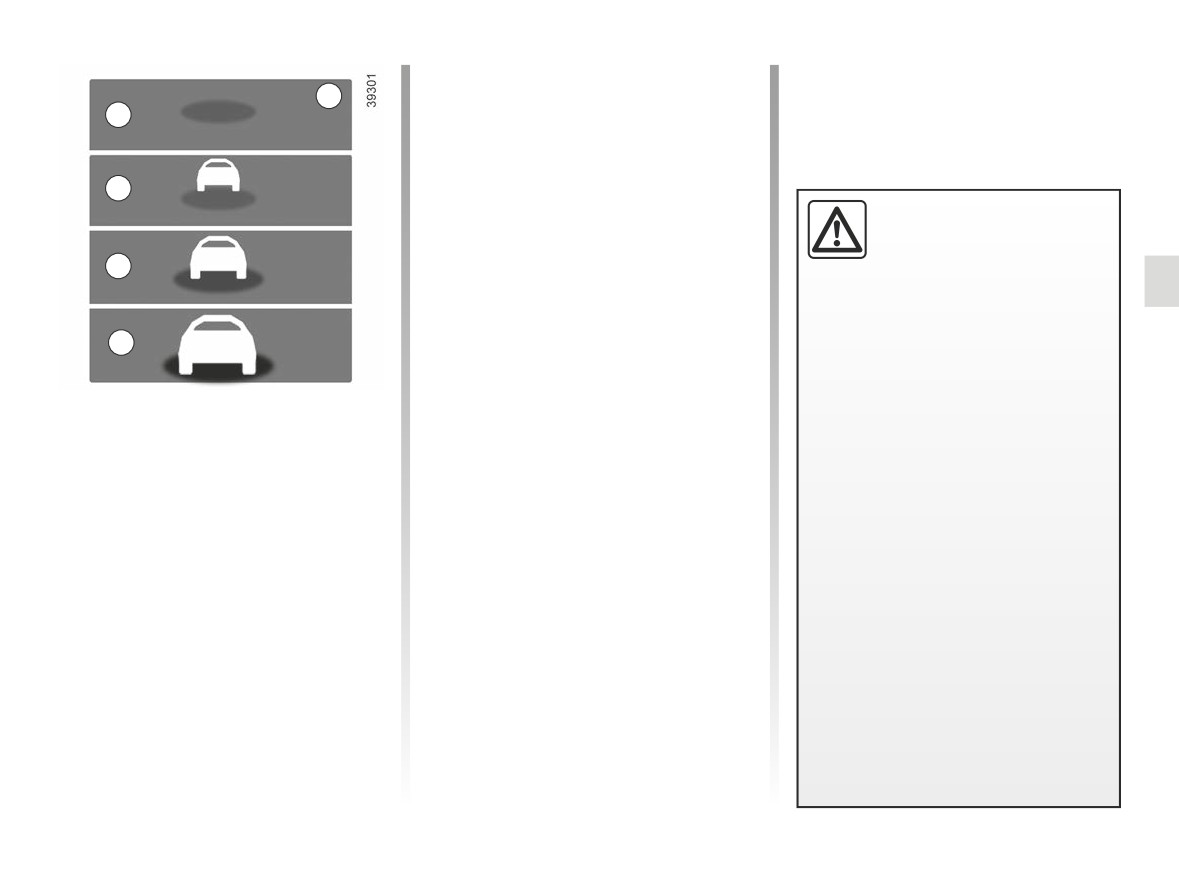
- C (orange): the time interval falls be-
8
tween around 1 and 2 seconds (in-
A
sufficient distance between the two
vehicles);
- D (red): the time interval is less than
B
or equal to around one second (very
insufficient distance between the two
The measurement is dis-
vehicles).
played for information: the
If the interval between the two vehi-
system does not carry out
C
cles is less than approximately 0.5 sec-
any action on the vehicle.
onds, the 8 indicator and the D display
This function is not designed for use
will flash in red on the instrument panel
in urban conditions or for a dynamic
D
along with “-.- s”.
driving style (sudden cornering, ac-
Under certain conditions, the time inter-
celeration, braking, etc.), but rather
val may not be displayed:
for stable driving conditions.
Operation
- while cornering;
The function does not interact with
With the function activated, the 8 in-
the braking system.
- when changing lane;
dicator is displayed on the instrument
The radar and camera zones must
panel and informs the driver of the dis-
- if the vehicle in front is sufficiently far
be kept clean and free of any tam-
tance between their vehicle and the ve-
or outside the range of the radar or
pering in order to ensure the proper
hicle in front.
camera.
operation of the system.
- A (grey): function not operational;
Any work carried out in the area
- A (green): no vehicle detected;
where the radar or camera is lo-
cated (repairs, replacements, wind-
- B (green): the time interval is greater
screen and/or bumper modifica-
than or equal to around two seconds
tions, etc.) must be carried out by a
(distance between the two vehicles
qualified professional.
adapted to your speed);
2.69
CarManuals2.co
SAFE DISTANCE ALERT (4/4)
This function is an additional driving aid. This function is not under any circumstances intended to replace the due care
and attention of the driver, who should at all times be in control of the vehicle.
System servicing/repairs
- In the event of an impact, the radar and/or camera alignment may be changed and its operation may consequently be af-
fected. Deactivate the function and consult an authorised dealer.
- Any work carried out in the area where the radar and/or camera is located (replacements, repairs, windscreen and/or
bumper modifications, etc.) must be carried out by a qualified professional.
Only an authorised dealer is qualified to service the system.
In the event of disruption to the radar area system
- obstruction of the windscreen or the radar area (by dirt, ice, snow, condensation etc.);
- a complex environment (metal bridge, tunnel etc.);
- poor weather conditions (snow, hail, black ice etc.);
- poor visibility (night, fog etc.);
- poor contrast between the vehicle preceding it and the surrounding area (e.g. white vehicle in a snowy area etc.) ;
- being dazzled (glaring sun, lights of vehicles travelling in the opposite direction etc.);
- the road is narrow, winding or undulating (tight bends etc.)
Risk of erroneous false alarms.
2.70
CarManuals2.co
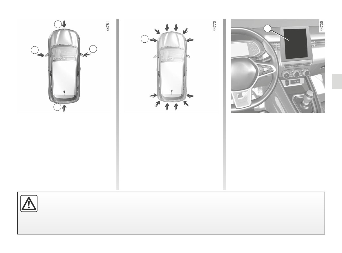
360° CAMERA (1/9)
1
5
4
2
2
3
Using information from cameras 1, 2,
Operation
- front side view (depending on the ve-
and 3 located in the front bumper, door
hicle): using camera 2 (passenger
The cameras transmit four separate
mirrors and on the tailgate, as well as
side).
views to the multimedia screen 5.
ultrasonic detectors 4 located in the ve-
They enable you to view the vehicle
The ultrasonic detectors detect obsta-
hicle bumpers, the feature assists with
surroundings:
cles at the front, rear and (depending
difficult manoeuvres (e.g. parking) by
- front view: using camera 1;
on the vehicle) side of the vehicle.
displaying the vehicle surroundings.
- rear view: using camera 3;
Note: make sure that the cameras are
- bird’s eye view: using cameras 1, 2
not obscured (by dirt, mud, snow etc.).
and 3;
This function is an additional aid. It cannot, therefore, under any circumstances replace the vigilance or the responsi-
bility of the driver.
The driver should always be ready for sudden incidents while driving: always ensure that there are no small, narrow
moving obstacles (such as a child, animal, pushchair, bicycle, stone, post, etc.) in the blind spot when manoeuvring.
2.71
CarManuals2.co
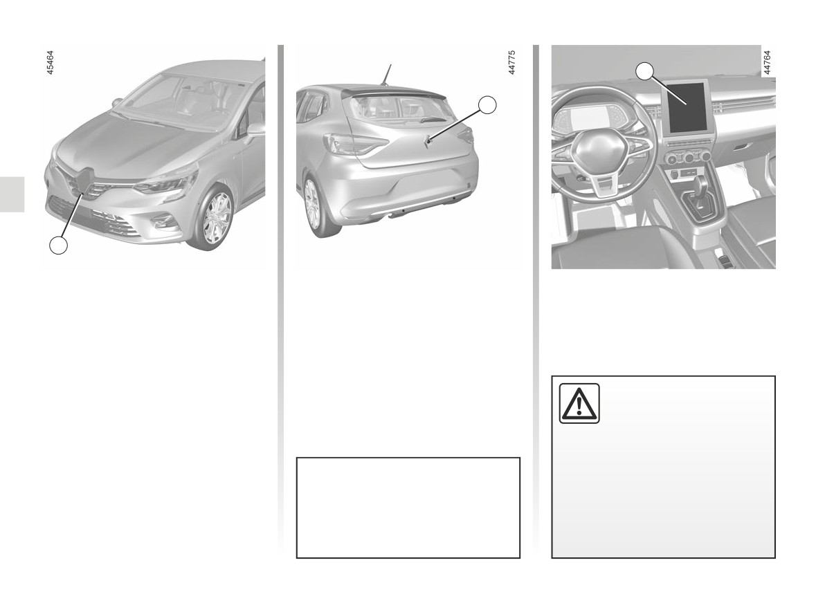
360° CAMERA (2/9)
5
3
1
Front view 1
Rear view 3
The view of the front camera is dis-
The view of the rear camera is dis-
played on the multimedia screen 5.
played on the multimedia screen 5.
In front view or rear view:
when manoeuvring on a
slope, objects shown on
the multimedia screen may
be closer or further away than they
seem.
Take this into account in order
The 5 multimedia screen shows a
to correctly assess the distance
reverse image of the rear view 3 as
before any manoeuvre.
in a rear view mirror.
2.72
CarManuals2.co
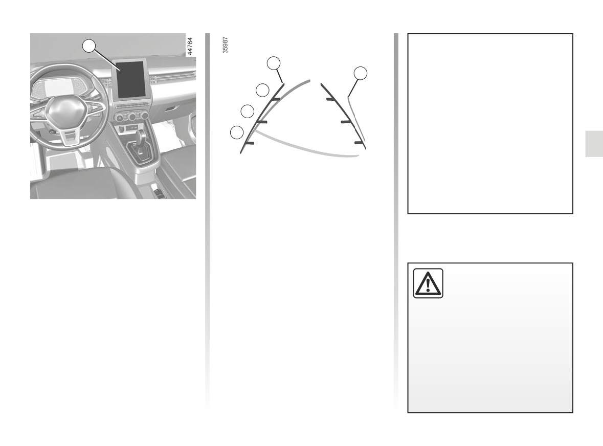
360° CAMERA (3/9)
5
The front, rear and side view guide-
6
7
lines are a representation projected
onto flat ground; this information
C
must not be taken into account
when superimposed on a vertical
B
object or an object on the ground.
Objects displayed on the edge of
A
the multimedia screen may appear
distorted.
In very bright light (snow, vehicle in
sunshine etc.), the camera vision
may be adversely affected.
Fixed clearance gauge 6
The fixed clearance gauge comprises
coloured markers A, B and C indicating
The “front” or “rear” view transmitted to
the distance behind the vehicle:
the multimedia screen 5 is displayed
- A(red) approximately 30 centime-
with one or two guidelines 6 and 7.
tres from the vehicle;
This system is initially used with the aid
- B(yellow) approximately 70 centi-
of several gauges (mobile for trajectory
metres from the vehicle;
In the combined represen-
and fixed for distance).
- C(green) approximately 150 centi-
tation from the cameras:
metres from the vehicle.
- raised objects (pavement,
Dynamic gauge 7 (depending on the
vehicle, etc.) may appear
vehicle)
distorted in bird’s eye view;
This is shown in blue on the multime-
- any objects on top of the vehicle
dia screen 5. It indicates the vehicle tra-
are not displayed.
jectory according to the position of the
steering wheel in the front and the rear
view.
2.73
CarManuals2.co
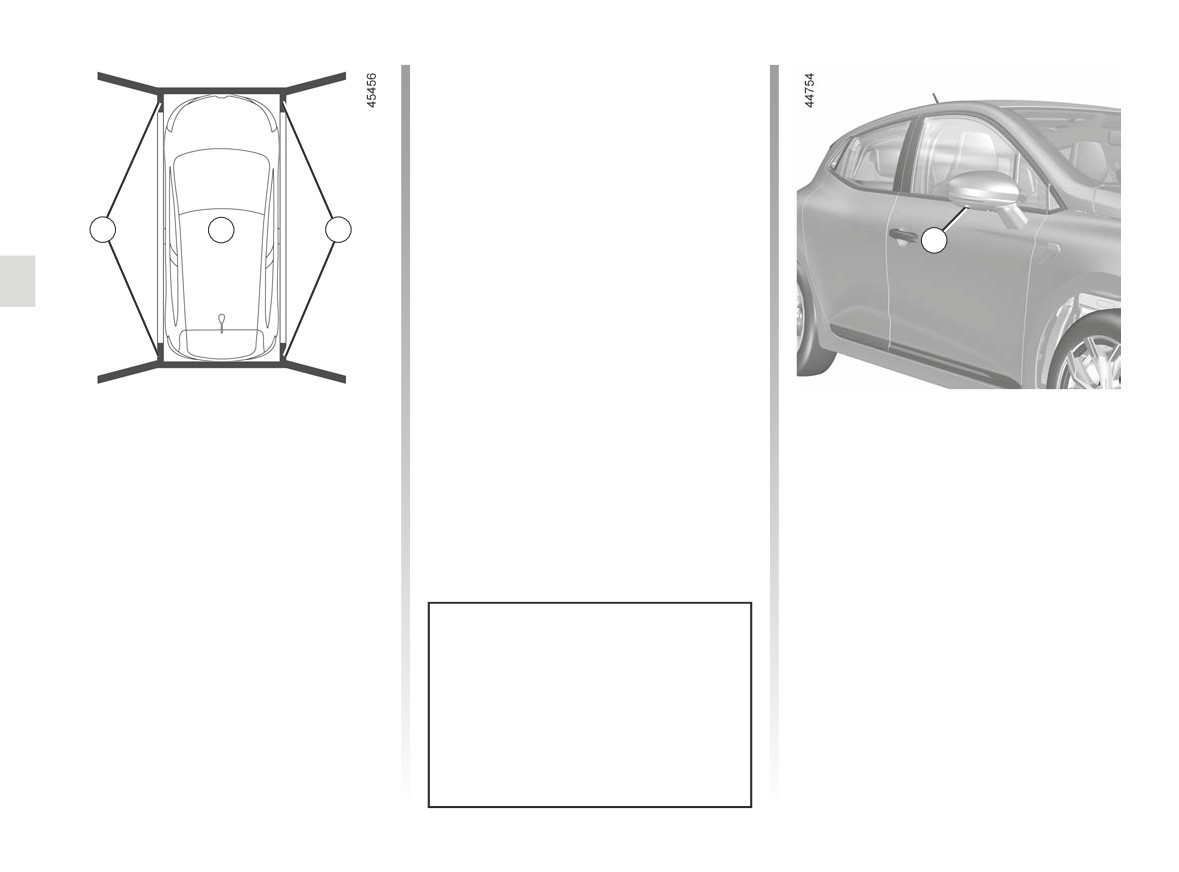
360° CAMERA (4/9)
9
8
9
2
Bird’s eye view
Front side view on passenger
The bird’s eye view is a combined rep-
side 2
resentation from cameras 1, 2 and 3.
(depending on the vehicle)
It displays a view of the top of the vehi-
The camera, fitted in the door mirror,
cle and its surroundings.
transmits a side view to the multimedia
screen 5.
This can be used to confirm a view of
the vehicle position in relation to its im-
Depending on the vehicle, you can use
mediate surroundings (front, rear and
the multimedia screen to change the
side).
bird’s eye view to the front side view.
Please refer to the multimedia instruc-
The 8 view indicates the vehicle posi-
In “bird’s eye view” mode, the ob-
tions for further information.
tion. 9 areas not covered by the cam-
jects displayed on the multimedia
eras are indicated in black.
screen are actually further away
than they seem.
Take this into account in order
to correctly assess the distance
before any manoeuvre.
2.74
CarManuals2.co
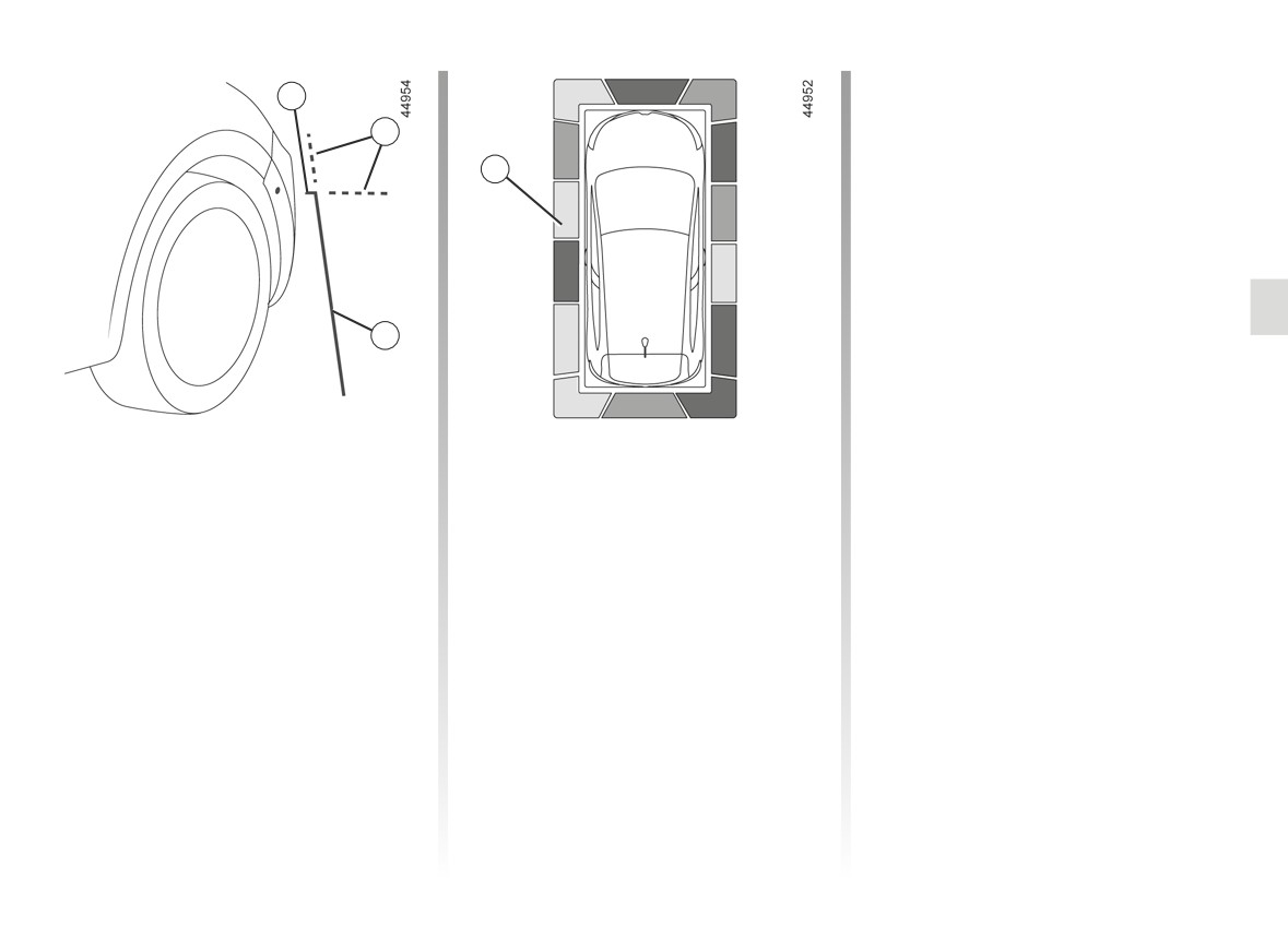
360° CAMERA (5/9)
In addition to the sound alert, these in-
10
dicator lines show the proximity of ob-
stacles via different colours:
11
- Green: obstacle between approxi-
13
mately 50 and 70 cm;
- Yellow: obstacle between approxi-
mately 30 and 50 cm;
- Red: obstacle within approximately
30 cm.
These indicator lines also show the
12
location where the obstacles are de-
tected, as indicated by their positions in
relation to the “vehicle” symbol.
For more information ➥ 2.131.
The “Front side view on passenger
Depending on the vehicle, you can use
side” is transmitted to the multimedia
the multimedia screen to change the
screen with fixed guidelines to measure
bird’s eye view to the front side view.
the distances.
Please refer to the multimedia instruc-
tions for further information.
Fixed guidelines 10, 11 and 12
Fixed guideline 10 shows the front sec-
Obstacle detection
tion of the vehicle.
Fixed guideline 12 shows the vehicle
While the system is activated, if the
width including door mirrors.
“Park Assist” function detects one or
Fixed guidelines 11 are shown in red
more obstacles around the vehicle,
and dotted. These are extensions of
the 13 indicator lines display:
fixed guidelines 10 and 12.
- on the bird’s eye view;
- on the front side view on the passen-
ger side (depending on the vehicle).
2.75
CarManuals2.co
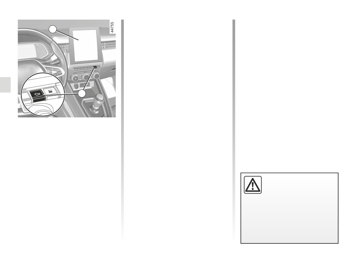
360° CAMERA (6/9)
Automatic mode is disabled:
5
- when the gear lever is in neutral
(manual gearbox) or in position N or
P (automatic gearbox) for approxi-
mately three seconds;
- when the vehicle speed moving for-
ward exceeds 6 mph (10 km/h).
Manual mode
To activate manual mode, with the ve-
hicle stopped and the engine running,
14
press the 14 switch: the front view and
bird’s eye view appear on the multime-
dia screen.
Manual mode is disabled:
Activation/deactivation
- when the vehicle speed moving for-
ward reaches 6 mph (10 km/h);
Automatic mode
- when the gear lever has not been
With the ignition switched on, automatic
used for approximately three min-
mode is activated when reverse gear is
utes;
engaged. The rear view and the bird’s
- when you press the 14 button.
eye view appear on the 5 multimedia
screen.
When the reverse gear is quickly shifted
-Do not use this function
to forward gear, the rear view and bird’s
while the door mirrors are in
eye view are replaced by the front view
folded position.
and bird’s eye view on the 5 multimedia
-Ensure that the luggage
screen.
compartment door is properly
closed before using the function.
- Do not place any objects on or in
front of the cameras.
2.76
CarManuals2.co
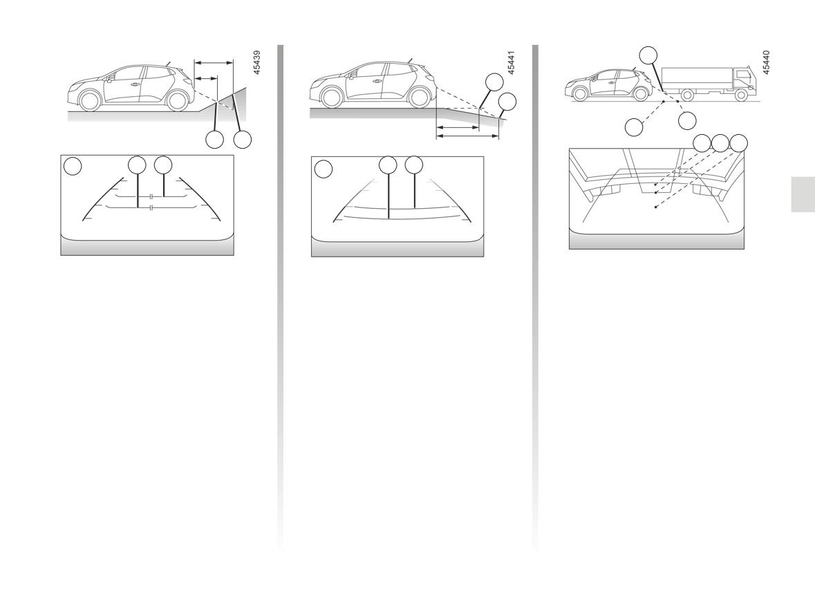
360° CAMERA (7/9)
H
F
G
J
K
D E
H J
K
15
D E
F G
15
Difference between the
Driving or reversing towards a steep
Driving or reversing towards a
downhill slope
protruding object
estimated distance and
actual distance
The fixed guidelines 15 show the dis-
Position H seems further than posi-
tances as further than they actually are.
tion J on the screen. However, posi-
Driving or reversing towards a steep
tion H is at the same distance as posi-
Therefore, the objects shown on the
uphill slope
tion K.
screen are actually closer on the slope.
The fixed guidelines 15 show the dis-
The trajectory indicated by the fixed
For example, if the screen displays an
tances as closer than they actually are.
and mobile guidelines do not take into
object at G, the actual distance of the
account the height of the object. So
The objects shown on the screen are
object is at F.
there is a risk that the vehicle may col-
actually further away on the slope.
lide with the object when reversing to-
For example, if the screen displays an
wards position K.
object at D, the actual distance of the
object is at E.
2.77
CarManuals2.co
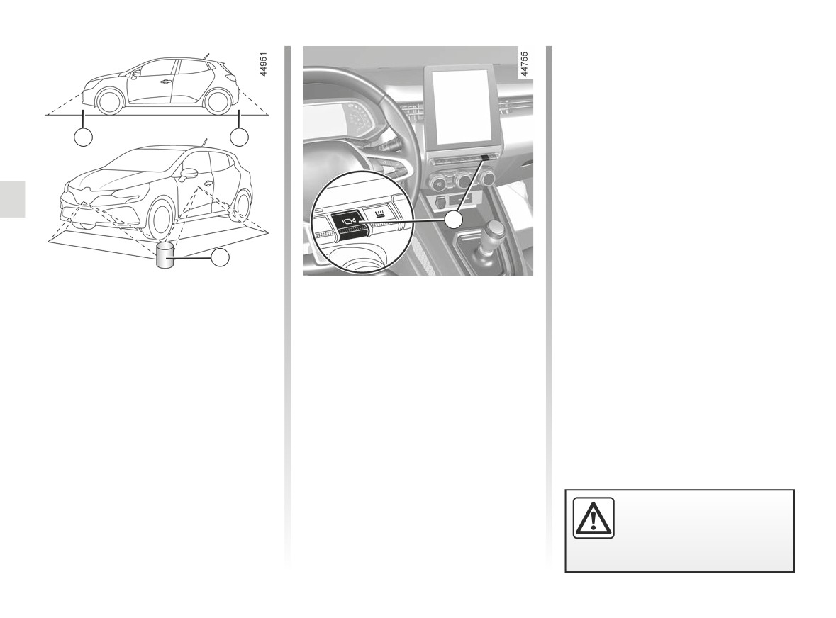
360° CAMERA (8/9)
L
L
14
M
Limitations of system operation
Adjusting the display
The system is unable to display objects
With the ignition on, press the 14 switch
located in certain areas.
or move the selection lever to posi-
tion R (on an automatic gearbox) or to
In the front or rear view mode, the
reverse gear (on a manual gearbox) in
system cannot be used to view an
order to use the feature.
object in area L.
The function displays different views on
In bird’s eye view mode, the system
the screen according to the gear lever
cannot be used to view a large object in
position.
area M (near the edge of the displayed
area).
Depending on the vehicle, you can
select the “bird’s eye view” or “front side
view on the passenger side”.
For safety reasons, carry
out any adjustments when
the vehicle is not being
driven.
2.78
CarManuals2.co
360° CAMERA (9/9)
If the gear lever is in position R (on an
When shifting from reverse gear to po-
Adjusting the camera
automatic gearbox) or in reverse (on a
sition D (on an automatic gearbox) or
settings
manual gearbox), the following views
into a gear (on a manual gearbox), the
The following settings can be modified:
are available:
following views are available:
- brightness;
- screen split between the rear view/
- screen split between the front view/
- colours;
bird’s eye view;
bird’s eye view;
- contrast.
or
or
- screen split between the rear view/
- screen split between the front view/
Please refer to the multimedia instruc-
front side view (depending on the ve-
front side view (depending on the ve-
tions for further information.
hicle).
hicle).
Note: for safety reasons, the views are
When shifting from reverse gear to po-
not displayed in the “Settings” menu
sition P (on an automatic gearbox) or to
while the vehicle is moving.
neutral position (on a manual gearbox),
the following views are available:
- screen split between the rear view/
bird’s eye view;
or
- screen split between the rear view/
front side view (depending on the ve-
hicle).
2.79
CarManuals2.co
ACTIVE EMERGENCY BRAKING (1/8)
Depending on the reactivity of the
driver, the system can assist with brak-
1
ing in order to limit damage or prevent
a collision.
Note: ensure that the windscreen and
front bumper are not obstructed (by
dirt, mud, snow, condensation, number
plate, etc.).
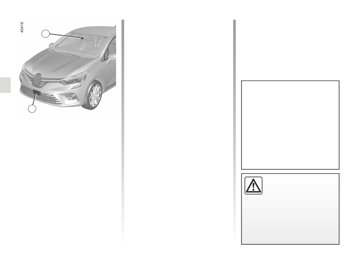
Location of the camera 1
Make sure the windscreen is not ob-
scured (by dirt, mud, snow, condensa-
This system can apply maximum
tion etc.).
braking to the vehicle until it is
2
completely stationary if necessary.
For safety reasons, always wear
The system uses information from the
Location of the radar 2
your seat belt when travelling in
radar 2 and the camera 1 to determine
Ensure that the radar area is not ob-
your vehicle and make sure that it
the distance from your vehicle:
structed (by dirt, mud, snow, a badly
is loaded so that no items can be
- from the vehicle ahead in the same
fitted front number plate), impacted,
thrown forward and hit the occu-
lane;
modified (including painting) or hidden
pants.
by any accessory fitted on the front of
or
the vehicle (on the grille or logo etc.).
- surrounding pedestrians and cy-
clists.
This function is an addi-
The system informs the driver if there
tional driving aid. This func-
is a risk of head-on collision to enable
tion is not under any circum-
appropriate emergency manoeuvres
stances intended to replace
(pressing the brake pedal and/or turn-
the due care and attention of the
ing the steering wheel).
driver, who should at all times be
in control of the vehicle.
2.80
CarManuals2.co
ACTIVE EMERGENCY BRAKING (2/8)
Operation
Special features of warnings
Depending on the speed, the warning
Detection of vehicles
and braking may be activated simulta-
When driving, in the event of a risk of
neously.
collision with the vehicle in front the
system will:
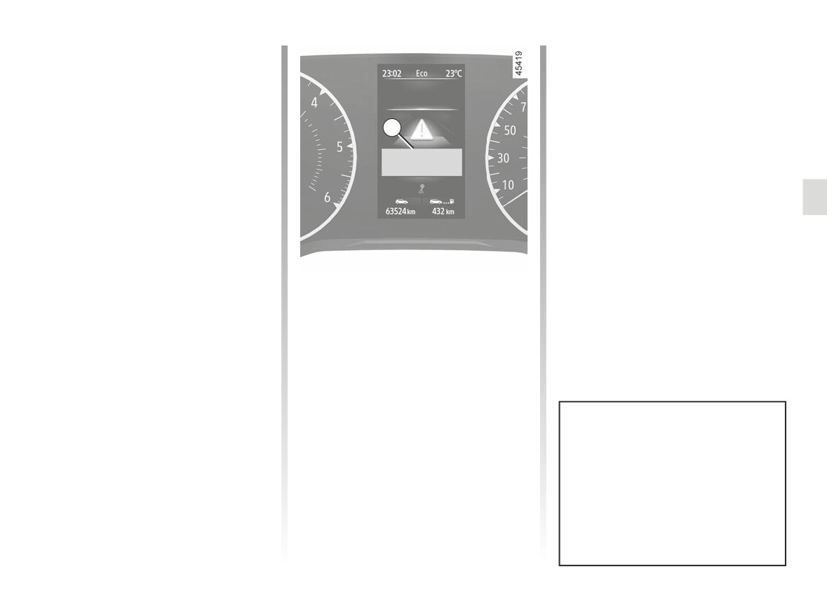
3
Special features of stationary
– warns you of a collision risk:
vehicles
When the vehicle speed is between
Stationary vehicles are detected when
approximately 4 mph (7 km/h) and
your vehicle is being driven at a speed
106 mph (170 km/h), the message
between approximately 4 mph (7 km/h)
“Brake” is displayed in red on the in-
and 50 mph (80 km/h). The system is
strument panel 3 accompanied by a
not active and does not emit a warning
beep.
for stationary vehicles when you exceed
If the driver depresses the brake
approximately 50 mph (80 km/h).
pedal and the system still detects a
risk of collision, the brake force is in-
If active emergency braking has caused
creased.
the vehicle to stop, the vehicle is kept
- may trigger braking:
stationary for a short time. Beyond this
when the vehicle speed is below ap-
time limit, the vehicle must be held sta-
proximately 75 mph (120 km/h), if the
tionary by the driver keeping their foot
driver does not respond to the warn-
on the brake pedal.
ing and a collision is imminent.
Note: if the driver uses the vehicle con-
trols (steering wheel, pedals, etc.) the
system may delay certain operations or
not activate.
In the event of emergency manoeu-
vre, you can stop braking at any
moment by:
- tapping the accelerator pedal;
or
- turning the steering wheel as a
collision avoidance manoeuvre.
2.81
CarManuals2.co
ACTIVE EMERGENCY BRAKING (3/8)
Detection of pedestrians and
Special features of warnings
cyclists
Depending on the speed, the warning
(depending on the vehicle)
and braking may be activated simulta-
When driving at a speed between ap-
neously.
proximately 4 mph (7 km/h) and 50 mph
(80 km/h), if there is a risk of col-
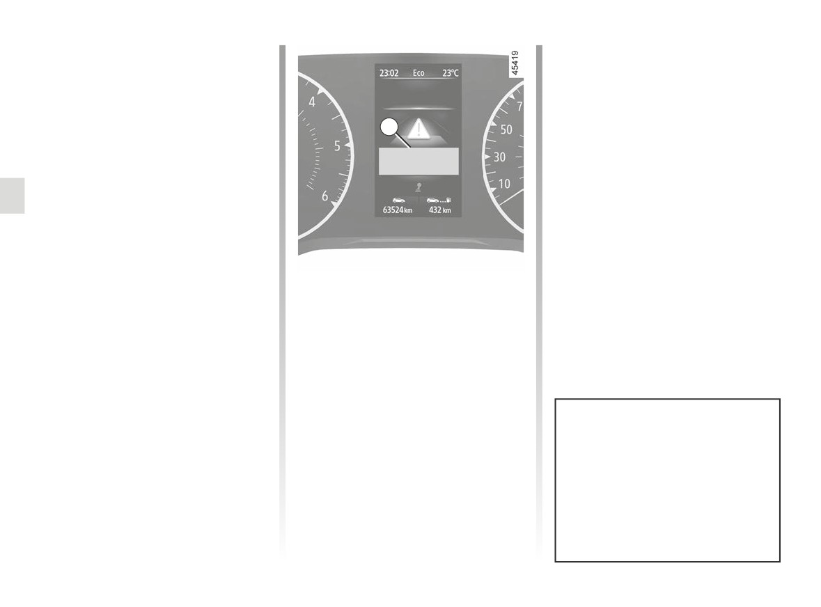
3
lision with a cyclist or a pedestrian, the
system:
- warns you of a risk of collision: the
red
warning light or, depend-
ing on the vehicle, 3 and the “Brake”
message are displayed on the instru-
ment panel accompanied by a beep.
If the driver presses the brake pedal
and the system still detects a risk of
If active emergency braking has caused
collision, the braking force may be in-
the vehicle to stop, the vehicle is kept
creased if it is not sufficient to pre-
stationary for a short time. Beyond this
vent the collision.
time limit, the vehicle must be held sta-
tionary by the driver keeping their foot
- braking may be triggered: if the
on the brake pedal.
driver does not react following the
warning and the collision is immi-
Note: if the driver uses the vehicle con-
nent.
trols (steering wheel, pedals, etc.) the
system may delay certain operations or
not activate.
In the event of emergency manoeu-
vre, you can stop braking at any
moment by:
- tapping the accelerator pedal;
or
- turning the steering wheel as a
collision avoidance manoeuvre.
2.82
CarManuals2.co
ACTIVE EMERGENCY BRAKING (4/8)
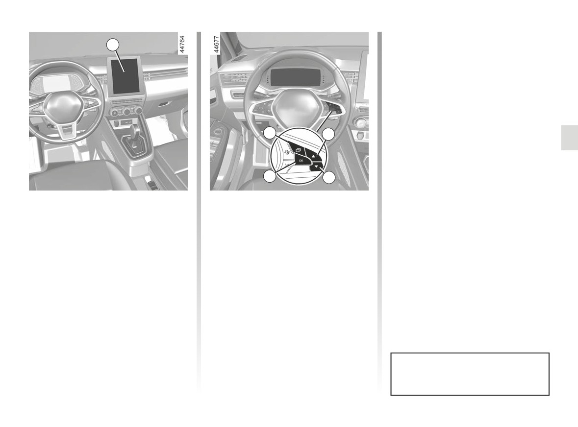
- press the 6 or 7 control repeatedly to
4
reach the “Active braking” menu and
press the 8 OK switch.
Press the switch 8 OK again to activate
or deactivate the function:
=
function activated
<
function deactivated
Upon deactivation of the system, the
5
6
warning light illuminates or, de-
pending on the vehicle, the
warning light illuminates on the instru-
8
7
ment panel.
Activating or deactivating the
For vehicles not fitted with a
multimedia screen
system
- With the vehicle stopped, press the
Vehicles fitted with a multimedia
switch 5 as many times as required
screen 4
to reach the “Vehicle” tab;
To activate or deactivate the function,
- press the 6 or 7 control repeatedly to
please refer to the multimedia instruc-
reach the “Settings” menu. Press the
tions.
switch 8 OK;
- press the 6 or 7 control repeatedly to
Select “ON” or “OFF”.
reach the “DRIVING ASSIST” menu.
Press the switch 8 OK;
This system is reactivated each time
the ignition is switched on.
2.83
CarManuals2.co
ACTIVE EMERGENCY BRAKING (5/8)
Temporarily not available
Operating faults
If the system detects a temporary
When the function detects an operat-
fault the
warning light illumi-
ing fault, the
and
warn-
nates, or depending on the vehicle the
ing lights, or
(depending on the
warning light illuminates on the
vehicle) appear in yellow on the instru-
instrument panel.
ment panel accompanied by one of
the following messages: “Check Front
The possible causes are:
camera” or “Front radar to check” or
- the system is temporarily blinded
“Check Camera/Radar”.
(glare from the sun, dipped beam
headlights, bad weather conditions
Consult an approved dealer.
etc.). The system will be operational
again when visibility conditions are
better;
- the system is temporarily interrupted
(e.g. the windscreen, front bumper
grille or logo is obscured by dirt,
mud, snow, condensation, etc.). In
this case, park the vehicle and switch
off the engine. Clean the wind-
screen, the front bumper or the logo.
The next time the engine is started,
after five or ten minutes of driving,
the warning light and the message
disappear.
If this is not the case, this may arise from
another cause; contact an Approved
Dealer.
2.84
CarManuals2.co
ACTIVE EMERGENCY BRAKING (6/8)
Active emergency braking
This function is an additional driving aid. This function is not under any circumstances intended to replace the due care
and attention of the driver, who should at all times be in control of the vehicle. The triggering of this function may be
delayed or prevented when the system detects clear signs of control of the vehicle by the driver (action on the steer-
ing wheel, pedals etc.).
The system cannot be activated:
- when the gearbox lever is in neutral or the clutch pedal has been depressed during approximately ten seconds;
- when the parking brake is activated;
- when the Electronic Stability Program (ESC) has started.
System servicing/repairs
- In the event of an impact, the radar and/or camera alignment may be changed and its operation may consequently be af-
fected. Deactivate the function and consult an authorised dealer.
- Any work in the area where the radar and/or camera is located (repairs, replacements, windscreen modifications, etc.) must
be carried out by a qualified professional.
Only an authorised dealer is qualified to service the system.
2.85
CarManuals2.co
ACTIVE EMERGENCY BRAKING (7/8)
System disturbance
Some conditions can disturb or damage the operation of the system, such as:
- a complex environment (metal bridge, tunnel etc.);
- poor weather conditions (snow, hail, black ice etc.);
- poor visibility (night, fog etc.);
- poor contrast between the object (vehicle, pedestrian etc.) and the surrounding area (e.g. pedestrian dressed in white lo-
cated in a snowy area etc.);
- being dazzled (glaring sun, lights of vehicles travelling in the opposite direction etc.);
- obstruction of the windscreen or the radar area (by dirt, ice, snow, condensation etc.);
- ...
In these conditions, the system may not react, may warn the driver or may brake inadvertently.
Limitation of the system operation
- Each time the vehicle is started, the system carries out a calibration according to the vehicle surroundings and may be inac-
tive for a length of time between approximately two and five minutes;
- A vehicle travelling in the opposite direction will not trigger any alert or affect operation of the system;
- The radar and camera zones must be kept clean and free of any tampering in order to ensure the proper operation of the
system;
- the system may not respond to small vehicles such as motorbikes as effectively as to other vehicles;
- the system may not operate properly when the road surface is slippery (rain, snow, black ice, etc.);
- to ensure correct operation, the system needs to distinguish the complete outline of the pedestrian. So the system cannot
detect:
- pedestrians in the darkness or in poor lighting conditions;
- partially visible pedestrians:
- pedestrians less than approximately 80 cm tall;
- pedestrians carrying large objects;
- ...
In these conditions, the system may not react, may warn the driver or may brake inadvertently.
2.86
CarManuals2.co
ACTIVE EMERGENCY BRAKING (8/8)
Deactivating the function
You must disable the function if:
- the brake lights are not functioning;
- the area of the camera has been damaged (e.g. on the inside or outside of the windscreen);
- the front of the vehicle was damaged (impact, scratch on the radar, etc.);
- the vehicle is being towed (breakdowns);
- the windscreen is cracked or distorted (do not carry out windscreen repairs in this area; have it changed by an approved
dealer);
- you are not driving on a paved road.
In the event of the system behaving abnormally, deactivate it and consult an authorised dealer.
Halting the function
You can halt the active emergency braking function at any time by tapping the accelerator pedal or by turning the steering
wheel in an avoidance manoeuvre.
2.87
CarManuals2.co