Peugeot 208 (2017 year). Manual - part 11
 

  Index      Peugeot     Peugeot 208 - service manual 2017 year in english


Search            


Content   ..  9  10  11  12   ..


Peugeot 208 (2017 year). Manual - part 11


8

159

In the event of a breakdown

Do not exceed a speed of 50 mph 
(80 km/h) when driving with a tyre repaired 
using this type of kit.

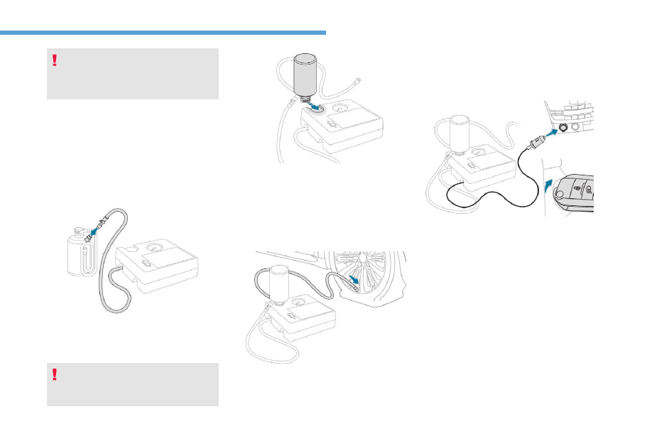
Repair procedure

F  Switch off the ignition.
F  Secure the speed limit sticker inside the 

vehicle.

F  Uncoil the pipe stowed under the 

compressor.

F  Connect the pipe from the compressor to 

the bottle of sealant.

Avoid removing any foreign bodies which 
have penetrated into the tyre.

F  Turn the sealant bottle and secure it in the 

cut-out provided on the compressor.

F  Remove the valve cap from the tyre to be 

repaired, and place it in a clean area.

F  Connect the hose from the bottle of sealant 

to the valve of the tyre to be repaired and 
tighten firmly.

F  Check that the compressor switch is at the 

"O" position.

F  Uncoil fully the electric cable, stowed under 

the compressor.

F  Connect the compressor's electrical 

connector to the vehicle's 12 V socket.

F  Switch on the ignition.

160

In the event of a breakdown

F  Start the compressor by turning the switch 

to the "l" position until the pressure of the 
tyre reaches 2.0 bars. The sealant product 
is injected under pressure into the tyre; do 
not disconnect the hose of the valve during 
this operation (risk of blowback).

If after around 5 to 7 minutes the pressure 
of 2 bars is not attained, this indicates 
that the tyre is not repairable; contact a 
PEUGEOT dealer or a qualified workshop 
for assistance.

F  Place the switch in the "O" position.
F  Remove the kit.

F  Drive immediately for approximately three 

miles (five kilometres), at reduced speed 
(between 12 and 37 mph (20 and 60 km/h)), 
to plug the puncture.

F  Stop to check the repair and the tyre 

pressure using the kit.

Take care, the sealant product is harmful 
if swallowed and causes irritation to the 
eyes.
Keep this product out of the reach of 
children.
The use-by date is marked on the bottle.
After use, do not discard the bottle by the 
roadside, take it to a PEUGEOT dealer or 
an authorised waste disposal site.
Do not forget to obtain a new bottle of 
sealant, available from a PEUGEOT 
dealer or a qualified workshop.

Checking / adjusting tyre 
pressures

You can also use the compressor, 
without injecting sealant, to check and, if 
necessary, adjust the tyre pressures

F  Remove the valve cap from the tyre and 

place it in a clean area.

F  Uncoil the pipe stowed under the 

compressor.

F  Screw the pipe onto the valve and tighten 

firmly.

8

161

In the event of a breakdown

F  Check that the compressor switch is at the 

"O" position.

F  Uncoil fully the electric cable, stowed under 

the compressor.

F  Switch on the compressor by moving the 

switch to the position "I" and adjust the 
pressure as shown on the vehicle tyre 
pressure label. To deflate: press the black 
button on the compressor hose by the valve 
connector.

F  Once the correct pressure is reached, put 

the switch to the "O" position.

F  Remove the kit then stow it.

F  Connect the compressor's electric plug to 

the vehicle's 12 V socket.

F  Switch on the ignition.

Should the pressure of one or more tyres 
be adjusted, it is necessary to reinitialise 
the under-inflation detection system.
For more information on Under-inflation 
detection
, refer to the corresponding 
section.

The tyre inflation pressures are given on 
this label.

162

In the event of a breakdown

Spare wheel

Access to the tools

List of tools

1.

Wheelbrace.
For removing the wheel trim and the 
wheel fastening bolts.

2.

Jack with integrated crank.
Used to raise the vehicle.

3.

"Bolt cover" tool.
For removing the bolt protectors (covers) 
on alloy wheels.

4.

Socket for the security bolts.
For adapting the wheelbrace to the 
special "security" bolts.

5.

Towing eye.
For more information on Towing, refer to 
the associated section.

The tools are installed in the boot under the 
floor.
To gain access:
F  open the boot,
F  lift the floor and remove it,
F  remove the carrier box containing the tools.

All of these tools are specific to your 
vehicle and may vary depending on the 
level of equipment.
Do not use them for any other purposes.

The jack must only be used to change 
a wheel with a damaged or punctured tyre.
Do not use any jack other than the one 
supplied with this vehicle.
If the vehicle does not have its original 
jack, contact a PEUGEOT dealer or a 
qualified workshop to obtain the correct 
jack for it.
The jack meets European standards, 
as defined in the Machinery Directive 
2006/42/EC.
The jack does not require any 
maintenance.

Procedure for changing a damaged wheel with 
the spare wheel using the tools provided with 
the vehicle.

Wheel with hub cap
When refitting the wheel
, refit the hub 
cap starting by placing its notch facing the 
valve and press around its edge with the 
palm of your hand.

8

163

In the event of a breakdown

Taking out the wheel

F  Unscrew the central nut.

Putting the wheel back in place

F  Put the wheel back in its housing.

F  Give the bolt a few turns to loosen it.
F  Position the fixing parts (nut and bolt) in the 

middle of the wheel.

F  Tighten fully until the central nut clicks, to 

retain the wheel correctly.

F  Put the box back in place in the centre of 

the wheel and clip it.

If there is no wheel in the well, the 
fastening device (nut and bolt) cannot be 
refitted.

Access to the spare wheel

The spare wheel is installed in the boot under 
the floor.
According to country, the spare wheel may be 
steel, alloy or of the "space-saver" type.

F  Remove the fixing parts (nut and bolt).
F  Raise the spare wheel towards you from the 

rear.

F  Take the wheel out of the boot.

164

In the event of a breakdown

Parking the vehicle
Park the vehicle where it does not block 
traffic: the ground must be level, stable 
and non-slippery.
Apply the parking brake.
Switch the ignition off.
With a manual gearbox, engage first gear 
to block the wheels.
With an electronic gearbox, place the 
lever in position R to block the wheels.
With an automatic gearbox, place the 
lever in position P to block the wheels.
Check for fixed illumination of the parking 
brake warning lamps in the instrument 
panel.
Make absolutely certain that all the 
occupants have left the vehicle and are 
waiting in a safe area.
Never go underneath a vehicle raised 
using a jack; use an axle stand.

Removing a wheel

F  Place the foot of jack 2 on the ground and 

ensure that it is directly below the front 
A or rear B jacking point provided on the 
underbody, whichever is closest to the 
wheel to be changed.

Ensure that the jack is stable on a surface 
that is not loose or slippery and positioned 
only at jacking points A or B under the 
vehicle, making sure that the jack head is 
centred at the contact point on the vehicle. 
Otherwise, there is a risk of damage to 
the vehicle and/or the jack collapsing or 
slipping – Risk of injury!

List of operations

F  Remove the bolt cover from each of the 

bolts using the tool 3 (depending on 
equipment).

F  Fit the security socket 4 on the wheelbrace 

1 to slacken the security bolt (if fitted).

F  Slacken the other bolts using wheelbrace 1 

only.

8

165

In the event of a breakdown

F  Extend the jack 2 until its head comes 

into contact with the jacking point A or B
whichever is used; the contact area or B 
on the vehicle must be correctly inserted 
into the central part of the head of the jack.

F  Raise the vehicle until there is sufficient 

space between the wheel and the ground 
to admit the spare (not punctured) wheel 
easily.

Fitting a wheel

Fitting a steel or "space-saver" spare 
wheel 
If your vehicle is fitted with alloy wheels, 
when tightening the bolts on fitting it is 
normal to notice that the washers do not 
come into contact with the steel or "space-
saver" spare wheel. The wheel is secured 
by the conical contact of each bolt.

F  Remove the bolts and store them in a clean 

place.

F  Remove the wheel.

166

In the event of a breakdown

List of operations

F  Put the wheel in place on the hub.
F  Screw in the bolts by hand to the stop.
F  Pre-tighten the security bolt using the 

wheelbrace 1 fitted with the security socket 
4 (if your vehicle has them).

F  Pre-tighten the other bolts using the 

wheelbrace 1 only.

F  Lower the vehicle again fully.
F  Fold the jack 2 and detach it.

F  Tighten the security bolt using the 

wheelbrace 1 fitted with the security socket 
4 (if your vehicle has them).

F  Tighten the other bolts using wheelbrace 1 

only.

F  Refit the bolt covers on each of the bolts 

(according to equipment).

F  Store the tools in the box.

After changing a wheel
To store the punctured wheel in the boot 
correctly, first remove the central cover.
If your vehicle has a "standard" 15-inch 
spare wheel, do not exceed 50 mph 
(80 km/h).
If your vehicle is fitted with 16 or 17-inch 
wheels, use the "space-saver" type 
spare wheel and do not exceed 50 mph 
(80 km/h).
Visit a PEUGEOT dealer or a qualified 
workshop as soon as possible to have the 
tightness of the bolts and the pressure of 
the spare wheel checked.
Have the punctured tyre examined. After 
inspection, the technician will advise you 
on whether the tyre can be repaired or if it 
must be replaced.

8

167

In the event of a breakdown

Changing a bulb

The headlamps have polycarbonate 
lenses with a protective coating:
F  do not clean them using a dry or 

abrasive cloth, nor with a detergent 
or solvent product,

F  use a sponge and soapy water or a pH 

neutral product,

F  when using a high pressure washer 

on persistent marks, do not keep the 
lance directed towards the lamps or 
their edges for too long, so as not to 
damage their protective coating and 
seals.

Changing a bulb must only be done with 
the ignition off and after the headlamp has 
been switched off for several minutes – 
Risk of serious burns!
F  Do not touch the bulb directly with your 

fingers, use a lint-free cloth.

It is essential only to use anti-ultraviolet 
(UV) type bulbs, so as not to damage the 
headlamp.
Always replace a failed bulb with a new 
bulb with the same type and specification.

In some weather conditions (e.g. low 
temperature or humidity), the presence 
of misting on the internal surface of the 
glass of the headlamps and rear lamps is 
normal; it disappears after the lamps have 
been on for a few minutes.

Front lamps

A. Model with light guide

1.

Main beam headlamps (H7-55W).

2.

Dipped beam headlamps (H7-55W).

3.

Daytime running lamps / sidelamps 
(light emitting diodes – LEDs).

4.

Direction indicators (PWY-24W).

5.

Front foglamps (directional according 
to version) (H11-55W).

B. Model without light guide

1.

Main beam headlamps (H7-55W).

2.

Dipped beam headlamps (H7-55W).

3.

Daytime running lamps / sidelamps 
(W5-5W).

4.

Direction indicators (PWY-24W).

5.

Front foglamps (directional according 
to version) (H11-55W).

168

In the event of a breakdown

C. GTi model

1.

Main beam headlamps (H7-55W).

2.

Dipped beam headlamps (H7-55W).

3.

Daytime running lamps / sidelamps 
(light emitting diodes – LEDs).

4.

Direction indicators (light-emitting 
diodes – LEDs).

5.

Front foglamps (directional according 
to version) (H11-55W).

Direction indicators

Quicker flashing of the direction indicator 
lamp (left or right) indicates that one of 
the bulbs on the corresponding side has 
failed.

F  Turn the bulb holder a quarter turn and pull 

it out.

F  Pull out the bulb and replace it.
To reassemble, proceed in reverse order.

Amber colour bulbs, such as the direction 
indicators, must be replaced by bulbs with 
identical colour and specifications.
To refit, close the protective cover very 
carefully to guarantee the leak-tightness 
of the lamp.

Dipped beam headlamps

F  Remove the protective cover by pulling on 

the tab.

F  Disconnect the bulb connector.
F  Spread the spring to release the bulb 

(model A).

F  Pull the bulb out and change it.

To reassemble, carry out these operations in 
reverse order, positioning the alignment lug at 
the bottom (model A) or at the top (model B).

8

169

In the event of a breakdown

Main beam headlamps

F  Disconnect the main headlamp connector.
F  Remove the protective cover by pulling on 

the tab.

F  Disconnect the bulb connector.
F  Pull the bulb out and change it.

To reassemble, carry out these operations in 
reverse order, positioning the alignment lug at 
the bottom.

Daytime running lamps/
sidelamps

F  Turn the bulb holder a quarter turn and pull 

it out.

F  Pull out the bulb and replace it.
To refit, carry out these operations in reverse 
order.

Daytime running lamps / 
sidelamps (light emitting diodes 
– LEDs)

For the replacement of this type of diode lamp, 
contact a PEUGEOT dealer or a qualified 
workshop.

170

In the event of a breakdown

Foglamps / directional lamps

F  Access to the front foglamp is through the 

aperture below the bumper.

F  Disconnect the bulb holder connector by 

pressing on the top of the tongue.

F  Extract the bulb holder by pressing on the 

two clips (top and bottom).

F  Replace the module.

To refit, carry out these operations in 
reverse order.
Contact a PEUGEOT dealer or a qualified 
workshop to obtain the module.
You can also contact a PEUGEOT 
dealer or a qualified workshop for the 
replacement of these bulbs.

Integrated direction indicator 
side repeaters

F  Insert a flat screwdriver between the door 

mirror glass and its base.

F  Tilt the screwdriver and use it as a lever to 

extract the glass.

F  Unclip the shell of the door mirror by 

pressing on the two fixing clips.

F  Press the central tongue and remove the 

side repeater.

F  Pull out the bulb holder and replace the 

faulty bulb.

To refit, carry out these operations in 
reverse order.
To replace this type of bulb, you can also 
contact a PEUGEOT dealer or a qualified 
workshop.

Rear lamps

1.

Brake lamps (light emitting diodes – 
LEDs).

2.

Reversing lamps (P21W).

3.

Direction indicators (PY21W amber)

4.

Sidelamps (light emitting diodes – 
LEDs).

8

171

In the event of a breakdown

5.

Foglamp (P21W).

Light-emitting diodes – LEDs

For replacement, contact a PEUGEOT 
dealer or a qualified workshop.

Reversing lamps and direction 
indicators

These two bulbs are changed from inside the 
boot:

F  Open the boot.

F  Remove the access grille from the 

corresponding side trim panel.

F  Unscrew and remove the nut.
F  Disconnect the lamp unit connector.
F  Unclip the lamp unit and carefully extract it 

pulling straight towards you.

F  Press the four tabs and remove the bulb 

holder.

F  Turn the bulb a quarter turn, pull it out and 

fit a new bulb.

To reassemble, proceed in reverse order.
Make sure to engage the lamp unit in its guides 
while keeping it in line with the vehicle.
Tighten sufficiently to ensure sealing, but 
without damaging the lamp.

Third brake lamp

F  Unscrew the fixing pins on each side of the 

lamp, without removing them completely.

F  Push on the screws to unclip the lamp unit.
F  Disconnect the lamp unit connector.
F  Remove the lamp unit from the outside.
F  Turn the bulb holder corresponding to the 

faulty lamp a quarter turn and pull it out.

F  Pull the bulb out and change it.
To reassemble, proceed in reverse order.

172

In the event of a breakdown

Licence plate lamps

For easier removal, perform this procedure with 
the tailgate half open.
F  Insert a thin screwdriver into the cut-out 

located outside the lens.

F  Push it outwards.
F  Remove the lens.
F  Change the faulty bulb.
To refit, press on the lens to clip it in place.

Foglamp

For access, pass your hand under the bumper.
F  Turn the bulb holder a quarter turn and pull 

it out.

F  Disconnect the lamp unit connector.
F  Pull the bulb out and change it.
To refit, carry out these operations in reverse 
order.
To replace this type of bulb, you can also 
contact a PEUGEOT dealer or a qualified 
workshop.

Changing a fuse

Access to the tools

The extraction tweezers are fitted to the back 
of the dashboard fusebox cover or glovebox.

Dashboard

F  Unclip the cover by pulling at the top left, 

then right.

F  Disengage the cover completely and turn it 

over.

F  Remove the carrier on which the tweezers 

are fitted.

8

173

In the event of a breakdown

Glove box

F  Open the glove box lid.
F  Unclip the fusebox cover by pulling at the 

top right.

F  Disengage the cover completely and turn it 

over.

F  Remove the carrier on which the tweezers 

are fitted.

Before changing a fuse, it is necessary that:
F  the vehicle must be stationary with the 

ignition off,

F  switch off all electrical consumers,
F  the defective fuse must be identified using 

the allocation tables and the diagrams in the 
following pages.

To work on a fuse, you must:
F  use the special tweezers to extract the fuse 

from its housing and check the condition of 
its filament,

F  always replace the defective fuse with a 

fuse of the same rating (same colour); using 
a different rating could cause a malfunction 
(risk of fire).

If the fault recurs after replacing a fuse, have 
the electrical system checked by a PEUGEOT 
dealer or a qualified workshop.

The fuse allocation tables and 
corresponding diagrams are available on 
the website:
http://public.servicebox.peugeot.com/ddb/
You can go to a PEUGEOT dealer or a 
qualified workshop.

OK

Failed

Tweezers

Professional repairers: for full information 
on the fuses and relays, consult the wiring 
information and diagrams available at a 
PEUGEOT dealer.

The replacement of a fuse not shown in 
the allocation tables opposite may cause 
a serious malfunction of your vehicle. 
Contact a PEUGEOT dealer or a qualified 
workshop.

174

In the event of a breakdown

Installing electrical 
accessories

Your vehicle's electrical system is 
designed to operate with standard or 
optional equipment.
Before installing other electrical 
equipment or accessories on your vehicle, 
contact a PEUGEOT dealer or a qualified 
workshop.

PEUGEOT accepts no responsibility for 
the cost incurred in repairing your vehicle 
or for rectifying malfunctions resulting 
from the installation of accessories 
not supplied and not recommended by 
PEUGEOT and not installed in accordance 
with specifications, in particular when the 
combined power consumption of all of the 
additional equipment connected exceeds 
10 milliamperes.

On the left

Fuse no.

Rating

Functions

F1 (GPL)

10 A

Ignition + (positive).

F2

5 A

Exterior mirrors, headlamps, diagnostic socket.

F9

5 A

Alarm.

F10

5 A

Independent telematic unit, trailer interface unit.

F11

5 A

Electrochrome interior rear-view mirror, additional 
heating.

F13

5 A

Hi-Fi amplifier, parking sensors.

F16

15 A

Front 12 V socket.

F17

15 A

Audio system, after-market audio system.

F18

20 A

Touch screen.


Content   ..  9  10  11  12   ..