Nissan Qashqai (2007-2010). Manual - part 904
 

  Index      Nissan     Nissan Qashqai - service and repair manual 2007 - 2010 year


Search            copyright infringement  


Content   ..  902  903  904  905   ..


Nissan Qashqai (2007-2010). Manual - part 904


HA-186

< ON-VEHICLE MAINTENANCE >

[MANUAL AIR CONDITIONER (K9K)]

ELECTRICAL LEAK DETECTOR

ELECTRICAL LEAK DETECTOR

Inspection

INFOID:0000000001098286

PRECAUTIONS FOR HANDLING LEAK DETECTOR

When performing a refrigerant leak check, use an electrical leak
detector (SST: J-41995) or equivalent. Ensure that the instrument is
calibrated and set properly per the operating manuals.
The leak detector is a delicate device. In order to use the leak detec-
tor properly, read the operating instructions and perform any speci-
fied maintenance.

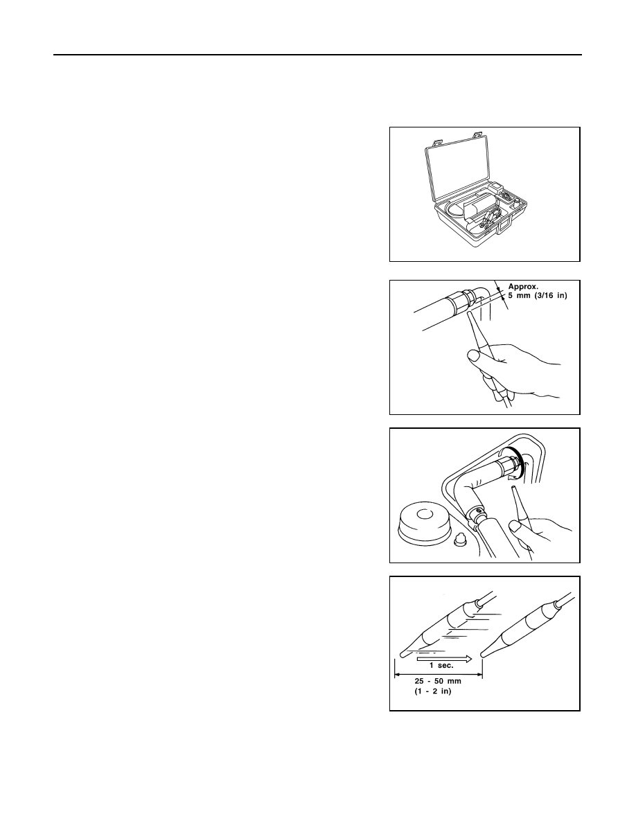
1.

Position probe approximately 5 mm (3/16 in) away from point to
be checked.

2.

When testing, circle each fitting completely with probe.

3.

Move probe along component approximately 25 to 50 mm (1 to
2 in)/sec.

CHECKING PROCEDURE

To prevent inaccurate or false readings, make sure there is no refrigerant vapor, shop chemicals, or cigarette
smoke in the vicinity of the vehicle. Perform the leak test in calm area (low air/wind movement) so that the
leaking refrigerant is not dispersed.

1.

Stop the engine.

AHA281A

SHA707EA

SHA706E

SHA708EA

ELECTRICAL LEAK DETECTOR

HA-187

< ON-VEHICLE MAINTENANCE >

[MANUAL AIR CONDITIONER (K9K)]

C

D

E

F

G

H

J

K

L

M

A

B

HA

N

O

P

2.

Connect a suitable A/C manifold gauge set (SST: J-39183) to the A/C service valves.

3.

Check if the A/C refrigerant pressure is at least 345 kPa (3.52 kg/cm

2

, 50 psi) above 16

°

C (61

°

F). If less

than specification, recover/evacuate and recharge the system with the specified amount of refrigerant.
NOTE:
At temperatures below 16

°

C (61

°

F), leaks may not be detected since the system may not reach 345 kPa

(3.52 kg/cm

2

, 50 psi).

4.

Perform the leak test from the high-pressure side (compressor discharge a to evaporator inlet j) to the
low-pressure side (evaporator drain hose k to shaft seal p). Perform a leak check for the following areas
carefully. Clean the component to be checked and move the leak detected probe completely around the
connection/component.

Compressor
Check the fitting of high- and low-pressure flexible hoses, relief valve and shaft seal.
Condenser
Check the fitting of condenser pipe assembly, high-pressure flexible hose and pipe.
Liquid tank
Check the fitting of radiator & condenser assembly and refrigerant pressure sensor.
Service valves
Check all around the service valves. Ensure service valve caps are secured on the service valves (to pre-
vent leaks).
NOTE:

1.

Heater sealing

2.

Expansion valve

3.

Low pressure pipe 1 and high pressure 
pipe 2 assembly

4.

Evaporator

5.

O-ring

6.

Connector pipe fixing bolt

7.

High pressure pipe 1

8.

Condenser assembly

9.

Fixing bolt

10.

Compressor

11.

Heater & cooling unit assembly

12. Heater & blower unit assembly

13.

Refrigerant pressure sensor

14.

Liquid tank

15. Liquid tank fixing screw

16.

Low pressure flexible hose

17.

Fixing bolt

18. Pipes fixing clip

19.

Low & high pressure pipe bracket

20.

Liquid tank fixing bracket

21. High pressure flexible hose

22.

Low pressure pipe 2

23.

Low pressure pipe fixing clamp as-
sembly

24. Pipe mantening clip

E1KIA0063GB

HA-188

< ON-VEHICLE MAINTENANCE >

[MANUAL AIR CONDITIONER (K9K)]

ELECTRICAL LEAK DETECTOR

After removing A/C manifold gauge set from service valves, wipe any residue from valves to prevent any
false readings by leak detector.
Cooling unit (Evaporator)
With engine OFF, turn blower fan on “High” for at least 15 seconds to dissipate any refrigerant trace in the
cooling unit. Wait a minimum of 10 minutes accumulation time (refer to the manufacturer’s recommended
procedure for actual wait time) before inserting the leak detector probe into the drain hose.
Keep the probe inserted for at least 10 seconds. Use caution not to contaminate the probe tip with water
or dirt that may be in the drain hose.

5.

If a leak detector detects a leak, verify at least once by blowing compressed air into area of suspected
leak, then repeat check as outlined above.

6.

Do not stop when one leak is found. Continue to check for additional leaks at all system components.
If no leaks are found, perform steps 7 - 10.

7.

Start the engine.

8.

Set the A/C control as follows;

a.

A/C switch: ON

b.

MODE door position: VENT (Ventilation)

c.

Intake door position: Recirculation

d.

Temperature setting: Max. cold

e.

Fan speed: High

9.

Run engine at 1,500 rpm for at least 2 minutes.

10. Stop the engine and perform leak check again following steps 4

through 6 above.
Refrigerant leaks should be checked immediately after stopping
the engine. Begin with the leak detector at the compressor. The
pressure on the high-pressure side will gradually drop after
refrigerant circulation stops and pressure on the low-pressure
side will gradually rise, as shown in the graph. Some leaks are
more easily detected when pressure is high.

11. Before connecting recovery/recycling recharging equipment to vehicle, check recovery/recycling recharg-

ing equipment gauges. No refrigerant pressure should be displayed. If pressure is displayed, recover
refrigerant from equipment lines and then check refrigerant purity.

12. Confirm refrigerant purity in supply tank using recovery/recycling recharging equipment and refrigerant

identifier.

13. Confirm refrigerant purity in vehicle A/C system using recovery/recycling recharging equipment and refrig-

erant identifier.

14. Discharge A/C system using approved refrigerant recovery equipment. Repair the leaking fitting or com-

ponent if necessary.

15. Evacuate and recharge A/C system and perform the leak test to confirm no refrigerant leaks.

16. Perform A/C performance test to ensure system works properly.

SHA839E

REFRIGERATION SYSTEM

HA-189

< ON-VEHICLE REPAIR >

[MANUAL AIR CONDITIONER (K9K)]

C

D

E

F

G

H

J

K

L

M

A

B

HA

N

O

P

ON-VEHICLE REPAIR

REFRIGERATION SYSTEM

Exploded View

INFOID:0000000001098287

Refer to 

HA-171, "Refrigerant Connection"

.

Inspection After Installation

INFOID:0000000001098288

SETTING OF SERVICE TOOLS AND EQUIPMENT

Discharging Refrigerant

WARNING:

Avoid breathing A/C refrigerant and lubricant vapor or mist. Exposure may irritate eyes, nose and
throat. Remove HFC-134a (R-134a) from A/C system using certified service equipment meeting
requirements of SAE J-2210 [HFC-134a (R-134a) recycling equipment] or J-2209 [HFC-134a (R-134a)
recovery equipment]. If accidental system discharge occurs, ventilate work area before resuming ser-
vice. Additional health and safety information may be obtained from refrigerant and lubricant manu-
facturers.

1.

Heater sealing

2.

Expansion valve

3.

Low pressure pipe 1 and high pres-
sure pipe 2 assembly

4.

Evaporator

5.

O-ring

6.

Connector pipe fixing bolt

7.

High pressure pipe 1

8.

Condenser assembly

9.

Fixing bolt

10. Compressor

11.

Heater & cooling unit assembly

12. Heater & blower unit assembly

13. Refrigerant pressure sensor

14. Liquid tank

15. Liquid tank fixing screw

16. Low pressure flexible hose

17. Fixing bolt

18. Pipes fixing clip

19. Low & high pressure pipe bracket

20. Liquid tank fixing bracket

21. High pressure flexible hose

22. Low pressure pipe 2

23. Low pressure pipe fixing clamp as-

sembly

24. Pipe mantening clip

E1KIA0063GB


Content   ..  902  903  904  905   ..