Nissan Qashqai (2007-2010). Manual - part 574
 

  Index      Nissan     Nissan Qashqai - service and repair manual 2007 - 2010 year


Search            copyright infringement  


Content   ..  572  573  574  575   ..


Nissan Qashqai (2007-2010). Manual - part 574


P0715 INPUT SPEED SENSOR (PRI SPEED SENSOR)

TM-231

< COMPONENT DIAGNOSIS >

[CVT: RE0F10A]

C

E

F

G

H

I

J

K

L

M

A

B

TM

N

O

P

P0715 INPUT SPEED SENSOR (PRI SPEED SENSOR)

Description

INFOID:0000000000988661

The input speed sensor (primary speed sensor) detects the primary pulley revolution speed and sends a sig-
nal to the TCM.

DTC Logic

INFOID:0000000000988662

DTC DETECTION LOGIC

DTC CONFIRMATION PROCEDURE

CAUTION:

Always drive vehicle at a safe speed.
NOTE:
If “DTC CONFIRMATION PROCEDURE” has been previously performed, always turn ignition switch
OFF and wait at least 10 seconds before performing the next test.
After the repair, perform the following procedure to confirm the malfunction is eliminated.

1.

CHECK DTC DETECTION

With CONSULT-III

1.

Turn ignition switch ON.

2.

Select “DATA MONITOR”.

3.

Start engine and maintain the following conditions for at least 5 consecutive seconds.

With GST

Follow the procedure “With CONSULT-III”.

Is “P0715 INPUT SPD SEN/CIRC” detected?

YES

>> Go to 

TM-231, "Diagnosis Procedure"

.

NO

>> Check intermittent incident. Refer to 

GI-39, "Intermittent Incident"

.

Diagnosis Procedure

INFOID:0000000000988663

1.

 CHECK PRIMARY SPEED SENSOR

With CONSULT-III

1.

Start engine.

2.

Check power supply to input speed sensor (primary speed sensor) by voltage between TCM connector
terminals.

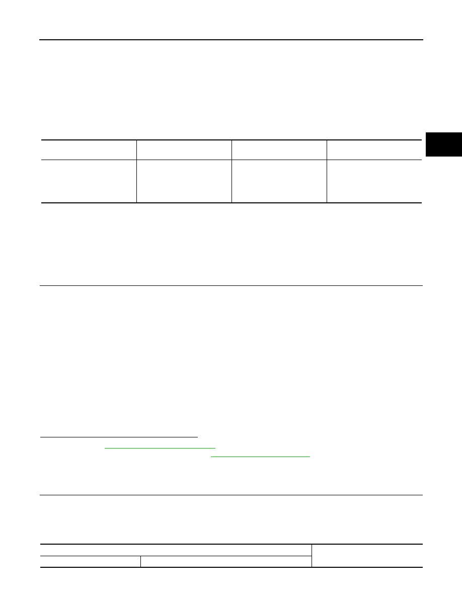
DTC

Item

(CONSULT-III screen term)

Malfunction is detected when...

Possible cause

P0715

INPUT SPD SEN/CIRC

• Input speed sensor (primary 

speed sensor) signal is not 
input due to an open circuit.

• An unexpected signal is input 

when vehicle is being driven.

• Harness or connectors

(Sensor circuit is open or 
shorted.)

• Input speed sensor (Primary 

speed sensor)

VEHICLE SPEED

: 10 km/h (6 MPH) or more

ACC PEDAL OPEN

: More than 1.0/8

RANGE

: “D” position

ENG SPEED

: 450 rpm or more

Driving location

: Driving the vehicle uphill (in-
creased engine load) will help 
maintain the driving conditions 
required for this test.

TCM connector

Voltage (Approx.) 

Connector

Terminal

TM-232

< COMPONENT DIAGNOSIS >

[CVT: RE0F10A]

P0715 INPUT SPEED SENSOR (PRI SPEED SENSOR)

3.

If OK, check the pulse when vehicle cruises.

Is the inspection result normal?

YES

>> GO TO 7.

NO

>> GO TO 2.

2.

 CHECK POWER AND SENSOR GROUND

1.

Turn ignition switch OFF.

2.

Disconnect the input speed sensor (primary speed sensor) harness connector.

3.

Turn ignition switch ON.

4.

Check voltage between input speed sensor (primary speed sensor) harness connector terminals.

5.

Check voltage between input speed sensor (primary speed sensor) harness connector terminal and
ground.

6.

If OK, check harness for short to ground and short to power.

7.

Reinstall any part removed.

Is the inspection result normal?

YES

>> GO TO 3.

NO - 1 >> Battery voltage is not supplied between terminals 1 and 3, terminal 3 and ground: GO TO 4.
NO - 2 >> Battery voltage is not supplied between terminals 1 and 3 only: GO TO 5.

3.

 CHECK HARNESS BETWEEN TCM AND INPUT SPEED SENSOR (PRIMARY SPEED SENSOR)

1.

Turn ignition switch OFF.

2.

Disconnect TCM connector.

3.

Check continuity between TCM connector terminal and input speed sensor (primary speed sensor) har-
ness connector terminal.

4.

If OK, check harness for short to ground and short to power.

5.

Reinstall any part removed.

Is the inspection result normal?

YES

>> GO TO 6.

NO

>> Repair open circuit or short to ground or short to power in harness or connectors.

4.

 CHECK HARNESS BETWEEN TCM AND INPUT SPEED SENSOR (PRIMARY SPEED SENSOR) (POW-

F25

25

46

Battery voltage

48

TCM connector

Condition

Data (Approx.) 

Connector

Terminal

F25

33

When running at 20 km/h (12 MPH) in “M

1

” position, use the CONSULT-III pulse 

frequency measuring function.

CAUTION:

Connect the data link connector to the vehicle-side diagnosis connector.

800 Hz

Input speed sensor (primary speed sensor) harness connector

Voltage (Approx.) 

Connector

Terminal

F55

1

3

Battery voltage

Input speed sensor (primary speed sensor) harness connec-

tor

Ground

Voltage (Approx.) 

Connector

Terminal

F55

3

Battery voltage

TCM connector

Input speed sensor (primary speed sensor) harness connector

Continuity

Connector

Terminal

Connector

Terminal

F25

33

F55

2

Existed

P0715 INPUT SPEED SENSOR (PRI SPEED SENSOR)

TM-233

< COMPONENT DIAGNOSIS >

[CVT: RE0F10A]

C

E

F

G

H

I

J

K

L

M

A

B

TM

N

O

P

ER)

1.

Turn ignition switch OFF.

2.

Disconnect TCM connector.

3.

Check continuity between TCM connector terminals and input speed sensor (primary speed sensor) har-
ness connector terminal.

4.

If OK, check harness for short to ground and short to power.

5.

Reinstall any part removed.

Is the inspection result normal?

YES

>> 10 A fuse (No. 55, located in the IPDM E/R) or ignition switch are malfunctioning. 

NO

>> Repair open circuit or short to ground or short to power in harness or connectors.

5.

 CHECK HARNESS BETWEEN TCM AND INPUT SPEED SENSOR (PRIMARY SPEED SENSOR) (SEN-

SOR GROUND)

1.

Turn ignition switch OFF.

2.

Disconnect TCM connector.

3.

Check continuity between TCM connector terminal and input speed sensor (primary speed sensor) har-
ness connector terminal.

4.

If OK, check harness for short to ground and short to power.

5.

Reinstall any part removed.

Is the inspection result normal?

YES

>> GO TO 6.

NO

>> Repair open circuit or short to ground or short to power in harness or connectors.

6.

 CHECK THE TCM SHORT

Replace same type TCM, perform self-diagnosis check. Erase self-diagnostic results and then drive the vehi-
cle [more than 10 km/h (6 MPH)], perform self-diagnosis check. Refer to 

TM-231, "DTC Logic"

.

 Is “P0715 INPUT SPD SEN/CIRC” detected again?

YES

>> Replace the primary speed sensor. Refer to

TM-339, "Exploded View"

.

NO

>> Replace the TCM. Refer to 

TM-325, "Exploded View"

.

7.

CHECK TCM

Check TCM input/output signals. Refer to 

TM-285, "Reference Value"

.

Is the inspection result normal?

YES

>> Check intermittent incident. Refer to 

GI-39, "Intermittent Incident"

.

NO

>> Replace TCM. Refer to 

TM-325, "Exploded View"

.

IPDM E/R

Input speed sensor (primary speed sensor) harness connector

Continuity

Connector

Terminal

Connector

Terminal

E11

16

F55

3

Existed

TCM connector

Input speed sensor (primary speed sensor) harness connector

Continuity

Connector

Terminal

Connector

Terminal

F25

25

F55

1

Existed

TM-234

< COMPONENT DIAGNOSIS >

[CVT: RE0F10A]

P0720 VEHICLE SPEED SENSOR CVT (SECONDARY SPEED SENSOR)

P0720 VEHICLE SPEED SENSOR CVT (SECONDARY SPEED SENSOR)

Description

INFOID:0000000000988664

The vehicle speed sensor CVT [output speed sensor (secondary speed sensor)] detects the revolution of the
CVT output shaft and emits a pulse signal. The pulse signal is sent to the TCM, which converts it into vehicle
speed.

DTC Logic

INFOID:0000000000988665

DTC DETECTION LOGIC

DTC CONFIRMATION PROCEDURE

CAUTION:

Always drive vehicle at a safe speed.
NOTE:
If “DTC CONFIRMATION PROCEDURE” has been previously performed, always turn ignition switch
OFF and wait at least 10 seconds before performing the next test.
After the repair, perform the following procedure to confirm the malfunction is eliminated.

1.

CHECK DTC DETECTION

With CONSULT-III

1.

Turn ignition switch ON.

2.

Select “DATA MONITOR”.

3.

Start engine and maintain the following conditions for at least 12 consecutive seconds.

4.

If DTC is detected, 

With GST

Follow the procedure “With CONSULT-III”.

Is “P0720 VEH SPD SEN/CIR AT” detected?

YES

>> Go to 

TM-234, "Diagnosis Procedure"

.

NO

>> Check intermittent incident. Refer to 

GI-39, "Intermittent Incident"

.

Diagnosis Procedure

INFOID:0000000000988666

1.

 CHECK SECONDARY SPEED SENSOR

With CONSULT-III

1.

Start engine.

2.

Check power supply to output speed sensor (secondary speed sensor) by voltage between TCM connec-
tor terminals.

DTC

Item

(CONSULT-III screen term)

Malfunction is detected when...

Possible cause

P0720

VEH SPD SEN/CIR AT

• Signal from vehicle speed 

sensor CVT [Output speed 
sensor (Secondary speed 
sensor)] not input due to 
open or short circuit.

• Unexpected signal input dur-

ing running.

• Harness or connectors

(Sensor circuit is open or 
shorted.)

• Output speed sensor (Sec-

ondary speed sensor)

ACC PEDAL OPEN

: More than 1.0/8

RANGE

: “D” position

Driving location

: Driving the vehicle uphill (in-
creased engine load) will help 
maintain the driving conditions 
required for this test.


Content   ..  572  573  574  575   ..