Nissan Qashqai (2007-2010). Manual - part 571
 

  Index      Nissan     Nissan Qashqai - service and repair manual 2007 - 2010 year


Search            copyright infringement  


Content   ..  569  570  571  572   ..


Nissan Qashqai (2007-2010). Manual - part 571


DIAGNOSIS SYSTEM (TCM)

TM-219

< FUNCTION DIAGNOSIS >

[CVT: RE0F10A]

C

E

F

G

H

I

J

K

L

M

A

B

TM

N

O

P

 X: Standard, —: Not applicable, 

: Option

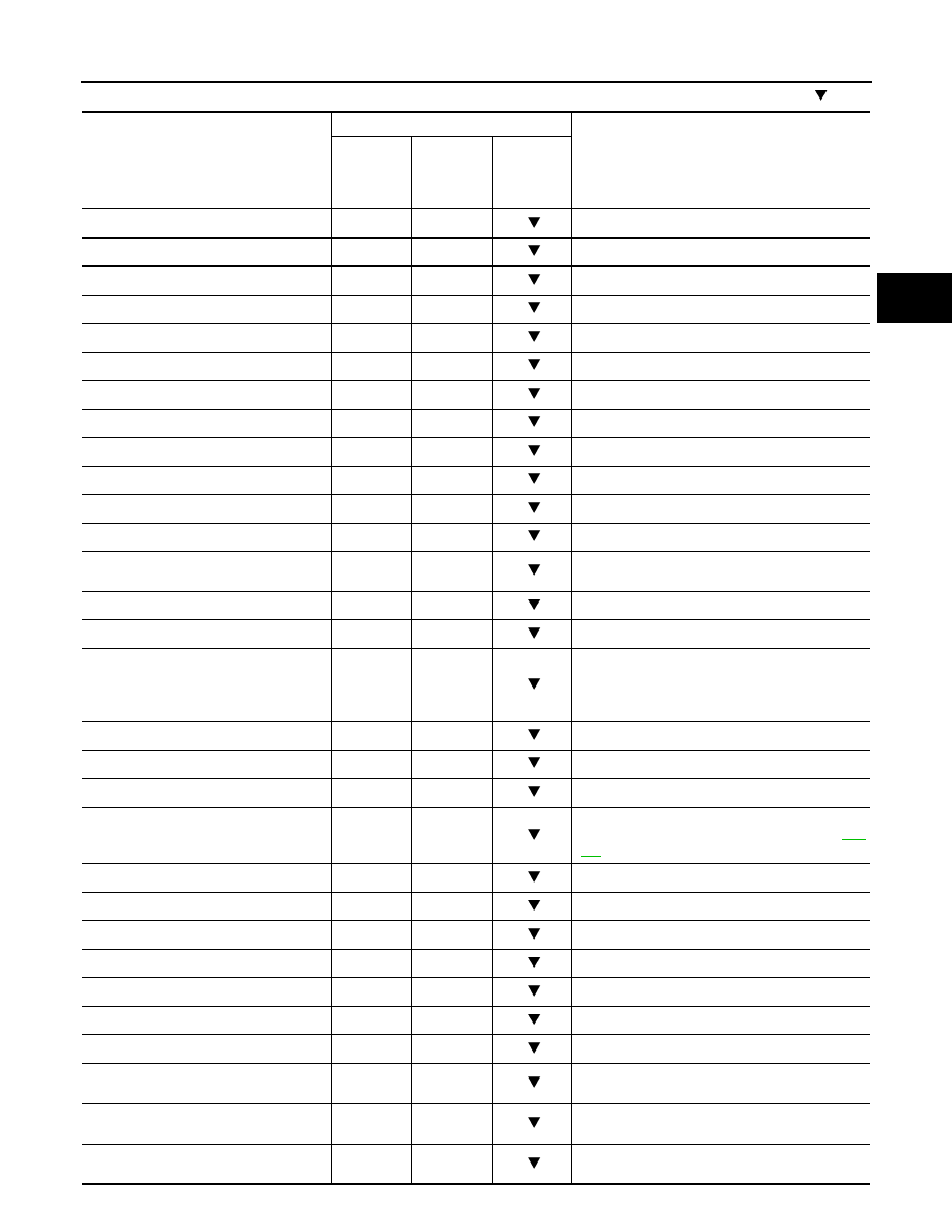
Monitored item (Unit)

Monitor item selection

Remarks

 ECU IN-

PUT SIG-

NALS

MAIN SIG-

NALS

SELEC-

TION 

FROM 
MENU

VSP SENSOR (km/h)

X

Output speed sensor (secondary speed sensor)

ESTM VSP SIG (km/h)

X

PRI SPEED SEN (rpm) 

X

ENG SPEED SIG (rpm) 

X

SEC HYDR SEN (V)

X

PRI HYDR SEN (V)

X

ATF TEMP SEN (V)

X

CVT fluid temperature sensor

VIGN SEN (V)

 X

VEHICLE SPEED (km/h)

X

Vehicle speed recognized by the TCM.

PRI SPEED (rpm)

X

Primary pulley speed

SEC SPEED (rpm)

Secondary pulley speed

ENG SPEED (rpm) 

X

SLIP REV (rpm)

X

Difference between engine speed and primary 
pulley speed.

GEAR RATIO

X

G SPEED (G)

ACC PEDAL OPEN (0.0/8)

X

X

Degree of opening for accelerator recognized by 
the TCM.
For fail-safe operation, the specific value used for 
control is displayed.

TRQ RTO

SEC PRESS (MPa)

X

PRI PRESS (MPa)

X

ATFTEMP COUNT

X

Means CVT fluid temperature. Actual oil temper-
ature (

°

 numeric value is converted. Refer to 

TM-

311

DSR REV (rpm)

DGEAR RATIO

DSTM STEP (step)

STM STEP (step)

X

LU PRS (MPa)

LINE PRS (MPa)

TGT SEC PRESS (MPa)

ISOLT1 (A)

X

Torque converter clutch solenoid valve output 
current

ISOLT2 (A)

X

Pressure control solenoid valve A (line pressure 
solenoid valve) output current

ISOLT3 (A)

X

Pressure control solenoid valve B (secondary 
pressure solenoid valve) output current

TM-220

< FUNCTION DIAGNOSIS >

[CVT: RE0F10A]

DIAGNOSIS SYSTEM (TCM)

SOLMON1 (A)

X

X

Torque converter clutch solenoid valve monitor 
current

SOLMON2 (A)

X

X

Pressure control solenoid valve A (line pressure 
solenoid valve) monitor current

SOLMON3 (A)

X

X

Pressure control solenoid valve B (secondary 
pressure solenoid valve) monitor current

P POSITION SW (ON/OFF)

X

R POSITION SW (ON/OFF)

X

N POSITION SW (ON/OFF)

X

D POSITION SW (ON/OFF)

X

L POSITION SW (ON/OFF)

X

BRAKE SW (ON/OFF)

X

X

Stop lamp switch (Signal input with CAN commu-
nications)

FULL SW (ON/OFF)

X

X

Signal input with CAN communications

IDLE SW (ON/OFF)

X

X

SPORT MODE SW (ON/OFF)

X

X

Not mounted but displayed.

STRDWNSW (ON/OFF)

X

STRUPSW (ON/OFF)

X

DOWNLVR (ON/OFF)

X

UPLVR (ON/OFF)

X

NONMMODE (ON/OFF)

X

MMODE (ON/OFF)

X

INDLRNG (ON/OFF)

INDDRNG (ON/OFF)

“D” position indicator output

INDNRNG (ON/OFF)

“N” position indicator output

INDRRNG (ON/OFF)

“R” position indicator output

INDPRNG (ON/OFF)

“P” position indicator output

CVT LAMP (ON/OFF)

SPORT MODE IND (ON/OFF)

MMODE IND (ON/OFF)

SMCOIL D (ON/OFF)

Step motor coil “D” energizing status

SMCOIL C (ON/OFF)

Step motor coil “C” energizing status

SMCOIL B (ON/OFF)

Step motor coil “B” energizing status

SMCOIL A (ON/OFF)

Step motor coil “A” energizing status

LUSEL SOL OUT (ON/OFF)

LUSEL SOL MON (ON/OFF)

VDC ON (ON/OFF)

X

ESP (Electronic Stability Program System)

Monitored item (Unit)

Monitor item selection

Remarks

 ECU IN-

PUT SIG-

NALS

MAIN SIG-

NALS

SELEC-

TION 

FROM 
MENU

DIAGNOSIS SYSTEM (TCM)

TM-221

< FUNCTION DIAGNOSIS >

[CVT: RE0F10A]

C

E

F

G

H

I

J

K

L

M

A

B

TM

N

O

P

Diagnostic Tool Function

INFOID:0000000000988628

 OBD SELF-DIAGNOSTIC PROCEDURE (WITH GST)

Refer to 

EC-726, "Diagnosis Tool Function"

 (WITH EURO-OBD).

TCS ON (ON/OFF)

X

ABS ON (ON/OFF)

X

ACC ON (ON/OFF)

X

Not mounted but displayed.

RANGE

X

Indicates position is recognized by TCM. Indi-
cates a specific value required for control when 
fail-safe function is activated.

M GEAR POS

X

Voltage (V) 

Displays the value measured by the voltage 
probe.

Frequency (Hz)

The value measured by the pulse probe is dis-
played.

DUTY-HI (high) (%)

DUTY-LOW (low) (%)

PLS WIDTH-HI (ms) 

PLS WIDTH-LOW (ms) 

Monitored item (Unit)

Monitor item selection

Remarks

 ECU IN-

PUT SIG-

NALS

MAIN SIG-

NALS

SELEC-

TION 

FROM 
MENU

TM-222

< COMPONENT DIAGNOSIS >

[CVT: RE0F10A]

U1000 CAN COMM CIRCUIT

COMPONENT DIAGNOSIS

U1000 CAN COMM CIRCUIT

Description

INFOID:0000000000988643

CAN (Controller Area Network) is a serial communication line for real time application. It is an on-vehicle mul-
tiplex communication line with high data communication speed and excellent malfunction detection ability.
Many electronic control units are equipped onto a vehicle, and each control unit shares information and links
with other control units during operation (not independent). In CAN communication, control units are con-
nected with 2 communication lines (CAN-H and CAN-L) allowing a high rate of information transmission with
less wiring. Each control unit transmits/receives data but selectively reads required data only.

DTC Logic

INFOID:0000000000988644

DTC DETECTION LOGIC

DTC CONFIRMATION PROCEDURE

NOTE:
If “DTC CONFIRMATION PROCEDURE” has been previously performed, always turn ignition switch
OFF and wait at least 10 seconds before performing the next test.
After the repair, perform the following procedure to confirm the malfunction is eliminated.

1.

CHECK DTC DETECTION

With CONSULT-III

1.

Turn ignition switch ON.

2.

Start engine and wait for at least 6 seconds.

3.

Perform “SELF-DIAG RESULTS”. Refer to 

TM-216, "CONSULT-III Function (TRANSMISSION)"

.

 With GST

Follow the procedure “With CONSULT-III”.
Is “U1000 CAN COMM CIRCUIT” detected?

YES

>> Go to 

TM-222, "Diagnosis Procedure"

.

NO

>> Check intermittent incident. Refer to 

GI-39, "Intermittent Incident"

.

Diagnosis Procedure

INFOID:0000000000988645

1.

CHECK CAN COMMUNICATION CIRCUIT

With CONSULT-III

1.

Turn ignition switch ON and start engine.

2.

Select “SELF-DIAG RESULTS”.

Is any malfunction of the “U1000 CAN COMM CIRCUIT” indicated?

YES

>> Go to LAN section. Refer to 

LAN-55, "CAN System Specification Chart"

.

NO

>> Check intermittent incident. Refer to 

GI-39, "Intermittent Incident"

.

DTC

Item

 (CONSULT-III screen term)

Malfunction is detected when...

Possible cause

U1000

CAN COMM CIRCUIT

When TCM is not transmitting 
or receiving CAN communica-
tion signal for 2 seconds or 
more.

Harness or connectors
(CAN communication line is 
open or shorted.)


Content   ..  569  570  571  572   ..