Nissan Qashqai (2007-2010). Manual - part 569
SHIFT LOCK SYSTEM
TM-211
< FUNCTION DIAGNOSIS >
[CVT: RE0F10A]
C
E
F
G
H
I
J
K
L
M
A
B
TM
N
O
P
SHIFT LOCK SYSTEM
System Description
INFOID:0000000000914573
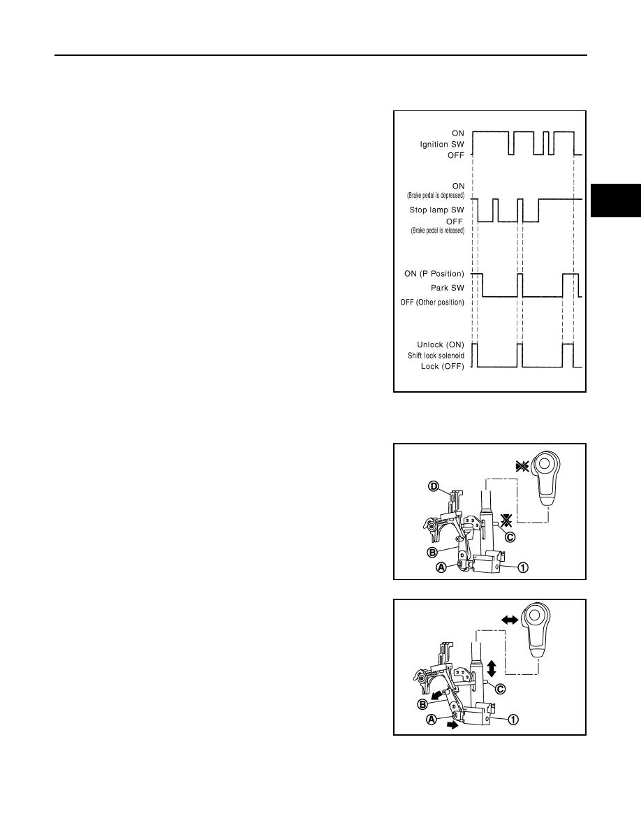
It is designed so that it cannot be shifted from the P position unless
the brake pedal is depressed while the ignition switch is set to ON.
The shift lock is unlocked by turning the shift lock solenoid ON when
the ignition switch is set to ON, the park switch is turned ON (selec-
tor lever is in P position), and the stop lamp switch is turned ON
(brake pedal is depressed) as shown in the operation chart in the fig-
ure. Therefore, the shift lock solenoid receives no ON signal and the
shift lock remains locked if all of the above conditions are not ful-
filled. (However, selector operation is allowed if the shift lock release
button is pressed.)
SHIFT LOCK OPERATION at P POSITION
When Brake Pedal Is Not Depressed (No Selector Operation Allowed)
The shift lock solenoid (1) is turned OFF (not energized) and the
solenoid rod (A) is extended with the spring when the brake pedal is
not depressed (no selector operation allowed) with the ignition
switch ON.
The connecting lock lever (B) is located at the position shown in the
figure when the solenoid rod is extended. It prevents the movement
of the detent rod (C). The selector lever cannot be shifted from the P
position for this reason. However, the lock lever is forcibly moved to
the direction opposite to that of the arrow when the shift lock release
button (D) is pressed. Selector operation can be performed.
When Brake Pedal Is Depressed (Shift Operation Allowed)
The shift lock solenoid (1) is turned ON (energized) when the brake
pedal is depressed with the ignition switch ON. The solenoid rod (A)
is compressed with the electromagnetic force. The connecting lock
lever (B) rotates when the solenoid is compressed. Therefore, the
detent rod (C) can be moved. The selector lever can be shifted to
other positions for this reason.
P POSITION HOLD MECHANISM (IGNITION SWITCH LOCK)
JPDIA0183GB
JPDIA0110ZZ
JPDIA0111ZZ