Nissan Qashqai (2007-2010). Manual - part 501
 

  Index      Nissan     Nissan Qashqai - service and repair manual 2007 - 2010 year


Search            copyright infringement  


Content   ..  499  500  501  502   ..


Nissan Qashqai (2007-2010). Manual - part 501


EX-10

< ON-VEHICLE REPAIR >

[MR20DE]

EXHAUST SYSTEM

ON-VEHICLE REPAIR

EXHAUST SYSTEM

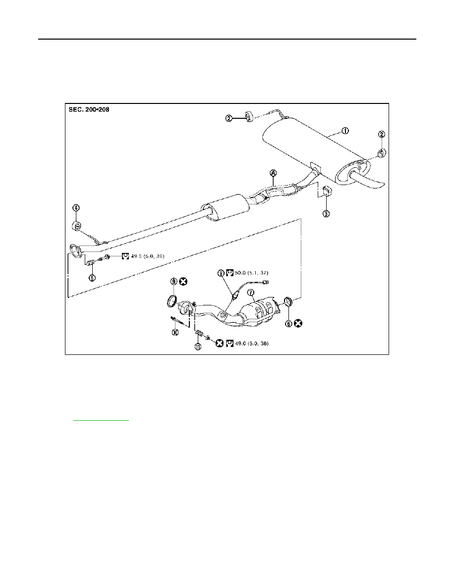
Exploded View

INFOID:0000000000905825

Removal and Installation

INFOID:0000000000905826

REMOVAL

• Disconnect each joint and mounting.
• Remove heated oxygen sensor 2 with following procedure.

1.

Main muffler

2.

Mounting rubber

3.

Mounting rubber

4.

Mounting rubber

5.

Spring

6.

Seal bearing

7.

Exhaust front tube

8.

Heated oxygen sensor 2

9.

Seal bearing

10. Stud bolt

11. Spring

A.

Insulator (4WD models)

Refer to 

GI-4, "Components"

 for symbols in the figure.

JPBIA0295GB

EXHAUST SYSTEM

EX-11

< ON-VEHICLE REPAIR >

[MR20DE]

C

D

E

F

G

H

I

J

K

L

M

A

EX

N

P

O

- Using heated oxygen sensor wrench [SST: KV10114400] (A),

removal heated oxygen sensor 2 (1).

CAUTION:

Be careful not to damage heated oxygen sensor 2.

INSTALLATION

Note the following, and install in the reverse order of removal.

CAUTION:

• Always replace seal bearings with new ones when reassembling.
• Discard any heated oxygen sensor 2 which has been dropped onto a hard surface such as a con-

crete floor; use a new one. 

• Before installing a new heated oxygen sensor 2, clean exhaust system threads using the heated oxy-

gen sensor thread cleaner and apply anti-seize lubricant (commercial service tool).

• Never over torque heated oxygen sensor 2. Doing so may cause damage to the heated oxygen sen-

sor 2, resulting in the “MI” coming on. 

• Remove deposits from the sealing surface of each connection. Connect them securely to avoid gas

leakage. 

• Temporarily tighten mounting nuts and bolts. Check each part for unusual interference, and then

tighten them to the specified torque. 

• When installing each mounting rubber, avoid twisting or unusual extension in up/down and right/left

directions.

Exhaust Manifold to Exhaust Front Tube

1.

Securely insert seal bearing (2) into exhaust manifold (1) side in
the direction shown in figure.

CAUTION:

Be careful not to damage seal bearing surface when install-
ing.

2.

With spring, tighten mounting nut.
• Be careful that mounting nut does not interfere with flanged

area (

), and tighten it.

Exhaust Front Tube to Main Muffler

1.

Securely insert seal bearing (2) into exhaust front tube (1) side
in the direction shown in figure.

CAUTION:

Be careful not to damage seal bearing surface when install-
ing.

2.

With spring, tighten mounting bolt.
• Be careful that mounting bolt does not interfere with flanged

area (

), and tighten it.

Inspection

INFOID:0000000000905827

JPBIA0460ZZ

3

:  Spring

4

: Mounting nut

5

: Exhaust front tube

PBIC3797E

3

:  Spring

4

: Mounting bolt

5

: Main muffler

PBIC3798E

EX-12

< ON-VEHICLE REPAIR >

[MR20DE]

EXHAUST SYSTEM

INSPECTION AFTER INSTALLATION

• Make sure clearance between tail tube and rear bumper is even.
• With engine running, check exhaust tube joints for gas leakage and unusual noises.
• Check to ensure that mounting brackets and mounting rubbers are installed properly and free from undue

stress. Improper installation could result in excessive noise and vibration. 

PRECAUTIONS

EX-13

< PRECAUTION >

[K9K]

C

D

E

F

G

H

I

J

K

L

M

A

EX

N

P

O

PRECAUTION

PRECAUTIONS

Removal and Installation

INFOID:0000000001062578

CAUTION:

• Be sure to use genuine exhaust system parts or equivalents which are specially designed for heat

resistance, corrosion resistance, and shape.

• Perform the operation with the exhaust system fully cooled down because the system will be hot

just after engine stops. 

• Be careful not to cut your hand on the heat insulator edge.


Content   ..  499  500  501  502   ..