Nissan Qashqai (2007-2010). Manual - part 1937


  Index      Nissan     Nissan Qashqai - service and repair manual 2007 - 2010 year


Search            copyright infringement  


Content   ..  1935  1936  1937  1938   ..


Nissan Qashqai (2007-2010). Manual - part 1937


AV-6

< FUNCTION DIAGNOSIS >

[AUDIO WITHOUT NAVIGATION]

AUDIO SYSTEM

FUNCTION DIAGNOSIS

AUDIO SYSTEM

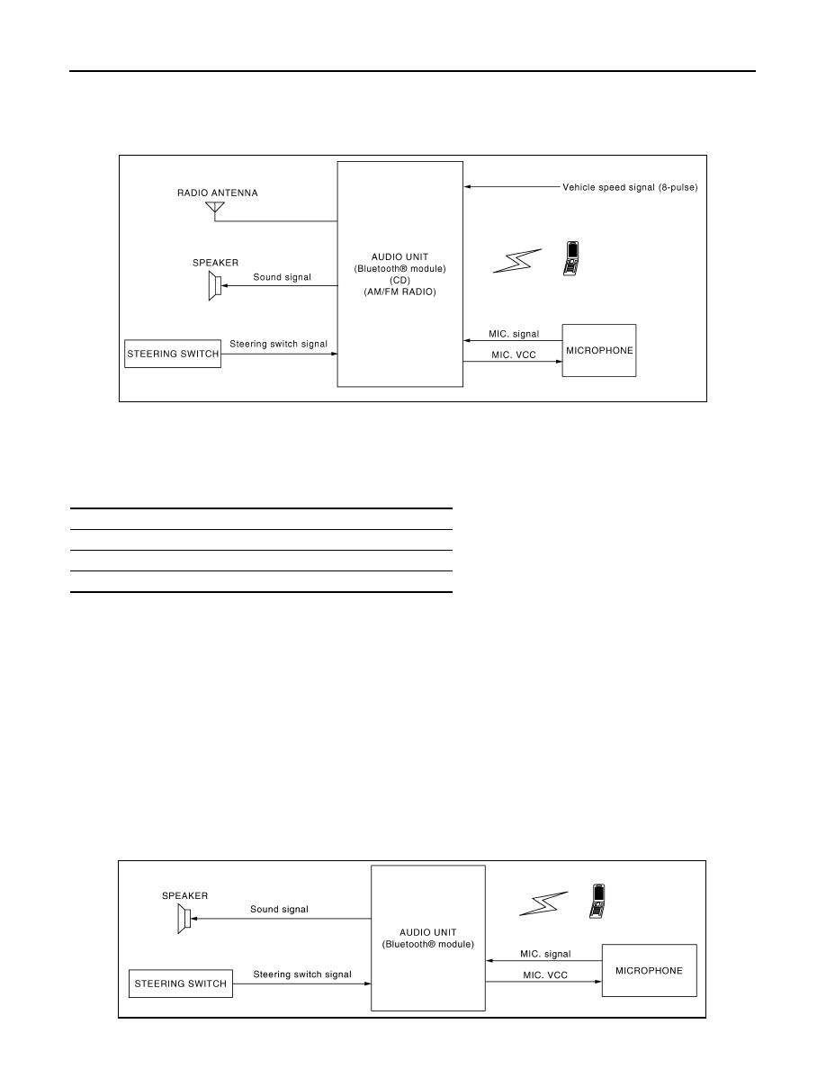
System Diagram

INFOID:0000000000996244

System Description

INFOID:0000000000996245

The audio system is equipped with following function. Each function is operated with audio switch or steering
switch. 

FUNCTION DESCRIPTION

Operating signal

Audio system operation can be performed with audio switch or steering switch.

AM/FM Radio Mode

• AM/FM radio tuner is built into audio unit.
• Audio signal is received by antenna, next it is input to audio unit. Audio unit outputs the audio signal to each

speaker.

CD Mode

• CD function is built into audio unit.
• Audio unit outputs audio signal to each speaker when CD is inserted to audio unit.

Hands-free phone system

• Hands-free communication can be operated by connecting using Bluetooth

®

 with cellular phone.

• Operation is performed by steering switch.
• Guide sound that is heard during operation is output from audio unit to front speaker.

JPNIA0162GB

Function

AM/FM radio

CD

HANDS-FREE PHONE

JPNIA0164GB

AV

AUDIO SYSTEM

AV-7

< FUNCTION DIAGNOSIS >

[AUDIO WITHOUT NAVIGATION]

C

D

E

F

G

H

I

J

K

L

M

B

A

O

P

When a call is originated

• Spoken voice sound output from the microphone (Mic. Signal) is input to audio unit. Audio unit outputs to cel-

lular phone with Bluetooth

® 

communication as a TEL voice signal. Voice sound is then heard at the other

party.

When receiving a call

• Voice sound is input to own cellular phone from the other party. TEL voice signal is output to front speaker,

and the signal is input to audio unit by establishing Bluetooth

® 

 communication from cellular phone.

NATS AUDIO LINK

Description

The link with the NATS IMMU implies that the audio unit can basically only be operated if connected to the
matching NATS IMMU to which the audio unit was initially fitted on the production line.
Since radio operation is impossible after the link with the NATS is disrupted, theft of the audio unit is basically
useless since special equipment is required to reset the audio unit.

Initialization Process for Audio Units That Are Linked to the NATS IMMU

New audio units will be delivered to the factories in the “NEW” state, i.e. ready to be linked with the vehicle's
NATS. When the audio unit in “NEW” state is first switched on at the factory, it will start up communication with
the vehicle's immobilizer control unit (IMMU) and send a code (the “Audio Unit Code”) to the IMMU. The IMMU
will then store this code, which is unique to each audio unit, in its (permanent) memory.
Upon receipt of the code by the IMMU, the NATS will confirm correct receipt of the audio unit code to the audio
unit. Hereafter, the audio unit will operate as normal.
During the initialization process, “NEW” is displayed on the audio unit display. Normally though, communica-
tion between audio unit and IMMU takes such a short time (300 ms) that the audio unit seems to switch on
directly without showing “NEW” on its display.

Normal Operation

Each time the audio unit is switched on afterwards, the audio unit code will be verified between the audio unit
and the NATS before the audio unit becomes operational. During the code verification process, “WAIT” is
shown on the audio unit display. Again, the communication takes such a short time (300 ms) that the audio
unit seems to switch on directly without showing “WAIT” on its display.

When The Radio Is Locked

In case of the audio unit being linked with the vehicle's NATS (immobilizer system), disconnection of the link
between the audio unit and the IMMU will cause the audio unit to switch into the lock (“SECURE”) mode in
which the audio unit is fully inoperative. Hence, repair of the audio unit is basically impossible, unless the
audio unit is reset to the “NEW” state for which special decoding equipment is required.
Clarion has provided their authorized service representatives with so called “decoder boxes” which can bring
the audio unit back to the “NEW” state, enabling the audio unit to be switched on after which repair can be per-
formed. Subsequently, when the repaired audio unit is delivered to the final user again, it will be in the “NEW”
state to enable re-linking the audio unit to the vehicle's immobilizer system. As a result of the above, repair of
the audio unit can only be done by an authorized Clarion representative (when the owner of the vehicle
requests repair and can show personal identification).

Service Procedure

Item

Service procedure

Description

Battery disconnection

No additional action required.

Radio needs repair

Repair needs to be done by authorized rep-
resentative of radio manufacturer since ra-
dio cannot be operated unless it is reset to 
NEW state, using special decoding equip-
ment.

Replacement of radio by new part

No additional action required.

Radio is delivered in “NEW” state.

Transferring radio to another vehicle/re-
placement of radio by an old  part

Radio needs to be reset to NEW state by 
authorized representative of radio manu-
facturer.

Replacement of IMMU

Radio needs to be reset to NEW state by 
authorized representative of Clarion.

After switching on the radio, it will display 
“SECURE” after 1 minute.

AV-8

< FUNCTION DIAGNOSIS >

[AUDIO WITHOUT NAVIGATION]

AUDIO SYSTEM

Component Parts Location

INFOID:0000000000996248

Component Description

INFOID:0000000000996249

No communication from IMMU to radio

1.

Check NATS system if NATS is mal-
functioning.

2.

Reset radio to “NEW” state by autho-
rized representative of Clarion after 
NATS is repaired.

The radio will display “SECURE” after 1 
minute after switching on the radio. Further 
use of radio is impossible until communica-
tion is established again, or after radio is re-
set by authorized representative of Clarion.

When initialized between ECM and IMMU.

Radio needs to be reset to “NEW” status by 
authorized representative of Clarion.

It will display “SECURE” after 1 minute after 
switching on the radio.

Item

Service procedure

Description

1.

Tweeter RH

2.

Tweeter LH

3.

Front door speaker LH

4.

Rear door speaker LH

5.

Radio antenna

6.

Rear door speaker RH

7.

Front door speaker RH

8.

Microphone

9.

Steering switch

10. Audio unit

JPNIA0220ZZ

Part name

Description

AUDIO UNIT

• Operational switch of audio system is integrated.
• Receiving function of AM/FM radio, replaying function of CD and hands-free 

phone function are integrated.

• Audio signals are output to each speaker.

FRONT DOOR SPEAKER

• Outputs sound signal from audio unit.
• Outputs high, mid and low range sounds.

REAR DOOR SPEAKER

• Outputs sound signal from audio unit.
• Outputs high, mid and low range sounds.

TWEETER

• Outputs sound signal from audio unit.
• Outputs high range sound.

STEERING SWITCH

• Operations for audio and hands-free phone are possible.
• Steering switch signal (operation signal) is output to audio unit.

MICROPHONE

• Used for hands-free phone operation.
• Mic. signal is sent to audio unit.
• Power (Mic. VCC) is supplied from audio unit.

RADIO ANTENNA

Radio signal received by antenna is sent to audio unit.

AV

POWER SUPPLY AND GROUND CIRCUIT

AV-9

< COMPONENT DIAGNOSIS >

[AUDIO WITHOUT NAVIGATION]

C

D

E

F

G

H

I

J

K

L

M

B

A

O

P

COMPONENT DIAGNOSIS

POWER SUPPLY AND GROUND CIRCUIT

AUDIO UNIT

AUDIO UNIT : Diagnosis Procedure

INFOID:0000000000996400

1.

CHECK FUSE

Check for blown fuses.

Is inspection result OK?

YES

>> GO TO 2.

NO

>> Be sure to eliminate cause of malfunction before installing new fuse.

2.

CHECK POWER SUPPLY CIRCUIT

Check voltage between audio unit harness connector and ground.

Is inspection result OK?

YES

>> GO TO 3.

NO

>> Check harness between audio unit and fuse.

3.

CHECK GROUND CIRCUIT

1.

Turn ignition switch OFF.

2.

Disconnect audio unit connector.

3.

Check continuity between audio unit harness connector and ground.

Is inspection result OK?

YES

>> INSPECTION END

NO

>> Repair harness or connector.

Power source

Fuse No.

Battery

38

Ignition switch ACC or ON

5

Signal name

Connector No.

Terminal No.

Ignition switch position

Value (Approx.)

Battery power supply

M46

19

OFF

12 V

ACC power supply

M46

7

ACC

12 V

Signal name

Connector No.

Terminal No.

Ignition switch position

Continuity 

Ground

M48

31

OFF

Continuity should exist.


Content   ..  1935  1936  1937  1938   ..