Nissan Qashqai (2007-2010). Manual - part 1938


  Index      Nissan     Nissan Qashqai - service and repair manual 2007 - 2010 year


Search            copyright infringement  


Content   ..  1936  1937  1938  1939   ..


Nissan Qashqai (2007-2010). Manual - part 1938


AV-10

< COMPONENT DIAGNOSIS >

[AUDIO WITHOUT NAVIGATION]

MICROPHONE SIGNAL CIRCUIT

MICROPHONE SIGNAL CIRCUIT

Description

INFOID:0000000000996424

Supply power from audio unit to microphone. The microphone transmits the sound voice to the audio unit.

Diagnosis Procedure

INFOID:0000000000996425

1.

CHECK CONTINUITY BETWEEN AUDIO UNIT AND MICROPHONE CIRCUIT

1.

Turn ignition switch OFF.

2.

Disconnect audio unit connector and microphone connector.

3.

Check continuity between audio unit harness connector terminals 35, 36, 37 and microphone harness
connector terminals 1, 2, 4.

4.

Check continuity between audio unit harness connector terminals 35, 37 and ground.

Is inspection result OK?

YES

>> GO TO 2.

NO

>> Repair harness or connector.

2.

CHECK VOLTAGE MICROPHONE VCC 

1.

Connect audio unit connector.

2.

Turn ignition switch ON.

3.

Check voltage between audio unit harness connector terminal 37 and ground.

Is inspection result OK?

YES

>> GO TO 3.

NO

>> Replace audio unit.

3.

CHECK MICROPHONE SIGNAL 

1.

Connect microphone connector.

2.

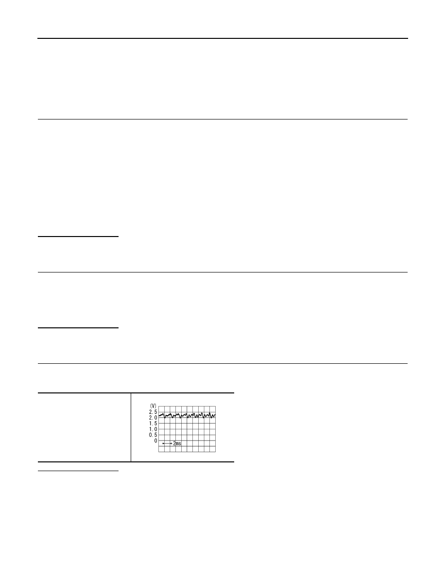
Check signal between audio unit harness connector terminals 35 and 36.

Is inspection result OK?

YES

>> Replace audio unit.

NO

>> Replace microphone.

35 - 1

: Continuity should exist.

36 - 2

: Continuity should exist.

37 - 4

: Continuity should exist.

35, 37 - Ground

: Continuity should not exist.

37 - ground

: Approx. 5 V

35 - 36

PKIB5037J

AV

STEERING SWITCH SIGNAL A CIRCUIT

AV-11

< COMPONENT DIAGNOSIS >

[AUDIO WITHOUT NAVIGATION]

C

D

E

F

G

H

I

J

K

L

M

B

A

O

P

STEERING SWITCH SIGNAL A CIRCUIT

Description

INFOID:0000000000996436

Transmits the steering switch signal to audio unit.

Diagnosis Procedure

INFOID:0000000000996437

1.

CHECK STEERING SWITCH SIGNAL A CIRCUIT

1.

Disconnect audio unit connector and spiral cable connector. 

2.

Check continuity between audio unit harness connector terminal 6 and spiral cable harness connector ter-
minal 24.

3.

Check continuity between audio unit harness connector terminal 6 and ground.

Is inspection result OK?

YES

>> GO TO 2.

NO

>> Repair harness or connector.

2.

CHECK SPIRAL CABLE

Check spiral cable.

Is inspection result OK?

YES

>> GO TO 3.

NO

>> Replace spiral cable.

3.

CHECK AUDIO UNIT VOLTAGE

1.

Connect audio unit connector and spiral cable connector.

2.

Turn ignition switch ON.

3.

Check voltage between audio unit harness connector terminals 6 and 15.

Is inspection result OK?

YES

>> GO TO 4.

NO

>> Replace audio unit.

4.

CHECK STEERING SWITCH

1.

Turn ignition switch OFF.

2.

Check steering switch. Refer to 

AV-11, "Component Inspection"

.

Is inspection result OK?

YES

>> INSPECTION END

NO

>> Replace steering switch.

Component Inspection

INFOID:0000000000996438

Measure the resistance between the steering switch connector terminals 20 to 17 and 16 to 17.

6 - 24

: Continuity should exist.

6 - Ground

: Continuity should not exist.

6 - 15

: Approx. 5 V

AV-12

< COMPONENT DIAGNOSIS >

[AUDIO WITHOUT NAVIGATION]

STEERING SWITCH SIGNAL A CIRCUIT

Standard

Between terminals 20 and 17

VOL UP switch ON

: 634 – 665 

SEEK UP switch ON

: 162 – 168 

SOURCE switch ON

: 0 

Between terminals 16 and 17

VOL DOWN switch ON

: 634 – 665 

SEEK DOWN switch ON

: 162 – 168 

 switch ON

: 0 

JPNIA0167GB

AV

STEERING SWITCH SIGNAL B CIRCUIT

AV-13

< COMPONENT DIAGNOSIS >

[AUDIO WITHOUT NAVIGATION]

C

D

E

F

G

H

I

J

K

L

M

B

A

O

P

STEERING SWITCH SIGNAL B CIRCUIT

Description

INFOID:0000000000999575

Transmits the steering switch signal to audio unit.

Diagnosis Procedure

INFOID:0000000000996441

1.

CHECK STEERING SWITCH SIGNAL B CIRCUIT

1.

Disconnect audio unit connector and spiral cable connector. 

2.

Check continuity between audio unit harness connector terminal 16 and spiral cable harness connector
terminals 32.

3.

Check continuity between audio unit harness connector terminal 16 and ground.

Is inspection result OK?

YES

>> GO TO 2.

NO

>> Repair harness or connector.

2.

CHECK SPIRAL CABLE

Check spiral cable. 

Is inspection result OK?

YES

>> GO TO 3.

NO

>> Replace spiral cable.

3.

CHECK AUDIO UNIT VOLTAGE

1.

Connect audio unit connector and spiral cable connector.

2.

Turn ignition switch ON.

3.

Check voltage between audio unit harness connector terminals 16 and 15.

Is inspection result OK?

YES

>> GO TO 4.

NO

>> Replace audio unit.

4.

CHECK STEERING SWITCH

1.

Turn ignition switch OFF.

2.

Check steering switch. Refer to 

AV-13, "Component Inspection"

.

Is inspection result OK?

YES

>> INSPECTION END

NO

>> Replace steering switch.

Component Inspection

INFOID:0000000000999577

Measure the resistance between the steering switch connector terminals 20 to 17 and 16 to 17.

16 - 32

: Continuity should exist.

16 - Ground

: Continuity should not exist.

16 - 15

: Approx. 5 V


Content   ..  1936  1937  1938  1939   ..