Nissan Qashqai (2007-2010). Manual - part 1901


  Index      Nissan     Nissan Qashqai - service and repair manual 2007 - 2010 year


Search            copyright infringement  


Content   ..  1899  1900  1901  1902   ..


Nissan Qashqai (2007-2010). Manual - part 1901
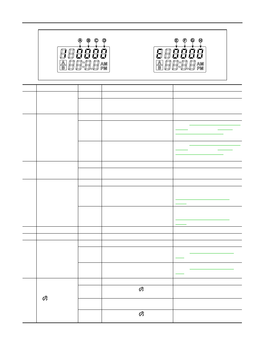


MWI-22

< FUNCTION DIAGNOSIS >

DIAGNOSIS SYSTEM (METER)

ERROR CODE

JSNIA0305ZZ

Items

Code

Description

Action/Reference

(A)

Engine coolant
temperature gauge

0

No malfunction detected

1

If the engine coolant temperature signal 
cannot be received from ECM for 2 sec-
onds or more

Perform ECM self-diagnosis.

(B)

Fuel gauge

0

No malfunction detected

1

If it is judged that the fuel level sensor unit 
signal circuit is short-circuited for 120 sec-
onds or more

Refer to 

MWI-30, "2WD : Diagnosis Pro-

cedure"

 (2WD models) or 

MWI-32, 

"4WD : Diagnosis Procedure"

 (4WD 

models).

2

If it is judged that the fuel level sensor unit 
signal circuit is open-circuited for 120 sec-
onds or more

Refer to 

MWI-30, "2WD : Diagnosis Pro-

cedure"

 (2WD models) or 

MWI-32, 

"4WD : Diagnosis Procedure"

 (4WD 

models).

(C)

Tachometer

0

No malfunction detected

1

If the engine speed signal cannot be re-
ceived from ECM for 2 seconds or more

Perform ECM self-diagnosis.

(D)

Speedometer

0

No malfunction detected

1

If the vehicle speed signal cannot be re-
ceived from the ABS actuator and electric 
unit (control unit) for 2 seconds or more

Perform ABS actuator and electric unit 
(control unit) self-diagnosis. Refer to 

BRC-17, "CONSULT-III Function 
(ABS)"

.

2

If the abnormal vehicle speed signal is in-
put from ABS actuator and electric unit 
(control unit) for 2 seconds or more

Perform ABS actuator and electric unit 
(control unit) self-diagnosis. Refer to 

BRC-17, "CONSULT-III Function 
(ABS)"

.

(E)

0

“0” is always displayed

(F)

0

“0” is always displayed

(G)

Ambient air
temperature

0

No malfunction detected

1

If it is judged that the OAT sensor signal 
circuit is short-circuited for 4 seconds or 
more

Refer to 

HAC-77, "Diagnosis Proce-

dure"

.

2

If it is judged that the OAT sensor signal 
circuit is open-circuited for 4 seconds or 
more

Refer to 

HAC-77, "Diagnosis Proce-

dure"

.

(H)

 switch

• Trip switch

0

No malfunction detected

1

If it is judged that the 

 switch signal cir-

cuit is short-circuited for 5 minutes or more

Replace the combination meter.

2

If it is judged that the trip switch signal cir-
cuit is short-circuited for 5 minutes or more

Replace the combination meter.

3

If it is judged that the 

 switch and trip 

switch signal circuits are short-circuited

Replace the combination meter.

MWI

DIAGNOSIS SYSTEM (METER)

MWI-23

< FUNCTION DIAGNOSIS >

C

D

E

F

G

H

I

J

K

L

M

B

A

O

P

CONSULT-III Function (METER/M&A)

INFOID:0000000000892286

CONSULT-III FUNCTION (METER/M&A)

SELF DIAG RESULT

Refer to 

MWI-51, "DTC Index"

.

DATA MONITOR

Display Item List

X: Applicable

System

Diagnosis mode

Description

METER/M&A

Self Diagnostic Result

Combination meter checks the conditions and displays memorized error.

Data Monitor

Displays combination meter input/output data in real time.

Display item [Unit]

MAIN

SIGNALS

Description

SPEED METER
[km/h]

X

Value of vehicle speed signal received from ABS actuator and electric unit (con-
trol unit) with CAN communication line.
NOTE:
655.35 is displayed when the malfunction signal is received.

SPEED OUTPUT
[km/h]

X

Vehicle speed signal value transmitted to other units with CAN communication 
line.
NOTE:
655.35 is displayed when the malfunction signal is received.

TACHO METER
[rpm]

X

Value of the engine speed signal received from ECM with CAN communication 
line.
NOTE:
8191.875 is displayed when the malfunction signal is received.

W TEMP METER
[

°

C]

X

Value of engine coolant temperature signal received from ECM with CAN com-
munication line. 
NOTE:
215 is displayed when the malfunction signal is input.

FUEL METER
[lit.]

X

Fuel level indicated on combination meter.

DISTANCE
[km]

X

Value of possible driving distance calculated by combination meter.

FUEL W/L
[On/Off]

X

Low-fuel warning status judged by the identified fuel level.

MIL
[On/Off]

Status of malfunction indicator lamp judged from malfunctioning indicator lamp 
signal received from ECM with CAN communication line.

SEAT BELT W/L
[On/Off]

Status of front seat belt buckle switch (driver side).

BUZZER
[On/Off]

X

Buzzer status (in the combination meter) judged with the buzzer output signal re-
ceived from BCM via CAN communication and the warning output condition of 
the combination meter.

C -ENG2 W/L
[On/Off]

Status of malfunction indicator lamp 2 judged from malfunctioning indicator lamp 
signal received from ECM with CAN communication line.

GLOW IND
[On/Off]

Glow indicator lamp status judged from glow indicator lamp signal received from 
ECM with the CAN communication line.

DOOR W/L
[On/Off]

Status of door warning judged from door switch signal received from BCM with 
CAN communication line.

HI -BEAM IND
[On/Off]

Status of high beam indicator lamp judged from high beam request signal re-
ceived from BCM with CAN communication line.

TURN IND
[On/Off]

Status of turn indicator lamp judged from turn indicator signal received from BCM 
with CAN communication line.

MWI-24

< FUNCTION DIAGNOSIS >

DIAGNOSIS SYSTEM (METER)

FR FOG IND
[On/Off]

Status of front fog light indicator lamp judged from front fog light request signal 
received from BCM with CAN communication line.

RR FOG IND
[On/Off]

Status of rear fog light indicator lamp judged from rear fog light request signal re-
ceived from BCM with CAN communication line.

OIL W/L
[On/Off]

Status of oil pressure warning lamp judged from oil pressure switch signal re-
ceived from IPDM E/R with CAN communication line.

LIGHT IND
[On/Off]

Status of light indicator lamp judged from position light request signal received 
from BCM with CAN communication line.

DPF W/L
[On/Off]

DPF warning lamp status judged by the DPF warning lamp signal received from 
ECM with the CAN communication line.

VDC/TCS IND
[On/Off]

Status of VDC indicator lamp judged from VDC OFF indicator lamp signal re-
ceived from ABS actuator and electric unit (control unit) with CAN communication 
line.

ABS W/L
[On/Off]

Status of ABS warning lamp judged from ABS warning lamp signal received from 
ABS actuator and electric unit (control unit) with CAN communication line.

SLIP IND
[On/Off]

Status of slip indicator lamp judged from slip indicator lamp signal received from 
ABS actuator and electric unit (control unit) with CAN communication line.

BRAKE W/L
[On/Off]

Status of brake warning lamp judged from brake warning lamp signal received 
from ABS actuator and electric unit (control unit) with CAN communication line.
NOTE:
Displays “Off” if the brake warning lamp is illuminated when the valve check 
starts, the parking brake switch is turned ON or the brake fluid level switch is 
turned ON.

OIL LEVEL IND
[LEVEL1, 2, 3, 4, 5/CR NG/On]

Oil level status judged by the oil level sensor signal from the oil level sensor.

KEY G W/L
[On/Off]

Status of key warning lamp (G) judged from key warning signal received from 
BCM with CAN communication line.

KEY R W/L
[On/Off]

Status of key warning lamp (R) judged from key warning signal received from 
BCM with CAN communication line.

KEY KNOB W/L
[On/Off]

Key knob switch status received from Intelligent Key unit with the CAN commu-
nication line.

M RANGE SW
[On/Off]

X

Status of mode select switch (manual).

NM RANGE SW
[On/Off]

X

Status of mode select switch (auto).

AT SFT UP SW
[On/Off]

X

Status of position select switch (up).

AT SFT DWN SW
[On/Off]

X

Status of position select switch (down).

P RANGE IND
[On/Off]

X

Status of shift position indicator judged from shift position signal and manual 
mode indicator signal received from TCM with CAN communication line.

R RANGE IND
[On/Off]

X

N RANGE IND
[On/Off]

X

D RANGE IND
[On/Off]

X

4 RANGE IND
[On/Off]

X

3 RANGE IND
[On/Off]

X

2 RANGE IND
[On/Off]

X

Display item [Unit]

MAIN

SIGNALS

Description

MWI

DIAGNOSIS SYSTEM (METER)

MWI-25

< FUNCTION DIAGNOSIS >

C

D

E

F

G

H

I

J

K

L

M

B

A

O

P

NOTE:

Some items are not available according to vehicle specification.

AT CHECK W/L
[On/Off]

A/T check warning lamp status judged by the A/T CHECK indicator lamp signal 
received from TCM with the CAN communication line.

CVT IND
[On/Off]

CVT indicator lamp status judged from CVT CHECK indicator lamp signal re-
ceived from TMC with the CAN communication line.

CRUISE IND
[On/Off]

Status of CRUISE indicator judged from ASCD CRUISE lamp signal received 
from ECM with CAN communication line.

SET IND
[On/Off]

Status of set indicator judged from ASCD SET indicator signal received from 
ECM with CAN communication line.

4WD LOCK SW
[On/Off]

4WD lock switch status judged by the 4WD signal received from 4WD control unit 
with the CAN communication line.

4WD LOCK IND
[On/Off]

4WD lock indicator status judged by the 4WD signal received from 4WD control 
unit with the CAN communication line.

4WD W/L
[On/Off]

Status of 4WD warning lamp judged from 4WD warning lamp signal received 
from 4WD control unit with CAN communication line.

Display item [Unit]

MAIN

SIGNALS

Description


Content   ..  1899  1900  1901  1902   ..