Nissan Qashqai (2007-2010). Manual - part 1899


  Index      Nissan     Nissan Qashqai - service and repair manual 2007 - 2010 year


Search            copyright infringement  


Content   ..  1897  1898  1899  1900   ..


Nissan Qashqai (2007-2010). Manual - part 1899


MWI-14

< FUNCTION DIAGNOSIS >

METER SYSTEM

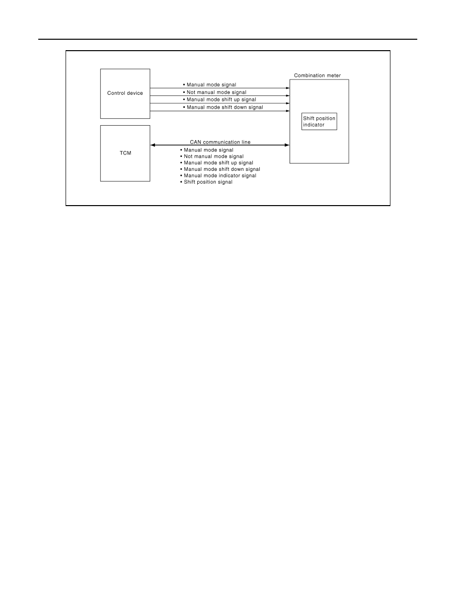
SHIFT POSITION INDICATOR : System Diagram

INFOID:0000000000892268

SHIFT POSITION INDICATOR : System Description

INFOID:0000000000892269

Shift position is displayed in the information display LCD in the combination meter.

MANUAL MODE

• The combination meter receives the manual mode signal, manual mode shift up signal, and manual mode

shift down signal from control device and transmits them to TCM via CAN communication. 

• TCM recognizes the manual mode operation status according to the manual mode signal, manual mode

shift up signal, and manual mode shift down signal received via CAN communication and transmits the man-
ual mode indicator signal to the combination meter via CAN communication. 

• The combination meter indicates CVT position according to the manual mode indicator signal received via

CAN communication. 

NOT MANUAL MODE (AUTO MODE)

• TCM transmits the shift position signal to the combination meter via CAN communication. 
• The combination meter indicates CVT position according to the shift position signal received via CAN com-

munication. 

JSNIA0294GB

MWI

METER SYSTEM

MWI-15

< FUNCTION DIAGNOSIS >

C

D

E

F

G

H

I

J

K

L

M

B

A

O

P

SHIFT POSITION INDICATOR : Component Parts Location

INFOID:0000000000897202

SHIFT POSITION INDICATOR : Component Description

INFOID:0000000000892271

WARNING LAMPS/INDICATOR LAMPS

WARNING LAMPS/INDICATOR LAMPS : System Diagram

INFOID:0000000000892272

WARNING LAMPS/INDICATOR LAMPS : System Description

INFOID:0000000000892273

JSNIA0314ZZ

1.

Fuel level sensor unit (main)

2.

OAT sensor

3.

Oil pressure switch

4.

Oil level sensor

5.

IPDM E/R

6.

Fuel level sensor unit (sub)

A.

Lower right side of rear seat

B.

Lower left side of rear seat (4WD 
models)

Unit

Description

Combination meter

Displays the shift position on the information display with shift position signal and manual mode in-
dicator signal received from TCM.

Control device

Transmits the following signals to the combination meter.

• Manual mode signal

• Not manual mode signal

• Manual mode shift up signal

• Manual mode shift down signal

TCM

Transmits the shift position signal and the manual mode indicator signal to the combination meter 
via CAN communication. 

JSNIA0308GB

MWI-16

< FUNCTION DIAGNOSIS >

METER SYSTEM

OIL PRESSURE WARNING LAMP

• IPDM E/R reads the ON/OFF signals from the oil pressure switch and transmits the oil pressure switch sig-

nal to the combination meter via BCM with the CAN communication line. 

• The combination meter turns the oil pressure warning lamp ON/OFF according to the oil pressure switch sig-

nal received via CAN communication. 

WARNING LAMPS/INDICATOR LAMPS : Component Parts Location

INFOID:0000000000897203

WARNING LAMPS/INDICATOR LAMPS : Component Description

INFOID:0000000000892275

METER ILLUMINATION CONTROL

JSNIA0314ZZ

1.

Fuel level sensor unit (main)

2.

OAT sensor

3.

Oil pressure switch

4.

Oil level sensor

5.

IPDM E/R

6.

Fuel level sensor unit (sub)

A.

Lower right side of rear seat

B.

Lower left side of rear seat (4WD 
models)

Unit

Description

Combination meter

Turns the oil pressure warning lamp ON/OFF according to the oil pressure switch signal received 
from BCM by means of communication. 

IPDM E/R

Reads the ON/OFF signals from the oil pressure switch and transmits the oil pressure switch signal 
to the combination meter via BCM with the CAN communication line. 

Oil pressure switch

Refer to 

MWI-36, "Description"

BCM

Transmits the oil pressure switch signal received from IPDM E/R via CAN communication to the 
combination meter via CAN communication. 

MWI

METER SYSTEM

MWI-17

< FUNCTION DIAGNOSIS >

C

D

E

F

G

H

I

J

K

L

M

B

A

O

P

METER ILLUMINATION CONTROL : System Diagram

INFOID:0000000000892276

METER ILLUMINATION CONTROL : System Description

INFOID:0000000000892277

The combination meter controls the meter illumination according to the position light request signal transmitted

from BCM via CAN communication and the signal from 

 switch joined with the combination meter. 

METER ILLUMINATION CONTROL : Component Parts Location

INFOID:0000000000897204

METER ILLUMINATION CONTROL : Component Description

INFOID:0000000000892279

INFORMATION DISPLAY

JSNIA0307GB

JSNIA0314ZZ

1.

Fuel level sensor unit (main)

2.

OAT sensor

3.

Oil pressure switch

4.

Oil level sensor

5.

IPDM E/R

6.

Fuel level sensor unit (sub)

A.

Lower right side of rear seat

B.

Lower left side of rear seat (4WD 
models)

Unit

Description

Combination meter

Controls the meter illumination according to the position light request signal transmitted from BCM 

via CAN communication and the signal from 

 switch integrated with the combination meter. 

BCM

Transmits the position light request signal to the combination meter via CAN communication. 


Content   ..  1897  1898  1899  1900   ..