Content .. 1898 1899 1900 1901 ..
Nissan Qashqai (2007-2010). Manual - part 1900
MWI-18
< FUNCTION DIAGNOSIS >
METER SYSTEM
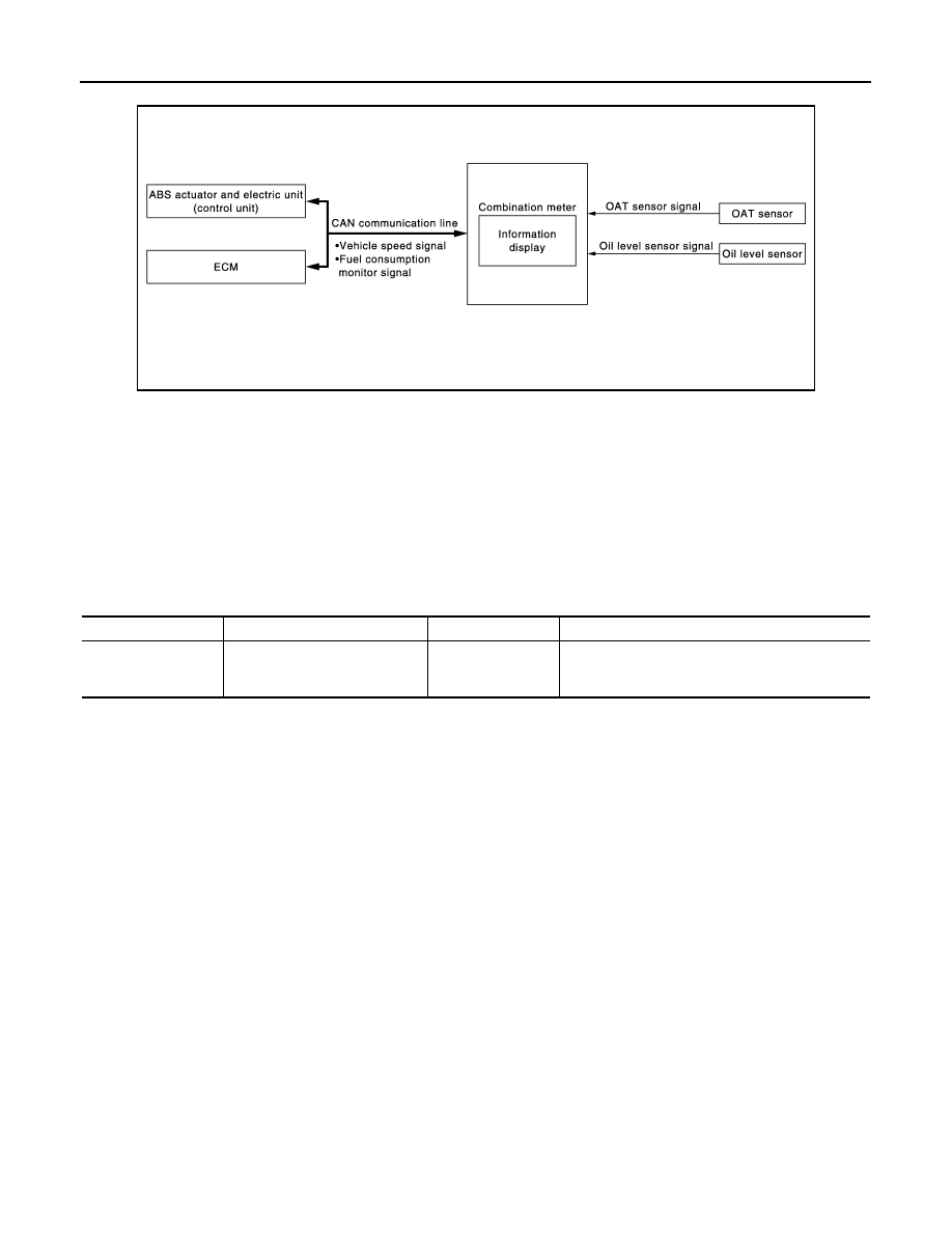
INFORMATION DISPLAY : System Diagram
INFOID:0000000000892280
INFORMATION DISPLAY : System Description
INFOID:0000000000892281
DESCRIPTION
• The combination meter retrieves the information required for controlling the operations of the information
display from BCM with the CAN communication lines.
• The combination meter incorporates a trip computer that displays the information according to the signal
received from various units.
MAINTENANCE
The remaining distance from the set maintenance distance is displayed.
OIL LEVEL
The combination meter displays it judged with the oil level signal received from the oil level sensor.
CLOCK
Clock displays the time measured in the combination meter.
AVERAGE FUEL CONSUMPTION
Control Outline
• The combination meter receives the fuel consumption monitor signal from ECM and the vehicle speed signal
from the ABS actuator and electric unit (control unit) via CAN communication.
• The combination meter indicates the average fuel consumption calculated by the signal received.
• The average fuel consumption displayed on the information display is uploaded at approximately 30-second
intervals.
AVERAGE VEHICLE SPEED
• The combination meter receives the vehicle speed signal from the ABS actuator and electric unit (control
unit) with the CAN communication line.
• The combination meter indicates the average vehicle speed according to the vehicle speed signal received
and the time measured in the combination meter.
• The average vehicle speed displayed on the information display is uploaded at approximately 30-second
intervals.
TRAVEL TIME
Control Outline
Measures the driving time (ignition switch ON time) in the combination meter and displays it.
ODO/TRIP METER
JSNIA0295GB
Items
Setting range
Setting unit
Description
Maintenance
0– 63000 km
(0 – 31500 miles)
1000 km
(500 miles)
The remaining distance from the set distance is dis-
played for 5 seconds after the ignition switch is
turned ON.