Nissan Qashqai (2007-2010). Manual - part 1897


  Index      Nissan     Nissan Qashqai - service and repair manual 2007 - 2010 year


Search            copyright infringement  


Content   ..  1895  1896  1897  1898   ..


Nissan Qashqai (2007-2010). Manual - part 1897


MWI-6

< FUNCTION DIAGNOSIS >

METER SYSTEM

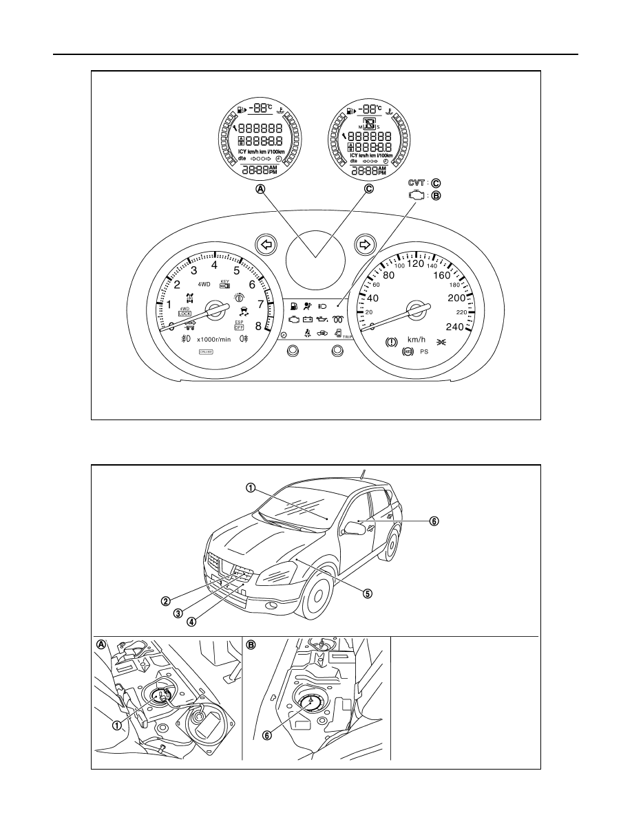
ARRANGEMENT OF COMBINATION METER 

METER SYSTEM : Component Parts Location

INFOID:0000000000892246

JSNIA0321ZZ

A.

M/T models

B.

Diesel engine models

C.

CVT models

JSNIA0314ZZ

MWI

METER SYSTEM

MWI-7

< FUNCTION DIAGNOSIS >

C

D

E

F

G

H

I

J

K

L

M

B

A

O

P

METER SYSTEM : Component Description

INFOID:0000000000892247

METER SYSTEM : Operation Description

INFOID:0000000000903726

TRIP COMPUTER

• The display switches in the following order when pressing the trip

switch (1) of the combination meter. 

- Trip  A 

 Trip B 

 Possible driving distance 

 Average fuel con-

sumption 

 Average vehicle speed 

 Travel time 

 Trip A.

• The items other than “odo meter” and “possible driving distance”

can be reset when pressing and holding the trip switch for 1 sec-
ond or more. 

• All items other than “odo meter” and “possible driving distance” can

be reset when pressing and holding the trip switch for 3 seconds or
more. 

MAINTENANCE

1.

Turn ignition switch ON from OFF.

1.

Fuel level sensor unit (main)

2.

OAT sensor

3.

Oil pressure switch

4.

Oil level sensor

5.

IPDM E/R

6.

Fuel level sensor unit (sub)

A.

Lower right side of rear seat

B.

Lower left side of rear seat (4WD 
models)

Unit

Description

Combination meter

Controls the following with the signals received from each unit via CAN communication and the sig-
nals from switches and sensors. 

• Speedometer

• Tachometer

• Warning lamps

• Indicator lamps

• Information display

• Warning chime

IPDM E/R

Reads the ON/OFF signals of the oil pressure switch and transmits the oil pressure switch signal to 
the combination meter via BCM with CAN communication line.

Fuel level sensor unit

Refer to 

MWI-30, "2WD : Description"

 (2WD) or 

MWI-31, "4WD : Description"

 (4WD).

Oil pressure switch

Refer to 

MWI-36, "Description"

.

ECM

Transmits the following signals to the combination meter with CAN communication line.

• Engine speed signal

• Engine coolant temperature signal

• Fuel consumption monitor signal

ABS actuator and electric unit
(control unit)

Transmits the vehicle speed signal to the combination meter with CAN communication line.

BCM

Transmits signals provided by various units to the combination meter with CAN communication line.

Control device

Transmits the following signals to the combination meter.

• Manual mode signal

• Not manual mode signal

• Manual mode shift up signal

• Manual mode shift down signal

TCM

Transmits shift position signal to the combination meter.

Brake fluid level switch

Transmits the brake fluid level switch signal to the combination meter.

Parking brake switch

Refer to 

WCS-23, "Description"

.

JSNIA0306ZZ

MWI-8

< FUNCTION DIAGNOSIS >

METER SYSTEM

2.

Press and hold the trip switch (1) for 3 seconds or more while
displaying the maintenance information to the information dis-
play (for approximately 5 seconds after the ignition switch is
turned ON). 

3.

The maintenance information is flashed and the system enters
in the set/reset mode. 

4.

The set/reset can be performed with the following operation dur-
ing flashing. 

CLOCK

• The display switches between 12-hour time display mode and 24-

hour time display mode with pressing the 

 switch (1) of the com-

bination meter. 

• The “hour” display of clock is flashed when pressing and holding

the 

 switch for 3 seconds or more, and then the clock switches to

the time adjustment mode. 

METER ILLUMINATION CONTROL

Nighttime Mode

The meter illumination is adjusted to 22 steps by turning the 
switch (1). (Daytime mode cannot be adjusted.)

SPEEDOMETER

SPEEDOMETER : System Diagram

INFOID:0000000000892248

SPEEDOMETER : System Description

INFOID:0000000000892249

Trip switch

Pressed

: Reset

Turn right

: Increase the set distance

Turn left

: Decrease the set distance

JSNIA0306ZZ

 switch

Pressed

: Changing adjustment “hour” and “minute”

Turn right

: Go

Turn left

: Back

JSNIA0304ZZ

 switch

Turn right

: Lightening

Turn left

: Darkening

JSNIA0304ZZ

JSNIA0289GB

MWI

METER SYSTEM

MWI-9

< FUNCTION DIAGNOSIS >

C

D

E

F

G

H

I

J

K

L

M

B

A

O

P

• The ABS actuator and electric unit (control unit) converts the rectangular wave signal provided by the wheel

sensor to a vehicle speed signal and transmits it to the combination meter via CAN communication. 

• The combination meter indicates the vehicle speed to the speedometer according to the vehicle speed sig-

nal received via CAN communication. 

SPEEDOMETER : Component Parts Location

INFOID:0000000000897197

SPEEDOMETER : Component Description

INFOID:0000000000892251

TACHOMETER

TACHOMETER : System Diagram

INFOID:0000000000892252

TACHOMETER : System Description

INFOID:0000000000892253

JSNIA0314ZZ

1.

Fuel level sensor unit (main)

2.

OAT sensor

3.

Oil pressure switch

4.

Oil level sensor

5.

IPDM E/R

6.

Fuel level sensor unit (sub)

A.

Lower right side of rear seat

B.

Lower left side of rear seat (4WD 
models)

Unit

Description

Combination meter

Indicates the vehicle speed to the speedometer according to the vehicle speed signal received from 
ABS actuator and electric unit (control unit) via CAN communication.

ABS actuator and electric unit 
(control unit)

Transmits the vehicle speed signal to the combination meter with CAN communication line.

JSNIA0290GB


Content   ..  1895  1896  1897  1898   ..